Announcement

Collapse
No announcement yet.

Rick's Overbalanced Water Wheel Concept

Collapse
X
 
  • Filter
  • Time
  • Show
Clear All
new posts

  • Rick's Overbalanced Water Wheel Concept

    First of all, please note that the first image shown below is not my concept for an overbalance water wheel. It comes from another discussion thread on this forum which I had visited because of my interest in the topic of discussion. I originally began posting ideas for an overbalanced water wheel concept in the Bhaskara's Wheel thread, which had been started in October 2016 as a poll to determine whether or not the claims of an experimenter, who had claimed his wheel would rotate continuously, was real or fake. His build, simply a bicycle wheel with half-filled soda bottles tied to the perimeter, is seen below.


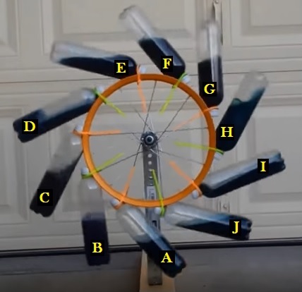
    The experimenter had put up a YouTube video claiming to show the wheel turning non-stop for 5 minutes. It didn't take long to determine that the claims were false, as Peter Lindemann suggested by doing a quick center of gravity analysis. I concurred with Peter's analysis, and after studying the YouTube video there was no doubt whatsoever that the experimenter had posted a hoaxed video. As I mentioned in post #9 of the Bhaskara's Wheel thread, I noticed that there were two recurring chirping sounds (a higher pitched one followed by a lower pitched one 2.5 seconds later. This may have been a bird outside the garage, and it is not all that unusual for a bird to make two differing pitched chirps close together. What I did find unusual, though, was the fact that when I timed the interval starting immediately upon hearing the high pitched chirp, and ending immediately after each successive high pitched chirp, it always timed out at 19.6 seconds during this 5 minute run. This, of course, is pretty much a dead giveaway that the video was edited to loop within that 19.6 second time frame, which could have started at the chirp or anywhere in between chirps.

    Although the video was obviously hoaxed, and there was no way that the above shown water wheel could possibly rotate on its own, there were two things about the build that interested me - the angular placement of the soda bottles, and the sloshing effect of the liquid each time a bottle was inverted. I saw how these two elements could be utilized for true overbalance rotation in a perfected water wheel design, and set about making some drawings to illustrate the concept that came to mind.

    After submitting several concept drawings within the Bhaskara's Wheel thread, I decided it would be best to start a new thread for this concept. Since the wheel initially being discussed in the Bhaskara's Wheel thread was quickly proven to be a hoax, I thought that readers would tend to exit the thread quickly without staying long enough to review what I was explaining further on. Thus, I'll leave one last post in that thread to steer anyone interested in my concept design to this new thread where I will fully share all details about the evolution of this overbalance water wheel.

    I started out with a basic concept, which involved moving all the water on the right side of the wheel inward by utilizing a channel at the wheel's perimeter, dividing that channel into sections using barriers, and attaching a tube to the side of each section by means of a 90 degree elbow fitting. The below drawing shows how that would work each time the tube was inverted during rotation.


    The layout of the wheel itself, for the above configuration, is shown in the next drawing, with the dotted lines representing the baffles that would divide the perimeter into 12 enclosed sections which would feed water out to a tube as rotation brought a tube out over the top of the wheel, and then act as a receiver for water emptying from a tube as the tube lifted above the horizontal plane when rising from the bottom of the wheel.


    I then showed how the wheel would look with the tubes attached and partially filled with water. As you can see, while this is definitely a huge improvement over the soda bottle experiment, there was still much room for further improvement. While the 4 tubes (A, B, C, and D) on the left side of the wheel would definitely provide overbalance to more than 4 perimeter sections on the right side, the question remained as to whether those 4 tubes on the left side were capable of overbalance to the entire water weight found on the right side (2 tubes plus 6 perimeter sections).


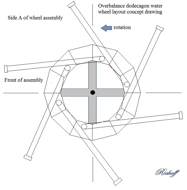
    It appeared evident that, in order to obtain counter-clockwise rotation, I would need to increase the angularity of the tubes so that tube L would lay downward enough to occupy the space shown occupied by tube A. This would allow tube L to be filled at this stage of rotation, while tube F would already have emptied its water back into the perimeter. The only way to achieve those positive changes would of course require having only six tubes on the side of the wheel. I still wanted 12 tubes, and to keep that configuration only required moving six of the tubes to the opposite side of the wheel and attaching them to perimeter sections that would be unoccupied. Thus the 12 tubes would alternate from one side to the other every 30 degrees along the perimeter. This could be done with a one wheel or two wheel build, but I felt that a single wheel build would have the advantage of being more cost efficient. I also determined that, for ease of building such a wheel, I should scrap the idea of constructing water tight perimeter sections in favor of a far simpler solution that would bring water at the right side of the wheel's perimeter even further inward. My idea for the improved concept was to redesign the wheel to be built as a 12 sided polygon, which is called a dodecagon. The next drawing shows the configuration for side A of the wheel.


    Side B of the wheel is similarly constructed, keeping in mind that the tubes are positioned 30 degrees apart from those on side A, along with the fact that the tubes appear reversed because you are observing the reverse side.


    These side A and side B layouts requires longer tubes than shown in the previous drawing, in order to extend a similar amount beyond the perimeter, but at the same time there is twice the amount of tube laying on the face of the dodecagon, and that coverage is mostly centered further inward towards the axle. What this means, of course, is that each tube can act as its own feeder and receiver, and that the tubes only need be connected to the dodecagon section bore holes, while each dodecagon section is simply a flat board. All that remained was to provide a drawing showing the tubes with water fills for both sides of the wheel at once, and to determine the available torque at both sides of the center line so as to show whether or not an overbalance condition could actually be achieved. In my next post I will show such a drawing and explain how I obtained my calculations.


    Best to all,

    Rick
    Last edited by rickoff; 05-02-2018, 02:46 AM.
    "Seek wisdom by keeping an open mind to alternative realities, questioning authority, and searching for truth. Only then, when you see or hear something that has 'the ring of truth' to it, will it be as if a veil has been lifted, and suddenly you will begin to hear and see far more clearly than ever before." - Rickoff

  • #2
    In the drawing seen below, I am showing both sides of the dodecagon wheel populated with tubes. This view would be similar to what you would see if you were looking at clear dodecagon sections and clear tubes. That isn't how I'd suggest building the water wheel, as that would be quite expensive, but it works well for illustrative purposes. As you can see, I have colored the water blue to represent water in tubes on this side of the wheel, while water in tubes on the opposite side is colored green. Overlapping fill areas of the tubes is represented by a bluish-green color. You will also note that each tube has a yellow circle with a black dot in its center, and this represents the center, or mid point, of water weight distribution. These dots are used to obtain relatively precise measurements from the dots to the centerline of the wheel. I did that right on my laptop computer screen, using a millimeter scaled ruler, while viewing the above drawing at one zoom-in level (twice normal size) with Microsoft Paint. Viewing at this larger size allows more accurate distance measurements.


    Those distances can be converted from millimeters to inches for any desired build size, and when all the distances left of the centerline are summed together and compared to the sum of all distances right of the centerline, we can then see if we end up with an overbalance condition. For purposes of examining a build using a 46.5 inch diameter dodecagon, I am basing water fill weights to be 5 pounds for each tube. With both this factor and the distances from the centerline known, it is a simple matter to calculate the available torque, in foot-pounds, for each tube separately, as well as to calculate the full amount of torque available on either side of the centerline. If one side has more torque than the other, the resultant available overbalance torque can then be determined.


    After an exhaustive analysis of the parameters which I mentioned, I was able to determine that there is indeed an overbalance condition at the left side of the centerline. The amount of that overbalance torque is 6.07 foot-pounds, which is about 16 percent greater than the available torque for the right side, and this same 16% overbalance holds true no matter what size pipes are being used for the build. While that is definitely good news, I'm sure that you must be thinking that 6.07 foot-pounds isn't all that exciting. After all, that would be like tying a 3/4 gallon container of milk to a fulcrum placed one foot beyond the wheel's centerline on the horizontal axis. Would that turn the wheel? Yes, of course it would, but would that be enough torque to provide enough useful work to make building this water wheel a worthwhile endeavor?

    I'd say that depends on what you were hoping to be able to do with the wheel. You could certainly use it 24 hours a day to generate what would be a small amount of electrical power each month, but generating enough power to go off grid, or to sell excess power to neighbors or the electric company wouldn't be an option. A worthwhile use, however, might be in recharging batteries used in a solar power system, especially during overcast days or hours of darkness. Another practical use would be to pump water which could be used for irrigation, or stored in an elevated tank for use on demand. And what if we increased the build size proportionally great enough so that we could use 4 inch tubes, 6 inch, 8 inch, or 12 inch tubes, rather than the 3 inch tubes used for this illustrative example? I did in fact calculate the available torque for those build sizes, and the results seemed quite impressive.

    Keep in mind that a build using 4 inch tubes would require the wheel being scaled to 4/3 times the size of the illustrated wheel, while a build for 6 inch tubes would require a wheel twice the size illustrated. The tube lengths would increase in the same proportions, of course. Now perhaps you are thinking that a build using 4 inch tubes, being 1/3 larger than the 3 inch build, would yield only 1/3 again the available overbalance torque, but that's not how this works. You need to remember that you are not only increasing the diameter of the tube, but also increasing the fill height of each tube when building to a larger scale. Here's how the water fill weights compare for each size of build mentioned (3", 4", and 6"):


    As you can see, while the 4" build is only 1.33 times the size of the 3" build, the water weight yield is more than twice as much, and doubling the build size for 6" tubes yields nearly 8 times the water weight! Now keep in mind that with these larger build proportions we are also increasing the distance of the water fill weight centers from the wheel's centerline, and thus in addition to the increase in weight we also gain substantially from the distance times weight calculations, in foot pounds, of available torque for each tube. While we only had 6.07 foot-pounds of available rotational torque from the 3" build, that figure increases to 18.569 foot-pounds for a 4" build, and a whopping 94.727 foot-pounds for a 6" build! Thus, the torque yield for a 4" build is more than 3 times greater than on a 3" build, and more than 15 times greater with a 6" build! Incidentally, doubling the build scale from any size pipe to a larger pipe consistently provides for about a 15.5 times torque increase. In comparison to the 6" build torque specification of 94.727 foot-pounds, a 25 horsepower electric motor develops 75 foot-pounds torque while running at 1750 rpm and consuming a considerable amount of electrical power. A 50 horsepower electric motor running at the same speed would produce 150 foot-pounds torque, or double that of the 25 horsepower motor, but also uses twice as much electric power to operate. The overbalance water wheel consumes nothing, of course. I should mention that this comparison only takes into account the applied force in foot-pounds. Actual work being done would be calculated as applied force times distance traveled, and obviously a motor turning at 1750 rpm would move the applied force much further than a 6" pipe scale water wheel turning at perhaps 6 rpm. I'll show the actual calculations for work being done later in another post.


    I had originally expected that the percentage of overbalance would remain the same for this water wheel concept no matter what size the build is scaled to, and it turns out that this theory holds true. My calculations show that the amount of overbalance condition for any build size is 16 percent, meaning that tubes A, B, C, and D at the left of the water wheel's vertical centerline produce 16% more torque than tubes E through L, which have water weight centers at the right of the wheel's vertical centerline.


    The torque calculations show that building larger is definitely a far better option if you want to utilize the rotational torque for any particular purpose. If you are interested in reviewing my torque calculations, you can view and/or download the pdf document here. I have also developed a water wheel torque calculator that you may download, which quickly calculates the applied torque for all pipe sizes from 3 inch to 12 inch, based upon the scaled drawing measurement, in millimeters, from a tube's water fill weight center to the vertical centerline of the water wheel. And if you would like to download the above drawing directly so as to take your own measurements and verify my computations, you can download the drawing at this link. You are free to use this, or any of my other drawings, as long as you do not edit and/or re-post any drawing to this thread or elsewhere on this or other forums. I do copyright my drawings, and will hold anyone accountable for misuse or abuse of user privileges.

    Depending on the size of your computer screen, your measurements could be somewhat different, but they should be very close to mine in a size relationship. I'd encourage others to do the work to either verify my computations or call attention to any error that may be found. While I was very careful, and triple checked all my results, it certainly is possible that I may have erred or overlooked something. If you can find an error then please report that to me in a private message and I will correct the error and give you credit for finding it once I validate it. By all means, though, please do the math before you jump to any conclusions or post to this thread, thinking that anything I have stated is not factual, as the proof that this concept can work as stated is all in the math and doing the calculations correctly.

    I'll provide further drawings and build specifications in this thread, but I'd suggest for the time being that anyone interested in building this concept wheel should hold off for a while until my observations can be verified by others. It might be a good idea to build a scaled down version first for proving the concept.

    I haven't done any calculations yet for a build using tubes smaller than 3 inches, but could certainly provide that data. I have doubts that anything smaller than a 1" build would even work, as the smaller diameter would tend to impede the flow of water. The larger the diameter of the tubes used, the faster the water transfer takes place. By the way, the diameter of a dodecagon wheel for a 1 inch build would be 1/3 that for the 3 " build, or 15.5 inches, and could be made from a single piece of 1/4 or 3/8 inch plywood or masonite hardboard cut out as a circle. The 3" version can also be made from half of a 4 foot by 8 foot sheet of 3/4 inch plywood, though constructing a dodecagon wheel of that size would be even less expensive. More on that later, though.

    For now, let's just think about what this wheel might possibly be capable of if the concept can work just half as well as it does theoretically. I think that should be quite possible, especially when we haven't even taken into account the additional rotational force that will be made available by the hammering, or sloshing effect, which will occur as water in each tube is in the process of being shifted outward and downward. I'll explain that further in another post, and will offer a drawing showing layout considerations for differing tube sizes.

    Best to all,

    Rick


    Last edited by rickoff; 09-17-2018, 09:07 PM. Reason: Updated information and download links
    "Seek wisdom by keeping an open mind to alternative realities, questioning authority, and searching for truth. Only then, when you see or hear something that has 'the ring of truth' to it, will it be as if a veil has been lifted, and suddenly you will begin to hear and see far more clearly than ever before." - Rickoff

    Comment


    • #3
      An interesting thought has occurred to me Rick. As the wheel speeds up it will reach a speed where the centrifugal force will begin to cause the water to not want to move back to the center. So that will be a self regulating speed control. As the wheel gets loaded and slows down the water will again flow more freely back to the center and increase the torque of the wheel. I am really looking forward to someone building this and trying it out. I just don't have time myself right now to take on a project of this size.

      Great work so far!

      Take care,
      Carroll
      Just because someone disagrees with you does NOT make them your enemy. We can disagree without attacking someone.

      Comment


      • #4
        In response to Carroll

        Thanks for your input, Carroll. In post #21 of the Bhaskara's Wheel thread I mentioned this very effect, saying, "Folks who are interested in this concept should keep in mind that an overbalance water wheel should only be expected to turn slowly. If it were to turn anything but slowly then the centrifugal force would work against the flow of water back towards the perimeter sections, and of course that would negate the effects we are hoping to achieve." You are correct in stating that the wheel would tend to be somewhat self-regulating, in that if it was to speed up to anything but a very slow turn then water would stay in the outermost part of the tubes, thus balancing the wheel. At that point the wheel would slow down until enough water could flow back towards the center of the wheel on the right side of the centerline to bring the state of the wheel back into an overbalance condition where rotational force would resume.

        Just how slowly we should expect the wheel to turn would of course be dependent on the size of the build. Since the perimeter of a larger build would be moving faster than a smaller build at the same rpm, the rpm of the larger wheel would have to be reduced accordingly. Self regulation would probably do the trick, but to avoid any possibility of a wavering speed, or jerky motion, the driven load upon the wheel would best be optimized to maintain the wheel at a desired rpm that constantly falls within the overbalance zone.

        For the 3 inch build on a nearly 4 foot diameter wheel, I'd suspect that the desired rpm might be in the neighborhood of perhaps 10 to 12 rpm, which would be one full revolution in 5 to 6 seconds. For the 6 inch build upon a wheel of close to 8 feet in diameter, the rpm would have to be reduced considerably.

        The circumference of an 8 foot wheel is 25.133 feet, which is twice the circumference of a 4 foot wheel. That indicates that the rpm of the 6 inch build would have to be cut down to 5 or 6 rpm, and of course this is just guesswork - it might be even slower. We have to keep in mind that we're after torque - not speed, and the slower the speed of this wheel, the greater the overbalance torque will be. The perfect speed would be the speed where the wheel is just barely moving, as this would allow fastest transfer of water while operating as close to the theoretical observation as possible.

        In addition to being a self-regulating wheel, this wheel would also be a self-starter, meaning that if the wheel was held in any position, and then released, it would begin rotating simply because an overbalance condition would always exist.

        As I mentioned in my post #2, we haven't even taken into account the additional rotational force that will be created by the hammering, or sloshing effect, of the water as it falls outward and downward to fill a tube. As you can see from the water weight specs that I showed in post #2, there is a substantial water weight falling down the tube (more than 39 pounds with a 6" tube size). When that weight smacks into the bottom of the tube, I'm sure you can realize that there would be quite an impact, and that in itself would probably be enough to advance the wheel to the next position where a tube is about to be filled. On the right side of the centerline you will have tubes sending water back towards the wheel's center, and so there will also be somewhat of a counter-force hammer effect, but because the water is channeled towards the side of the dodecagon sections by the elbows, rather than in a downward trajectory, any such counter-force should be greatly reduced.
        Last edited by rickoff; 09-16-2018, 01:25 PM. Reason: updated for accuracy
        "Seek wisdom by keeping an open mind to alternative realities, questioning authority, and searching for truth. Only then, when you see or hear something that has 'the ring of truth' to it, will it be as if a veil has been lifted, and suddenly you will begin to hear and see far more clearly than ever before." - Rickoff

        Comment


        • #5
          Response to BroMikey

          Originally posted by BroMikey
          So lets say 5 pounds per tube. It looks like to me you will have 15 lbs of available force. If we used 5 gallons per tube that might be 150 lbs available and 55 gallon drum size tubes would 1600 lbs torque.

          There are only 3 tubes pulling down all of the time. Not a bad analysis
          I thought it would be harder than this.
          Sorry, Mikey, but your reasoning is flawed. The actual force is dependent not only upon the applied weight in each tube, but also the distance the center of that weight lies from the wheel's vertical centerline. Multiplying each distance by the weight provides us with the foot-pounds of available force, or torque, for each tube. I'd suggest that you rethink your rapid analysis and take the time to properly calculate the torque in the manner which I described in post #2.

          If you go back and look at the drawing, you will see that, at the stage of rotation depicted, there are 4 tubes (A, B, C, and D) providing rotational force on the left side of the center line. Tube D will continue aiding rotation until its marked center of water fill weight falls directly behind the vertical centerline. At that point it will have zero torque, and then there will be 3 tubes at the left side providing rotational force. Tubes L and F will be level and at the mid-point of transitioning at that same moment, which means that they will have a neutral effect until the next one degrees of rotation, when their water weights will be shifted further left, meaning that L will then become overbalanced to F and will begin aiding the rotational force of tubes A, B, and C. In other words, the wheel will always be in an overbalance condition at the left side of the centerline.
          Last edited by rickoff; 04-05-2018, 11:13 PM.
          "Seek wisdom by keeping an open mind to alternative realities, questioning authority, and searching for truth. Only then, when you see or hear something that has 'the ring of truth' to it, will it be as if a veil has been lifted, and suddenly you will begin to hear and see far more clearly than ever before." - Rickoff

          Comment


          • #6
            Over shot wheel

            A number of years ago I made a small simple over shot wheel .says about 10 inch's across with hinges steel arms that would at the top flop over and keep it running for a while.. Two things came up .one was the wheel excelerated fast then slowed to a stop.but why the exceleration ?.the second was ...I noticed that with more arms better results ..and then a question came to me why only one wheel ??I mean why not 10 wheels on a common shaft each off set a little to over come the weak points ? With more units the stop point would get smaller till you reach a point of extra arms input . just a thought .

            Comment


            • #7
              Response to Jim Glinski

              Without a video, photo, or a scaled drawing of your wheel to examine, all one can do is to speculate. If your wheel came to a stop on its own, as you say, then obviously it would not start on its own. In other words, you had to at least move it to a position where some hinges were already in an open position, others on the opposite side were closed, and one hinge which had just passed over the top in a closed position was ready to flop over. You then nudged the wheel a little further, to cause the hinge to open and flop over, and this caused an impact that set the wheel in motion (briefly accelerating) before coming to a stop. Your nudge was part of the force that went into rotating the wheel, but without subsequent nudges the wheel was doomed to stop. This is a common problem with attempts at mechanical overbalancing where arms are intended to flop over. Here's an example of such an attempt, as illustrated by Norman Rockwell. Interestingly, this was featured on the October 1920 magazine cover. Of course the reason why the metallic ball weights at the right side of the wheel, when flopped over to provide leverage, did not create an overbalance condition is because the sum of the centers of gravity right of the vertical centerline was equal to the sum of the centers of gravity for the steel balls on the left side. The only impetus for rotation, therefore, would be the thrust provided at the moment that a ball flops over and reaches its full extent, thus causing a striking, or hammering effect. Once again, though, as in your own attempt at mechanical overbalancing with hinges, the rotational impetus must begin by initiating rotation by setting the wheel spinning with your hand, and since that hand assistance is not continued the wheel must slow down and stop.

              Last edited by rickoff; 04-06-2018, 02:05 PM.
              "Seek wisdom by keeping an open mind to alternative realities, questioning authority, and searching for truth. Only then, when you see or hear something that has 'the ring of truth' to it, will it be as if a veil has been lifted, and suddenly you will begin to hear and see far more clearly than ever before." - Rickoff

              Comment


              • #8
                Dodecagon bore hole layouts


                I am adding a drawing here, representing the left upper quadrant of the wheel, to show the layout specifications for the boring of holes for builds using 3 inch, 4 inch, and 6 inch tubes. These are the bore holes that accommodate the tube end that is attached to the dodecagon wheel. A short piece of tube extends from the 90 degree elbow, passes through the 3/4 inch thick board comprising one dodecagon section, and the tube is capped off on the other side to both close the tube and retain it. Since it is the outside diameter (O.D.) of the tube that must pass through the bore, each bore hole is drilled to that O.D specification. The 3 inch (3") PVC DWV tubes, for example, have an O.D. of 3.5" and so they require a 3.5" bore hole. The circles shown in the below drawing are larger than the pipe O.D. for each pipe size listed, and there is a reason for that. The circles actually represent the O.D. of the 90 degree elbow that the tube is fitted into. For the 3" tube, that would be 4" at the widest part of the elbow flange. This needs to be taken into account because each tube fixed upon a radian line is rotated downward until it rests against an elbow located on a radian line 60 degrees away from the bore hole radian. It is highly desirable that the tube lay against the elbow of another tube because this both maximizes the tube's angle of attachment to the wheel and also offers the advantage of attaching the tube to the elbow with a strap. Further out towards the wheel's perimeter, it would be wise to provide an offset block to attach and cradle each tube, and at the farthest outer extent each tube could be tied together by cable to provide further stability and to keep the spacing between each tube's end very precise. Such precision and stability is very important for proper dry balancing of the wheel. I'll write more about these attachments, and balancing, later on in the thread.

                As seen in the drawing, there is a line drawn from the inside of the first circle on the y axis to the top O.D. of the elbow shown on the radian line 60 degrees away from the y axis. This line represents how a 3.5" O.D. tube would lay upon the elbow. The drawing shows that the angle of inclination is 68 degrees. It should be noted that if the center of the bore holes were brought closer to the axle's center point then the angle would change to become larger because the tube would rest upon the elbow sooner. For example, if y1 was shortened from 18" to 15" then the angle would be 70 degrees, and if shortened to 12" the angle would be 72 degrees. Each degree larger would mean that water in a tube would be flowing outward later than desired, so it would be important to keep the angle very close to 68 degrees to maintain specifications. Thus, boring the holes at the dimensions shown should be very closely observed.


                Note that all dimensions shown in inches for a 3 inch build relate to what would be true for 3" tubes and 3.5" bore holes. I also give the formulas (at lower right of the drawing) for figuring the dimensions required for the larger builds. In planning for a larger build, one would of course need to know the O.D. dimensions for those tubes in order to bore the holes correctly. A 4" tube has an O.D. of 4.5" while a 6" tube has an O.D. of 6.625".

                Note also that the dimensions along the x axis for the next lower 30 degree radian would be exactly the same as shown for the y axis, because that radian would be at 90 degrees to the y axis.
                Last edited by rickoff; 05-02-2018, 03:29 AM.
                "Seek wisdom by keeping an open mind to alternative realities, questioning authority, and searching for truth. Only then, when you see or hear something that has 'the ring of truth' to it, will it be as if a veil has been lifted, and suddenly you will begin to hear and see far more clearly than ever before." - Rickoff

                Comment


                • #9
                  Final response to BroMikey

                  Originally posted by BroMikey

                  Call it flawed thinking if you like, I wasn't doing the math, only generalizing
                  all school boys are taught the simple formula of force and distance from
                  the fulcrum being entered in. What I am saying is that 5, 50 or 1500 lbs
                  that it looks like to me A,B and C offer force, not A, B, C, D because
                  A and G counter balance themselves, correct me if I am wrong. And
                  while I am looking B and F are at war with each other so the only
                  element offering force is C. D is almost at the bottom and may give
                  a tiny. Maybe I am not looking right? That's just the way I see it for
                  now.
                  Okay, Mikey, I will correct you. You say that, "tubes A and G are counter-balancing each other," which would of course take them out of the equation. If you had done your own measurements and calculations then you would have seen this is not the case. Go back and look at where the centers of water weight are for tubes A and G. You'll notice that the water weight center mark on tube G is laying very close to the vertical centerline of the wheel. At the scale of my drawing, the measurement between the centerline and tube G's water weight center is a mere 1.36 inches, or 0.113 feet. Multiply that by the 5 pound fill weight, and you get 0.565 foot-pounds (ft-lbs) of available torque for tube G. In comparison, tube A's center of water weight lies 32.56 inches, or 2.713 feet from the vertical centerline. Multiply that by 5 pounds and you get 13.565 ft-lbs of torque. Is that a counter-balance to tube G, or is it a 24 times overbalance?

                  You also say that, "tubes B and F are at war with each other," which would appear to mean that you think these two tubes would have close to a zero sum effect and are pretty much in balance to each other. The water weight center for tube F lies 23.06 inches, or 1.922 feet from the wheel's vertical centerline, so multiplied by 5 pounds yields 9.610 ft-lbs torque. In comparison, tube B's water weight center lies 34.53 inches, or 2.878 feet from the wheel's centerline, and multiplying by 5 pounds yields 14.390 ft-lbs. If this is "war" then which tube would win?

                  You didn't need to tell anyone that you hadn't done the math, as that is blatantly obvious. If you had taken the time to do that simple math then you would have proven to yourself that the tubes with water fill weights centered on the left side of the wheel's vertical centerline are definitely in overbalance torque to those on the right of the centerline. The math doesn't lie. You claim that you learned that math as a schoolboy, and you should have, so if you understood what you were taught then calculate the torque before you make another such post in this thread. Also, do not edit and/or re-post any of my drawings to this thread, or anywhere else on this or other forums. All drawings which show my Rickoff signature are copyrighted drawings, and I am requesting that you delete any of your posts that show any of my drawings. If you want to refer to a drawing then that is fine, but simply refer to it by description and the post # that you saw it in. Furthermore, please refrain from showing any links to outside material which has absolutely nothing to do with the water wheel being discussed in this thread. If you're not interested in this concept, or don't understand it and don't want to learn about it (which appears to be the case) then please just delete your posts and move on elsewhere. Thank you in advance.

                  Rick
                  Last edited by rickoff; 09-16-2018, 01:47 PM. Reason: updated for accuracy
                  "Seek wisdom by keeping an open mind to alternative realities, questioning authority, and searching for truth. Only then, when you see or hear something that has 'the ring of truth' to it, will it be as if a veil has been lifted, and suddenly you will begin to hear and see far more clearly than ever before." - Rickoff

                  Comment


                  • #10
                    Thank you for complying with my request, Mikey, though it appears that you forgot to remove the YouTube video links seen in your #7 post. Both of these videos have absolutely nothing to do with my overbalance water wheel concept other than the use of partially filled water receptacles placed on a wheel, and neither video demonstrates continuous rotation. The rotational motion seen in both videos was started by hand, and so of course these wheels will rotate for a short amount of time, but will eventually stop. If these were true overbalance designs, like my concept wheel, then there would be no need to start the wheel spinning by hand because an overbalance condition would always exist.

                    As far as your "element shape change" suggestion (from the same #7 post) goes, that would not have any positive effect to enhance my design concept, so it would hardly be "a much improved approach," as you suggest, and here's why:
                    1. Your drawing indicates a clockwise rotation, with your "improved" tube at a 12:15 clock position sending water outward towards the opposite end of the tube. As you can see, though, since the circular water containment vessel, or feeder, at the left end of the tube is below the tube itself, no water runs out through the tube until the tube passes over the top of the wheel, and then only a small amount can be sent outwards. In my design, all water has completely transversed to the outer end of the tube at an 11:30 clock position, before the feeding end of the tube even reaches the top of the wheel.
                    2. The water contained in your bulbous feeder vessel cannot be completely drained and sent to the outer end of the tube until the feeder reaches a 3 o'clock position.
                    3. After your "improved" tube passes the bottom of the wheel and begins coming up the left side, you would have the same problems except in reverse. In other words, as the outer end becomes the feeder, that feeder will be below the tube, so feeding water back toward the center of the wheel will take far longer to accomplish, and that transfer will not have fully occurred until the feeder has reached a 9 o'clock position. In comparison, my design will fully transfer all water back towards the center of the wheel at a 5:30 position.

                    These differences may not be easy to visualize, since my wheel is shown from the side that provides for a counter-clockwise rotation, while yours shows the opposite, but if you right-click my drawing, choose "Copy Image," paste the image into an image viewer such as Microsoft Paint, and then flip the image horizontally, you will see what I mean about my design's clock positions. If you have a more advanced imaging program, like Adobe for example, you can take your own drawing and rotate that clockwise in 15 or 30 degree increments to see that what I stated above would be the actual case.

                    After reading the above, and doing as I suggest, let me know if you still think your "element shape change" suggestion would enhance operation of my design concept, or whether you agree that such a design change would be so detrimental as to disable the wheel from rotating.

                    Please understand that I am not offering the above in the sense of a reprisal, but rather as a presentment of facts that should help you and other readers in this thread to better understand the principles that are involved.

                    Best to all,

                    Rick
                    "Seek wisdom by keeping an open mind to alternative realities, questioning authority, and searching for truth. Only then, when you see or hear something that has 'the ring of truth' to it, will it be as if a veil has been lifted, and suddenly you will begin to hear and see far more clearly than ever before." - Rickoff

                    Comment


                    • #11
                      Constructing a dodecagon wheel


                      Below is my drawing showing the construction details for building a dodecagon wheel using lumber and hardware available at any local building supply company.
                      The dimensional lumber suggested in this drawing would be suitable for a build using 3-inch (3") tubes, and would probably suffice for a 4" build as well, but for a 6" build I would suggest using 2" x 10" lumber for the dodecagon sections as well as the cross-members. The backing boards for the 6" build would also be increased from the 1" x 3" size shown below to a suggested 2" x 6" size.


                      In doing the actual cuts for the individual dodecagon sections, even though the drawing correctly shows a 75 degree angle, you would actually set your table saw or radial arm saw to a 15 degree angle. Since the board would be at a 90 degree angle to the saw blade for a straight cut, adjusting your angle gauge to exactly 15 degrees will produce the desired 75 degree angle shown in the drawing (90 - 15 = 75). You will notice that for each section cut out, this will leave an edge on the remaining board length that is already cut to the required angle, so by flipping the board over you can then make the next required cut. I'd strongly advise that you first cut each section so it is at least 1/4 inch longer than what is required for the build, as then you can take all the pieces and shave off the right amount to meet the specification for that build. This procedure would require setting up a fence as a guide and running one of the cut ends along the fence while the saw blade cuts each piece to precisely the same overall length. As noted in the above illustration, each dodecagon section should measure 12 inches on its longest side for the 3" tube build. For the 4" build, it would be 16 inches, and a 6" tube build would require 24 inch lengths.

                      While the drawing shows the cross-members bolted together near the axle, the actual joining would involve using an axle bearing hub on both sides of the cross-members, and passing the bolts through the hub flange holes to sandwich the cross-members. Such a 4 -bolt bearing flange is shown in the below photo.


                      This particular flange is made for a one-inch axle, uses 3/8" bolts spaced
                      2-3/4" apart (center to center), has a grease fitting which makes lubrication maintenance easy, and set screws in the sleeve that provide a grip on the axle shaft. This can be purchased from a California company for $9.37, and can be found at this link. This hub assembly, and a 1' axle shaft, should be suitable for even the 6" tube build, as it is engineered to support a load of 1,765 pounds force. Of course you would need at least 4 of these bearing flanges for a project, as two would be used for the wheel and 2 more would be needed near the axle ends, placed on the wheel support frame. I'll be showing a suggestion later on for such a support frame, though you can probably already envision something along the lines of what would be required. You'd want to build it strong and well braced.

                      As mentioned in an earlier post, the 6" tube build is capable of producing 94.727 foot-pounds (ft-lbs) of torque, which is about 63% of what a 50 horsepower electric motor produces at 1750 rpm. The difference that matters, though, is how many ft-lbs of work can be done during a minute. Work performed equals ft-lbs of force times distance traveled. This can be likened to 150lbs at 1 foot from the motor shaft's center and therefore traveling in a 1 foot circle. The circumference of a 1 foot circle is 3.1416 feet, so 150 ft-lbs x 3.1416 feet = 471.24 ft-lbs of work per revolution. At 1750 rpm, that would be 824,670 ft-lbs work per minute. One horsepower is regarded as being equal to 33,000 ft-lbs work per minute, so if we divide 824,670 by 33,000 we get 25 horsepower. That doesn't seem right, when the manufacturer rated the motor at 50 hp but it is actually rated at a lower speed than 1750. An electric motor will put out twice the torque when running at half the speed, so 300 ft-lbs at 875 rpm, and this would yield 50 hp.

                      As for the water wheel, work and horsepower would be figured the same way, and 94.727 ft-lbs x 3.1416 would provide 297.594 ft-lbs work per revolution. That sounds great, but when the wheel is only turning at 6 rpm, that only yields 1785.564 ft-lbs of work per minute. Dividing by 33,000 leaves us with only 0.054 hp. Bummer, huh? And since 1 hp is equivalent to 0.7457 kilowatt, this means the 6" build would only be capable of producing about 0.04 kilowatt, or 40 watts. At that rate, you could produce just shy of 1 kilowatt hour(kwh) of electric power in 24 hours. Does this mean that it wouldn't be worth building the wheel? Well, it would run 24 hours a day, 365 days a year, so looking at it that way you could generate roughly 365 kwh each year. If you currently pay 10 cents per kwh to the electric company, you could save $36.50 per year. At that rate it would probably take a few years to break even on the cost of building the water wheel. Of course you might be paying 25 cents per kwh by that time, so in that case you'd then be saving $91.25 at that point. That might be worthwhile, since of course as rates go up you'd be saving more and more, but it's definitely not exactly what I would have hoped for with a 6" pipe scale build.

                      So what would happen if we went with an even larger build, perhaps 8", 10", or 12" tubes? Well, doubling the size of the build from 3" to 6" did yield 15.6 times the torque, so would doubling from 4" to 8", or 6" to 12" do the same? The answer to that question can be found by examining my overbalance water wheel torque calculations. These calculations show that doubling from 4" to 8", or doubling from 6" to 12" does in fact provide for essentially the same level of increased torque, with relatively small differences because of the variations of scale found in inside diameters of the pipes.


                      For the 12" build, with 1,469.566 foot-lbs of rotational torque, we'd have 3.1416 x 1,469.566, or 4,616.789 ft-lbs work per revolution, and a 24" build would yield 3.1416 x 22,778.273, or 71,560 ft-lbs work per revolution. We'd have to take into account, though, that each time the build is doubled, the speed must be reduced by half, so 3rpm for the 12" build and 1.5 rpm for the 24" build. What this means to us is that the 12" build would yield 3 x 4,616.789, or 13,850 ft-lbs work per minute, and the 24" build would yield 1.5 x 71,560, or 107,250 ft-lbs work per minute. That would equate to 0.42 hp for the 12" build, and 3.25 hp for the 24" build. Thus the 12 inch build could provide .313 kilowatts of power while the 24 inch build could provide 2.42 kilowatts, which would probably be enough to power a household if the power needs were managed well, or if the generated power was stored for use on demand - either with a battery bank or by mechanical storage utilizing hoisted weights. The only problem, of course, would be in the overall height of such builds, as well as the cost involved.

                      The 3" tube build has a 46.5" diameter dodecagon, but leaving enough space for the tubes to rotate their arc between floor and ceiling would require an 8 foot overhead ceiling height. For a 4" build, you would need 10.64 feet. For a 6" build, 16 feet. A 12" build would require nearly 32 feet, and the 24" build would require close to 64 feet. BroMikey may have been wrong about nearly everything he said, but when he jokingly stated that you'd need a wheel the size of a carnival type ferris wheel to power up a home he was pretty close with that wild guess, as most of the transportable carnival and county fair ferris wheels are between 60 to 65 feet in diameter.


                      Now, I don't know what others would think about building and setting up a water wheel that size, but for me - especially at my age of 73, it would be too much to take on. I would still like to build an overbalance water wheel of this design, and I will do that fairly soon, but will focus on simply building a 1" tube design. I'll plan on doing that with clear tubes so that the action of the colored water will be visible. That won't be useful for much of anything but as an amusing toy and an interesting conversation piece for visitors who stop by. I guess I could also demonstrate it at schools, science fairs, and for other interested groups. Perhaps I could also sell some working models or kits to people who would enjoy watching this rotate as much as I would. Anyways, I'll get a start on my project soon and will put up some photos showing the layout and assembly, and then a video of the balancing, water fills, and whatever follows after that.

                      That about covers the things I wanted to make clear in this post, other than the fact that any one of these suggested builds should offer fail-safe protection against any children or pets (or curious adults) from getting injured by any rotating parts. This would entail either building a wall around the installation with a lockable doorway, or using heavy duty wire mesh that would allow the wheel to be safely viewed while keeping everyone safe. Building inside a large barn would no doubt be ideal, but not many of us have one available.

                      Any questions so far, feel free to ask. Best regards to all,

                      Rick
                      Last edited by rickoff; 09-17-2018, 03:48 PM. Reason: updated for accuracy
                      "Seek wisdom by keeping an open mind to alternative realities, questioning authority, and searching for truth. Only then, when you see or hear something that has 'the ring of truth' to it, will it be as if a veil has been lifted, and suddenly you will begin to hear and see far more clearly than ever before." - Rickoff

                      Comment


                      • #12
                        Incidentally, I meant to mention that if anyone had visited the thread last night they would have seen that all my drawings had vanished. The reason for that was because my 250 megabyte file viewing and download bandwidth allotment at Keepandshare.com had been exceeded. Upon realizing that, and to prevent that from happening again, I edited my posts to redirect links to files stored in a folder on my Microsoft OneDrive account, which has a much greater capacity.

                        This morning, though, I noticed when entering the thread that I now had two images for each drawing, so had to go back into the posts and delete the Keepandshare linked material. I wasn't able to see any of those links when doing the edit last night since they were temporarily non-existent.

                        So anyways, that is what happened in case anyone wondered what was going on.
                        "Seek wisdom by keeping an open mind to alternative realities, questioning authority, and searching for truth. Only then, when you see or hear something that has 'the ring of truth' to it, will it be as if a veil has been lifted, and suddenly you will begin to hear and see far more clearly than ever before." - Rickoff

                        Comment


                        • #13
                          Calculation

                          Originally posted by rickoff View Post
                          ...
                          I'll be looking into suitable axle shafts, pulleys, and related items, to be used in stepping up the very slow rotation of the wheel (quite possibly only 5 to 6 revolutions per minute) to a rotation speed suitable for driving a generator head. As mentioned in an earlier post, the 6" tube build is capable of producing 164 foot-pounds of torque, which is 14 foot-pounds more than a 50 horsepower electric motor produces at 1750 rpm. One horsepower is equivalent to 750 0.7457 kilowatt. Thus, this water wheel could be harnessed to drive a generator head producing as much as 37 kilowatts, ...
                          Hi Rick,

                          I hope the best for your project here. I was not following it closely but did notice your power calculations and checked the numbers.

                          If you produce 164 pound feet of torque at 6 RPM, that will give you 0.187 hp which is equal to 139 watts. Any gearing and conversion from mechanical to electrical power will involve losses so I suspect you'd be lucky to realize 100 W of usable electricity.

                          Even that amount at 24/7 for no fuel would be amazing. Good luck.

                          bi

                          Comment


                          • #14
                            Reply to bistander

                            Hello there, bistander. I just noticed your post after going all the way through this thread from the beginning to do some edits. After posting #14 and #15, I quickly realized how absurd my statement about possibly driving a 37 kilowatt generator head with the 6" tube water wheel actually was, and tried to go back in to edit that and do the proper calculations relating to work performed per minute and the equivalent horsepower. Unfortunately, my computer became locked up and I couldn't even shut it down by any usual means. It turned out that 2 background programs that were running had eaten up all my available laptop memory resources. I had to unplug the power cord and wait overnight for the battery to die so it could be recharged and restarted fresh. So anyways, I have completed the calculations and edits, and you will find those calculations and explanations in posts #2 and #14.

                            In reading your post now, it appears that you were actually overly generous in your estimate, as my own calculations for the 6" build came up with less than half of what you stated. Either way, this water wheel concept doesn't appear to be remarkable, at least not in any of the 3", 4", or 6" sizes that I had mentioned. If one reads my calculations to the end of post #14, however, they will see that a 24" build would indeed power up a homestead or a small farm. The overall size, though, would be prohibitive for most people unless they had a large barn to keep it in. You definitely wouldn't want to leave it outside in rain, snow, ice, and wind.

                            I think I'll pass on constructing a 24" tube version, as I doubt that I'd be able to handle setting it all up, especially at my age of 73. I will definitely be building one of these overbalance water wheels of the design that I have shown herein, but I think I'll be going for a 1" tube version. I'll keep adding posts here to show photos and video of my progress. To me, it looks like anything less than a 12" build won't be useful for very much other than as a toy to amuse myself and others with. Of course that could all change if instead of trying to harness the rotational power, we focus on harnessing the water sloshing hammer effect. This could possibly be done by installing impellers within the tubes which would be driven in one direction as water falls outward, and then in the other direction as water flows back inwards. That's one thought. Another would be to turn the water wheel itself into a large generator by attaching magnets to the tubes, and numerous coils along walls on both sides of the wheel. It's something to think about, anyways.

                            Thanks for your interest in the thread, and all the best to you,

                            Rick
                            Last edited by rickoff; 09-17-2018, 10:20 PM. Reason: updated for accuracy
                            "Seek wisdom by keeping an open mind to alternative realities, questioning authority, and searching for truth. Only then, when you see or hear something that has 'the ring of truth' to it, will it be as if a veil has been lifted, and suddenly you will begin to hear and see far more clearly than ever before." - Rickoff

                            Comment


                            • #15
                              Update on small scale build

                              After considering several factors, I decided to start a 3/4 inch tube build size. I had questioned whether or not anything smaller than a 1 inch build would actually work, so decided to test that by going a bit smaller. Also, 3/4 inch pipe allows me to use removable pipe plugs at the outer ends, and this will be handy for experimenting with different water fill depths/weights. I'm going to use schedule 40 PVC pipe for the tubes, and thought about using all clear tubes but that clear stuff is quite expensive, so I decided on just 4 clear pipes. The wheel will be made from a piece of 1/4 inch thick hardboard. I'll be cutting that into two circles for this build. A 3 inch build needs only one wheel, but the end cap for a 3/4 inch pipe is nearly an inch long and would of course interfere with a pipe placed on the opposite side of the wheel. I have laid out the 60 degree radians and bore hole centers on the hardboard, and am now waiting for a 27mm drill to arrive before I can cut the bore holes. This will be very close to the outside diameter of the 3/4 inch schedule 40 pipe that must pass through the bore holes. I'll be mounting the wheels on a 3/8 x 6 inch steel shaft, and of course will need to build a supporting fixture. I'll start posting some photos soon.
                              "Seek wisdom by keeping an open mind to alternative realities, questioning authority, and searching for truth. Only then, when you see or hear something that has 'the ring of truth' to it, will it be as if a veil has been lifted, and suddenly you will begin to hear and see far more clearly than ever before." - Rickoff

                              Comment

                              Working...
                              X