Announcement

Collapse
No announcement yet.

ANOTHER Basic Free Energy Device

Collapse
This topic is closed.
X
X
 
  • Filter
  • Time
  • Show
Clear All
new posts

  • #16
    Originally posted by Turion
    ricards,

    Leedskalnin's PMH CAN be one example, but it stores magnetic energy/and or electrical energy.


    Take a look at the attached CRUDE drawing of the PMH. It is a "U" shaped bar with an iron keeper across the "U" to form a loop. The two coils are wound and the beginning of one coil is connected to the end of the other. This leaves two free ends. When a battery is momentarily connected to the two free wires (points A and B) there is a charge put into the coils which creates a circulating magnetic field in the iron loop that keeps the keeper held in place magnetically. Should you forcefully remove the iron keeper, the magnetic field collapses and when you attempt to reattach it, it has no magnetic attraction. I have personally had one with the keeper attached hanging on my wall for eight years. I even took it with me when I moved.


    If you attach the other two wires together, creating two points (2nd attached file, points A and B) where wires come together and charge the coils momentarily, something ENTIRELY DIFFERENT happens. Yes, the magnetic field is created, which keeps the iron attached, but a circulating electrical field is ALSO created. How do I prove this? Simple. Remove the iron keeper. THIS time you can reattach it and it will stick. In fact you can remove it and reattach it several times before the magnetic field weakens so much it won't hold the keeper.

    So now we have a circulating ELECTRICAL field. What good does that do us? In the long term, I am not sure, because I only figured some of this out a few months ago, and haven't had the TIME to do long term testing. Nor do I really have the time to work on this particular project, which is why I am open sourcing it here. I will refer to this circulating electrical field as "the loop".


    So now we take a third (bifilar) coil, wound on its OWN iron core (3rd attachment points A and B) and connect one of the strands between the two existing points with a switch. The second strand powers our load.
    When the switch is connected some of the energy in the loop goes INTO the strand of the bifilar coil, charging the second strand and powering the load. When the first strand collapses, all the energy, plus the inductive spike, plus the transient spike goes BACK into the ORIGINAL electrical loop. A gauss meter shows the magnetic field increases, which means there are electrical gains. Capacitors can be used to increase the amount of energy the coil holds, which increases the output to the load.

    That's it. Simple. Not rocket science at all. Something LIKE this may very well be the basis for the TPU.

    One other note. You do NOT need the two coils on an iron "U" to do this. They can be on a straight iron rod. We are taking advantage of the electrical loop, not the magnetic, although you get BOTH, and ways of utilizing the magnetic to do FREE work is another whole chapter of this basic concept I intend to explore.

    Anyway, that's it guys. I hope it is of interest to some of you. If not, I will get around to it one day


    Nice Thread Turion!!

    Many thanks for disclosing this material here!

    And yes, it does work indeed...a CLOSED/FULL CORE (Basically a TOROID) would do even better than just a small "keeper" plate.

    It is very well known that square or any sharp angled cores (like a typical E-I Transformer Frame) would loose Magnetic Field, right at those sharp angles...

    Magnetic Field existing at a closed core indefinitely will generate an Electric Field on the previously exciting coil, until closed flux loop frame is opened.

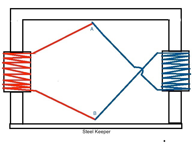
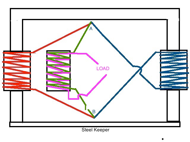
    I particularly like your schematic#3...have you ever tried to make a small motor out of this circuit?

    I believe with all the four coils above (and of course a different distribution) we could make a nice small motor where the switch would be a small 3 element commutator plus a couple of brushes to close circuit at a particular angle where a constant (perpetual?) rotation could be produced..

    Anyways that was just a "fly by idea" that came to my mind when I saw your circuit #3...

    But about the main idea, I believe you are completely right for it being used on the TPU main principle.

    IMHO, I believe that Cook's and Figuera's ideas on their Patents were missing this important factor of keeping the cores closed and maybe distribute them in "MODULES" which could be connected together just as batteries to add up bigger energy outputs...but maybe they did it on purpose, not to show a FULL PATENT Diagram...idk and guess no one will ever know the truth.

    That is the reason why, now I am building a toroidal structure for the Figuera generator primary-secondary Cores...which would eventually be just "one module"...

    Back on your idea...I believe that reminiscent field generating a continuous flux around the closed core would do create an Electric Field(EF) indeed...However, I believe that EF besides being weak, it will eventually decay over time SINCE We are not EXCITING anymore the Magnetic Field which actually was the one who originated the EF ("Excitement" as "producing a CHANGE" paraphrasing Faraday Induction Law)...

    But parting from the main principle, that we have a Permanent Magnetic Field within a Closed Core, even being "stationary" (meaning not excited, not "changing")...I believe that creating even a small "change" would be very cheap "to pay for" with very high expectancy on the output...and of course, backed up by Caps to make an LC Closed Tank Circuit...etc,etc.


    I believe here, you have simply "touched" the really HOT BUTTON, that could trigger the Free Energy Generation!!


    Thanks again.


    Ufopolitics
    Last edited by Ufopolitics; 02-20-2018, 06:12 PM.
    Principles for the Development of a Complete Mind: Study the science of art. Study the art of science. Develop your senses- especially learn how to see. Realize that everything connects to everything else.― Leonardo da Vinci

    Comment


    • #17
      Not to discourage people from looking but there are some really fundamental things to take into consideration.

      First the PMH works because there is no loss in the inductor. Hysteresis, eddy currents and BEMF all show up from the modulation of the magnetic field and/or from the introduction of current into the windings of the inductor which produces a magnetic field. This has none of that, except on the initial charge. The magnetic field is simply free flowing in a circle. Without directional change no magnetic loss is induced. Not even flux loss would not be present, IE Sharp Corners. That kind of flux leakage is again caused from alternating direction and is stored flux from the previous cycle collides with new income incoming flux.

      Now David says the transients or inductive collapse are what add the power but really with this setup you should be looking (IE with scope) for only one thing. The rate of charge on the center coil and any modulation that it brings.

      This should be viewable on the center coils CLOSED winding if the magnetic wire is striped of insulation and you probe across it and look for peak voltage. The closed winding on the center coil cannot charge without causing a small rise in voltage. That should be present as it raises the voltage just before evacuating the coil. IE a potential difference that allow the current to flow back out through the resistance of the windings.

      If you can find that modulation which has to be there you set your switching on the open winding of the coil to interact at peak voltage of the modulation.
      IE coil shorting.

      Coil shorting in generators reduces the lenz effects and can raise the overall output of a given coil. If you have looked at it seriously you know this to be true even though the gains are minuet. If you haven't well call me a liar and I'll call you lazy.

      Depending on the size and frequency of that closed winding you most likely could set up a simple monitoring ADC from an Arduino and drive the switch's via a predictable variable. If the frequency is below 1 MHz you could possibly switch several times per rise in voltage. If you have real good hold this, after, or if you find it you can set that coil up for a predictable behavior. Very simple math to look at the rate of change in the coil can give you predictable results from just a voltage reading.

      From everything David has told me about it that seems to me to be the best approach to watching the output gain at least in flux density. Remember its about effect, Find the effect manipulate it then worry about measuring and getting work done from it. I would consider a PMH that held an ever increasing rate of weight before the bond was broken to be true free energy device that does work. No matter the time it took to see results.

      Matt

      Comment


      • #18
        Power supply

        OK, I used a 5 1/4" diameter toroid Clarence sent me and some left over wire. Both coils are same size and 120 ac 60 hz primaries. The single coil is bifilar parallel wound with iron core. I do have welding rod material to try also.

        Which power source do I use? PWM dc, mains AC, Booster DC, I had a signal generator but not now. The spare parts I had laying around. Please no negative comments, but rather positive and forum like teaching. I don't mind testing if anybody wants to explore this farther.


        28418127_1830681973629299_2142229270_o.jpg

        wantomake

        Comment


        • #19
          I was thinking about trying this with a large ferrite toroid that is cut in half but I'm not sure if ferrite is the best thing to use for this. Maybe soft steel is better? Also would like to ask when winding coils whether they would be best wound in bucking mode or aiding mode direction? Any thoughts on that welcome.
          There is no important work, there are only a series of moments to demonstrate your mastery and impeccability. Quote from Almine

          Comment


          • #20
            Originally posted by ewizard View Post
            I was thinking about trying this with a large ferrite toroid that is cut in half but I'm not sure if ferrite is the best thing to use for this. Maybe soft steel is better? Also would like to ask when winding coils whether they would be best wound in bucking mode or aiding mode direction? Any thoughts on that welcome.
            Hello Ewizard,

            I also have a ferrite square core split in two equal parts that I took off a big TV HV Coil...I am gonna test it, even though ferrite is designed for HF, as I believe it does not have good retention properties (not sure though, have to look it up)...still I would use it on this plus other projects.

            On the winding mode I believe the aiding type would be the right way, since N-S would provide a continuous Flux path with same magnetic spin.

            Either way, after is done, changing to bucking and then testing only would take to reverse one of the two coils terminals.

            Just my opinion on this, hope it helps you.


            Regards


            Ufopolitics
            Last edited by Ufopolitics; 02-23-2018, 06:27 PM.
            Principles for the Development of a Complete Mind: Study the science of art. Study the art of science. Develop your senses- especially learn how to see. Realize that everything connects to everything else.― Leonardo da Vinci

            Comment


            • #21
              Originally posted by Ufopolitics View Post
              Hello Ewizard,

              I also have a ferrite square core split in two equal parts that I took off a big TV HV Coil...I am gonna test it, even though ferrite is designed for HF, as I believe it does not have good retention properties
              You are right in that this type of core is designed not to have remnance. A better toroid material would be to try a tape wound square loop type of core, which were used in small inverters in the 60's and 70's. "Square loop" refers to the B-H curve shape, not the core itself. The remance is almost as high as the Bsat value.

              Comment


              • #22
                Thanks UFOPolitics - always good to hear your thoughts. And thanks Serendipitor for your input too.

                Has anyone done any tests yet with this concept? I think I've got everything I need to give it a try if only the time thief will stop stealing all my time
                There is no important work, there are only a series of moments to demonstrate your mastery and impeccability. Quote from Almine

                Comment


                • #23
                  Energy IN does NOT equal Energy OUT most of the Time

                  Originally posted by mbrownn View Post
                  A very thought provoking set of questions.

                  Can you get a gain from an inductive spike?

                  Of course you have to do some work to create a spike and the return is less than what you did to create it under ohms law. The thing is, both the work you put in and the return spike both create magnetism which can do work. Now the question is this. Is the energy in the work done by the magnetic field more than or less than the initial work put in?
                  If you make the magnetism do work does that reduce the power of the return spike?
                  Is the work done by magnetism and the return spike more than the power you put in? I believe it is.

                  Using maths it would suggest that the energy available in the magnetism of the input and return spike is double the input less what is lost to ohms law, but the moment we start making that magnetism do work our return spike reduces. This may be a disappointment but the reduction does not appear to be proportional. Why is this? because the magnetism is at 90 degrees to the current doing the work. I figure that the power available is the line (Hypotenuse) going between the input and the work done. Im not very good at explaining it but its like reactive power being added tangentially to the input power.

                  Can you get a gain from a transient spike?
                  This is interesting because no spike is truly transient, so the answer must be yes. How much? I dont think there is a lot to use directly but there may be benefits in translating them through a battery.

                  Can you get a gain from the change in flux from a magnetic field if you do NOT "pay" for the change?
                  Yes. I assume this relates to the collapse of the field and your first question.

                  Can electrical energy be trapped or stored in a coil?
                  I dont think so, I believe a coil to be a translation device that takes one form of energy and turns it into another.

                  The lockridge device may be an interesting model on which to test these points.
                  By passing a current through the coils a magnetic force rotates the armature. The moment the current is cut off the coils provide a spike which if given a path, allows current to continue flowing in the same direction. This current also provides a magnetic field and continues to rotate the armature. 2 for one less ohms law.
                  This current flow can also be collected in a capacitor. 3 for one less ohms law.
                  But is the energy in parts 1, 2 and 3 real? yes. The initial current did work so the inductive kickback current must be new and not stored energy in a conventional sense.

                  The initial current after it has passed through the coils can be stored in a capacitor or battery. The energy in it is equal to the input less ohms law.

                  As the coil has done work the inductance changes so the output from the inductive kickback is not what you would expect from a free coil doing no work, however; current does flow and a magnetic field is created which also does work and this second current can also be stored in a battery or capacitor.

                  If you use a capacitor to store energy, half the energy is lost due to efficiency. Much better to use a battery or use the current directly but that isnt always possible.

                  If our motor is 40% efficient at producing mechanical work, and we gain 30% from the inductive kickback we end up with a 70% efficient motor. This is exactly what happens when using a Universal motor on PWM provided the frequency is correct and the duration of the pulse is less than 60% I think this proves point 1.

                  The energy that passed through the motor and is stored in a capacitor can be anywhere from 30 to 70% of the input. If the mechanical efficiency is 70% then it should be impossible to get more than 30% in the capacitor.

                  Inductive kickback alone produces 15 to 17% which allowing for capacitor efficiency is 30 to 34% which when added to the mechanical is 100% so where has ohms law gone? We do get heat so ohms law is still there and we are over 100%.

                  I could go on but there is a lot to think about there.

                  Hope this gets you thinking
                  Eric answers this question, but in a different context: not magnetic, but dielectric...
                  Eric Dollard - History and Theory of Electricity - YouTube

                  ...in that energy passing through a capacitor to get to the other side of space, namely counter-space, is not the same energy coming back out of the dielectric (of a capacitor) from counter-space. And, thus, the two energies are not equivalent. One can be greater than or less than the other.

                  I have a guess why...

                  Whenever the square root of a value on an oscilloscope tracing is taken, it can yield two right answers if each is affiliated with two unique waveforms giving two new identities different from the parent waveform which preceded them. Multiplication of waveforms induces a need for more energy to embody more waveforms while the elimination of waveforms has the opposite effect. The energy to embody the increased population of waveforms has to come from somewhere, but who has an imaginary meter to read imaginary values in counter-space? -- Pun intended, ie. a meter that can read complex numeric values of mixed real and imaginary parts.

                  Lewis Carrol's "Through the Looking Glass" is a very apt metaphor for the dielectric property acting as a portal negotiating between space and counter-space. I suspect coils act as bidirectional pumps that will determine whether energy is going to leave the circuit or enter into it from the aether and to what degree in each direction from moment to moment.

                  Thus, the expression...
                  Energy IN equals Energy OUT

                  ...does not pertain to the majority of forces governing the dielectric and magnetic fields, but merely thermodynamic conversions and losses.

                  As an aside...
                  The attached file, below, is excerpted from pg.110 of Eric's presentation to the San Francisco Tesla Society and contains a PMH at its core. It has proven to be an enhancement (maybe the PMH is the reason why?), of Eric's simpler LMD analog computer given out during his Borderlands video from 1988, when used for the amplification of an initial operator input of energy to start a surge toward infinity (at least undergoing simulation in a browser's JavaScript or in Java using CircuitMod).
                  Attached Files
                  Last edited by Vinyasi; 02-26-2018, 02:16 AM.

                  Comment


                  • #24
                    Originally posted by Vinyasi View Post
                    Eric answers this question, but in a different context: not magnetic, but dielectric...
                    Eric Dollard - History and Theory of Electricity - YouTube

                    ...in that energy passing through a capacitor to get to the other side of space, namely counter-space, is not the same energy coming back out of the dielectric (of a capacitor) from counter-space. And, thus, the two energies are not equivalent. One can be greater than or less than the other.

                    I have a guess why...

                    Whenever the square root of a value on an oscilloscope tracing is taken, it can yield two right answers if each is affiliated with two unique waveforms giving two new identities different from the parent waveform which preceded them. Multiplication of waveforms induces a need for more energy to embody more waveforms while the elimination of waveforms has the opposite effect. The energy to embody the increased population of waveforms has to come from somewhere, but who has an imaginary meter to read imaginary values in counter-space? -- Pun intended, ie. a meter that can read complex numeric values of mixed real and imaginary parts.

                    Lewis Carrol's "Through the Looking Glass" is a very apt metaphor for the dielectric property acting as a portal negotiating between space and counter-space. I suspect coils act as bidirectional pumps that will determine whether energy is going to leave the circuit or enter into it from the aether and to what degree in each direction from moment to moment.

                    Thus, the expression...
                    Energy IN equals Energy OUT

                    ...does not pertain to the majority of forces governing the dielectric and magnetic fields, but merely thermodynamic conversions and losses.

                    As an aside...
                    The attached file, below, is excerpted from pg.110 of Eric's presentation to the San Francisco Tesla Society. It has proven to be an enhancement, of Eric's simpler LMD analog computer given out during his Borderlands video from 1988, when used for the amplification of an initial operator input of energy to start a surge toward infinity (at least undergoing simulation in a browser's JavaScript or in Java using CircuitMod).
                    you lost me there can you put that in layman’s terms?

                    Comment


                    • #25
                      If I'm not mistaken...

                      Originally posted by mbrownn View Post
                      you lost me there can you put that in layman’s terms?
                      The discussion, here, is whether or not (or how if possible) a PMH can be used for overunity gain? Am I right?

                      Well, to bypass my terse summation of what I got out of listening to that presentation of Eric's over and over again, is epitomized by a single image extracted from out of one of his powerpoint presentations in which a PMH is at the core of an analog computer (emulation) of a transmission line. This analog computer is normally used for analyzing a transmission line without having to build the whole darn thing, but shrink it down for bench testing. But as dR-Green has pointed out, this is also an analog of Tesla's Magnifying Transmitter since it can measure the performance of a TMT while it is running without getting in the way of its activity. I take it that dR-Green should know since he sells plans for miniaturized TMTs.

                      For every circuit we could possibly dream up, there are infinitely many more varieties that will execute that exact same behavior according to Thevenin equivalency.

                      To rephrase my terse summation, studying Eric Dollard's LMD module is an exercise in critical judgement. I've done numerous simulations over the past year which, although many if not most are not practical or buildable, nonetheless they have helped me to grapple with this simple little archetype of Eric's. And now, after spending a year of many hours of trial and error not knowing how to implement Eric's LMD module, and after listening to this important lecture of his (linked, above), I get it. It makes sense due to what I've seen happen in the context of my simulations: behaviors that for lack of a simple explanation, Eric's proves to be very appropriate. But I had to have this experience before anything he says on this topic could possibly make any sense at all. It never has. Yet, during that lecture, he says: just go and build it. Anything. Get experience. And then turn to Eric for organizing the brain around his view of what our experience has brought to our observations.

                      HINT -- Click on the Circuit Information button in the upper right corner and then compare that image with two instances of it being used along the central vertical spine of this simulation.

                      Is there something I overlooked?
                      Last edited by Vinyasi; 02-26-2018, 03:06 AM.

                      Comment


                      • #26
                        Originally posted by mbrownn View Post
                        you lost me there can you put that in layman’s terms?
                        As Eric says in that lecture, each of the two forces of magnetism and dielectricity is in denial of the other.

                        Well, it appears to me that the PMH is in complete denial of dielectricity or else how could it preserve a magnetic charge indefinitely? But this is also the crux blocking its liberation to provide work.

                        As an example, my lightning oscillator simulation makes use of a derivative of Eric's LMD analog computer at its core while an additional two sub-circuits branch off from that core using analog switches in a frozen condition of non-toggling. This helps to make use of the LMD core without violating its behavior.

                        I've done other simulations which flip-flop those analog switches in a continuous manner. But isolation of the core is still essential to its operation.

                        It's a bit of a stretch to imagine that the core of Eric's refined LMD is a PMH when in reality it is merely two coils linked by two wires and each coil has its own iron core distinct from the other and not necessarily in toroidal form. But, it does exhibit the archetype of a closed magnetic loop since two coils are at its foundation just like the one or more coils of a true PMH.

                        For the purposes of illustration of archetypes, this is close enough of a similarity to exhibit that property of magnetism which functions in complete denial of its opposite dielectricity.

                        I'm not suggesting that an LMD module is the solution to this quandary. But I am suggesting that something similar, archetypally speaking, will address this situation in one Thevenin equivalent manner or another.

                        Comment


                        • #27
                          Marc Belanger's PMH

                          cut and pasted from...
                          https://www.youtube.com/watch?v=fIrBYMHtq3M

                          Marc Belanger
                          1 year ago
                          I figured something out that is really cool and could result free energy for anybody who builds this. I took a piece of round soft iron bar stock and bent it into a U shape, leaving the two parallel pieces evenly spaced at 1" from the U all the way to the end. I kind of leaned towards the Ed Leedskalnin device theory but completed the project with my own detail and ideas. I wound a very heavy duty coil on one side of the horseshoe,. and another coil the opposite way on the other side, connecting the wire in the middle.

                          The horseshoe is 8 inches long, and the windings are 240 turns each, with number 20 awg magnet wire. I wound them along the length of the horseshoe and left 3 inches of space unwound at the end, so the windings were 5 inches long, connected at the top of the "U" in an anti lenz configuration.

                          I mounted the U to a wooden frame and bolted it to the metal frame for the rotor to spin inside of the U with the magnets facing the insides of the rounded faces, allowing very little drag and much overunity.

                          This I am giving away as an open source free energy design. Please tell everybody about it and share the diagram.

                          I ask for nothing to use or experiment with, however it has been added to one of my sites and I do own the design. If it is sold, I wouldn't be very happy. I also have rights to this since it has been saved online, so please just use this for free electricity and don't go selling it! Please pass that message around !!

                          Comment


                          • #28
                            Originally posted by Duncan View Post
                            EL tells us to use 'soft Iron' alas thats not readily available now as it was in Ed's time...
                            I did some work a few years ago and concluded that the material that some architects use for driving piles for the foundation of buildings can be iron. Steel is no good; it will rust.

                            Comment


                            • #29
                              Oscillating Power is a Hysteresis of Duty Cycle Imparting an Illusion of Free Energy.

                              I think I misunderstand oscillations when I made this video. I think I mix it up with alternations.

                              A commenter on YouTube just posted, but it didn't go through to the video. But it got me to read the video's description I wrote a year ago which got me to thinking along a previous line of reasoning which may be valid to reconsider: that free energy is a misnomer if our understanding is, indeed, inadequate.

                              That description of mine is appropriate for this thread, because it proposes a concept which may help explain: why my derivative of Eric's analog computer requires a magnetic core to its coils and possibly help to suggest why each module must not be shorted between each adjacent module as Eric demonstrates in his now famous Borderlands video with Thomas Brown and Peter Lindemann from the 1980s...
                              https://www.youtube.com/watch?v=6BnCUBKgnnc

                              It may be appropriate, because it proposes that the magnetizable core of a transformer (or PMH) does not forget its state despite its use by its two coils implying that coil induction entering into a coil is expendable while core induction exiting the core and transferred to the coil is never fully expended or may not be expended at all allowing the core to retain its charge producing an endless supply of induction for the transformer's coils.

                              Here is the video link...
                              https://www.youtube.com/watch?v=L8klrsqHCOM

                              And here is its description...
                              I don't think that my little simulation of Eric Dollard's LMD (analog computer in Longitudinal Magneto-Dielectric mode) actually produces power inside the LMD module when the AC power source is shut OFF. Actually, I think that each cycle of oscillation begins before the last one ends building upon the prior and gaining a little more amplitude with each successive cycle giving the appearance of energy from the vacuum - energy created from nowhere. But it sure does look - for all intents and purposes - as if that is what has occurred whenever certain switches are engaged and others are not. I don't remember which ones. You'll have to play around with it...

                              https://is.gd/BL_LMD_v1d
                              https://is.gd/blankcanvass

                              I hope to do a chart of all eight possible combinations of switchings and their outcomes. In the meantime, I'd like to share with you what I went through the very first time I simulated free energy in disastrously humongous proportions...

                              https://is.gd/extreme_overunity
                              https://is.gd/blankcanvass

                              https://is.gd/WIPEOUT

                              https://is.gd/extreme_overunity2
                              https://is.gd/blankcanvass

                              In both of these two varieties of Extreme Overunity, a strange anomaly occurs. You think you're being dandy by shutting OFF the AC power to prevent any further mischief, but what happens? The amps, volts, and watts skyrocket even faster than when the AC power had been ON! No fooling!

                              And where does this escalation occur? EVERYWHERE in the circuit!!!! Now, that's indiscreet OVERUNITY!

                              Here is a very simple version of this basic concept with only four switches and a modest, rock solid output hanging around the kilo-volt range. Two additional loads are added to the inside of the LMD module...

                              https://is.gd/4switches
                              https://is.gd/3lamp_LMD

                              This is a very long video describing my inspired thinking on why some of us are convinced that free energy arises from out of nowhere – whenever it occurs as the result of oscillating power, but actually comes from hysteresis originating in the NEGATIVE RESISTANCE of a GAS DISCHARGE TUBE, or SPARK GAP, and then spreads throughout the circuit infecting everything including the load due to HYSTERESIS becoming applied to all of the components of the circuit (including the load - which is attached and must be included). This pervasive hysteresis is the byproduct of severe stress shocking the whole circuit to sustain the belief among all of the circuit's various components that they, too, are NEGATIVE RESISTORS just like the spark gap.
                              I added a pinned comment to aid the video's description...

                              The circuits for this discussion are five circuits underneath the category called: "Complex Manual Switching" underneath my category called: "Vinyasi.Cts" pasted to the menubar of my mirrored spin-off of Paul Falstad's electronic simulator located here...
                              http://vinyasi.info/ne

                              http://vinyasi.info/ne?startCircuit=...ing-design.txt Θ* First Manual Switching Design
                              http://vinyasi.info/ne?startCircuit=...design-v1d.txt Θ* First Manual Switching Design, v.1d
                              http://vinyasi.info/ne?startCircuit=3lamp-lmd.txt Θ 3 Lamp LMD
                              http://vinyasi.info/ne?startCircuit=...ulse-vs-dc.txt Compare Pulse vs DC Voltage Source
                              http://vinyasi.info/ne?startCircuit=kaboom.txt ∞# Pulsed EV Motor Experiment

                              based on...
                              http://vinyasi.info/ne?startCircuit=...eakthrough.txt Θ*∞ First Breakthrough in OverUnity
                              http://vinyasi.info/ne?startCircuit=...akthrough2.txt Θ*∞ First Breakthrough in OverUnity w/2 Lamps
                              ...underneath the "Vinyasi.Cts" category called: "Breaking Free of B&L w/LMD" called: "Θ*∞ First Breakthrough in OverUnity" and "Θ*∞ First Breakthrough in OverUnity w/2 Lamps".
                              Plus, I took a little bit of liberty by adding his comment...

                              michael R
                              https://www.youtube.com/channel/UCCA...-_TCrUhc-o-dqw
                              I was worried someone wasn't going to debunk this one so thanks foot that even though your the only one that has, no I didn't watch the entire hour and some odd video but I love how the circuit in the thumbnail is totally wrong from Eric's original circuit also I feel sorry for everyone that doesn't believe in dare I say "free energy" lmfao guess what its very real anyways I hope I can put someone back on track with my words. Good luck out there we all need it.
                              This is a very long video. Requires a lot of patience to put up with my yada, yada-ing....
                              Last edited by Vinyasi; 03-26-2018, 02:39 PM.

                              Comment


                              • #30
                                Origins of the Perpetual Motion Holder

                                You all might be interested in this - the origin of the Perpetual Motion Holder:

                                Perpetual Motion Holder Origins - A & P Electronic Media
                                Sincerely,
                                Aaron Murakami

                                Books & Videos https://emediapress.com
                                Conference http://energyscienceconference.com
                                RPX & MWO http://vril.io

                                Comment

                                Working...
                                X