Announcement

Collapse
No announcement yet.

Gadgetmall Coanda OU UFO.

Collapse
X
 
  • Filter
  • Time
  • Show
Clear All
new posts

  • #16
    Magnet wave.

    JLN tests an output coil on a ferrite core, and calibrates the distance in centimeters from the magnet rotor for peak efficiency: Here's a video of his test:

    https://www.youtube.com/watch?v=YUoyuiQTrRA

    "Normal Lenz effect can be reversed"

    At 30 centimeters distance along the ferrite core from the rotor, the output coil seats over the peak of the "Magnet Wave".

    This distance in very small increments of centimeters, makes all the difference in the output! Same goes for "Gadgetmalls "Piggyback" output coil.

    The GIF on the right shows the flux traveling through the core: At the sweet spot "Lenz drag" turns into "Lenz propulsion"'
    Last edited by Allen Burgess; 10-07-2019, 10:02 PM.

    Comment


    • #17
      Piggyback kickback.

      The "Piggyback Output Coil" generates a current from the magnetic core; Consequently, this new current in the output coil generates it's own magnetic field. This field travels back into the ferrite core. Properly positioned on the ferrite core, the "Piggyback Output Coil" sends a magnet wave back through the core which couples simultaneously with the power coil pulse, accelerating the magnet rotor and reducing input.

      The correctly positioned "Piigyback Output Coil" not only collects and redirects the power pulse "Flyback" toward return to source; It sends a reflected magnet wave back through the ferrite core that helps power the rotor and reduce input. So there's a "Twofold" advantage.


      JLN demonstrates "Lenz Reversal" with his output coil separated from his power coil. JLN's separated coils do nothing to conserve and loop the power coil BEMF, as "Gadgetmall's coupled coils do.
      Last edited by Allen Burgess; 04-24-2017, 01:35 PM.

      Comment


      • #18
        "Lenz Reversal"

        Quote from JLN's video posted above:

        "Here an interesting experiment about the Delayed Lenz Effect which shows that the normal Lenz effect can be reversed"

        JLN starts off with his stator coil 1 mm from the magnet rotor. He shorts the coil and the rotor slows down and the input rises. (Normal Lenz Drag effect)

        JLN then moves the stator coil back on the core to a distance of 30 mm from the magnet rotor and shorts the coil a second time. The rotor speeds up and the input drops. (Lenz reversal effect)

        Fusionchip's "Piggyback stator Coil" is free to move along his ferrite core just like JLN's. The position of Fusionchip's piggyback coil can generate "Lenz Reversal" just like JLN's output coil at the "Wave Reflection Distance"!

        The major difference between these two setups is that Fusionchip's power coil shares the ferrite core with the power coil and is not separated from it like JLN's. This gives Fusionchip's "Piggyback Output" coil the additional advantage of generating power from "Flyback" pulse recovery. This twofold advantage apparently resulted in a demonstrated overunity loop. This "Lenz Reversal" effect was poorly understood at the time of Fusionchip's video.
        Last edited by Allen Burgess; 04-30-2017, 12:18 AM.

        Comment


        • #19
          Wave reflection zone.

          The distance between the piggyback coil and the beginning of the ferrite core needs to be exactly on the magnet wave peak to achieve "Lenz Reversal" along with BEMF recovery. The "Piggyback Output Coil" generates A.C. current and needs a full wave bridge rectifier to loop to the D.C. source. This combination of "Lenz Reversal" and and "Flyback Recovery" add up to Overunity. A simple Reed switch would run this hybrid ferrite core coil combination just fine. The rotor magnet polarity needs to be N S in order for this effect to work.
          Attached Files
          Last edited by Allen Burgess; 04-29-2017, 06:14 PM.

          Comment


          • #20
            Barkhausen effect

            The magnet wave in the soft iron core is compared to a sloshing tank of water by JLN on the left; On the right is a graph showing the wave peak in conjunction with rotor magnet TDC for "Lenz Reversal":
            Attached Files
            Last edited by Allen Burgess; 04-29-2017, 06:15 PM.

            Comment


            • #21
              "N-S Brushless Motor Circuit".

              Gadgetmall's running a monopole Bedini SSG with all magnets pointing North out. JLN's tests are with a dipole or N-S magnet rotor. Let's take a look at this 4 coil brushless N-S magnet motor circuit with one Hall effect sensor and two NPN transistors:

              John Bedini designed this kind of circuit with Cole, but it has his "Flyback Catcher" circuitry and the additional battery. We don't need a special flyback recovery circuit because the "Piggyback Coil and Ferrite Corel" does that for free through induction. This brushless motor circuit is very simple by comparison:

              1 diode, 2 pairs of matching resistors a matching pair of NPN transistors, 1 Hall effect sensor and 1 tiny capacitor!
              Attached Files
              Last edited by Allen Burgess; 04-29-2017, 10:26 PM.

              Comment


              • #22
                "Bedini's Sequential Circuit".

                Just for quick contrast we can see how complex John's "Sequential bipolar switch-commutator" circuit is with 7 transistors, PNP and NPN for only 1 coil:
                Attached Files
                Last edited by Allen Burgess; 04-29-2017, 10:23 PM.

                Comment


                • #23
                  Ferrite Core

                  JLN speaks of his ferrite core:

                  "I have used a soft iron core (120 mm length, 8 mm diameter)".

                  That's 4 3/4" long! We will probably need at least 7" in length to accommodate the power coil, and still have the additional core length to get the proper wave reflection distance.

                  The 14 inches and a 6" rotor would give the Coanda Craft just under a 2 foot diameter at the base. Very nice size. We can place the 4 coils on the floor along with the rotor and simply extend the length of the drive shaft up to the fan cage overhead.

                  Hooking these kinds of coils and brushless fan circuit up to an alternator would allow you to run your house for free also.
                  Last edited by Allen Burgess; 04-29-2017, 10:48 PM.

                  Comment


                  • #24
                    Hall effect sensor.

                    Here is a definition of the sensor operation:

                    "The Hall effect provides information regarding the type of magnetic pole and magnitude of the magnetic field. For example, a south pole would cause the device to produce a voltage output while a north pole would have no effect. Generally, Hall Effect sensors and switches are designed to be in the “OFF”, (open circuit condition) when there is no magnetic field present. They only turn “ON”, (closed circuit condition) when subjected to a magnetic field of sufficient strength and polarity".


                    Below are a schematic of JLN's circuit and his Hall Effect Sensor:

                    This "Hall Effect Sensor" triggers on the south pole while the north pole has no effect! It appears that JLN's power pulse is hitting the North pole of the magnet , and that the "Reflected Magnet Wave" is hitting the South pole.
                    Last edited by Allen Burgess; 05-18-2017, 07:03 PM.

                    Comment


                    • #25
                      Brushless Hall Effect Sensor.

                      It appears that the brushless Hall effect Sensor triggers on one pole of the magnet just like JLN's, but it's "Latching" so it stays on until it's turned off by the opposite pole.

                      Here's a good video demonstrating the difference between a "Hall Effect Switch" and a "Hall Effect Latch" and the third type:

                      https://www.youtube.com/watch?v=9BFdGtvo9JE


                      JLN is using a "Linear Differential" Hall effect sensor, the third type in the video, which is very sensitive.
                      Last edited by Allen Burgess; 05-18-2017, 03:23 PM.

                      Comment


                      • #26
                        Hall Effect Sensors.

                        I think it may help to replace the "6851 Hall Effect Sensor" used in the brushless motor circuit, with the " UGN 350 3U Linear Differential" type JLN used for his tests. This would mean we would have to switch the two transistors from NPN to PNP types.
                        Last edited by Allen Burgess; 04-30-2017, 01:21 PM.

                        Comment


                        • #27
                          JLN's circuit

                          The soundest approach to test this Overunity power recovery coil, is to simply use JLN's basic circuit to start. The four components are listed in the schematic:
                          Last edited by Allen Burgess; 05-18-2017, 03:24 PM.

                          Comment


                          • #28
                            Can I just jump in to the middle of this because I'm reading your posts and it isn't clear to me that what you're proposing is aerodynamically sound. I realize you may already be aware of these things. The Coanda Effect is simply the nature of air or a fluid to follow a curved surface. It doesn't mean it will follow it around a bowl in a spiral curve. If the fan only blows on one portion of the saucer it will only follow that one area down and off the saucer generating a force in that direction.

                            The Coanada Saucer is an idea which is typically less efficient than a pure ducted fan, an certainly less efficient than a helicopter. However, it has qualities which neither of the other two do and which make it attractive. The attraction to the Coanda Saucer is primarily safety combined with vertical capability. Hopefully this all makes a little sense. Not sure, but hope it does. Now this doesn't mean a Coanda cannot be an efficient lifting machine, it's just that as of recent it has never been developed sufficiently to make one that is. Far be it from me to disuade you from what you're doing and I just want to make sure you understand what is going on aerodynamically.

                            A well designed ducted fan features a lip along the leading edge, and which is an airfoil, and which wraps around the upper edge of the duct. Thus the air moving through the duct is moving air over an airfoil, and which is itself like the leading edge of wing bent in to a circle. The air is then moving over a leading edge of circular wing as it enters the duct, and which produces a lift whose vector force is upwards.

                            An example of a well designed ducted fan is the Hiller Flying Platform. This machine happens to also be the most stable flying machine every invented. In fact it's so stable that it is hard to make fly in a straight line because it keeps trying to right itself.

                            So a well designed Coanda Saucer is itself a wing which has a mechanically driven air stream blown over it. It doesn't circulate around it. The air moves across and down with the curvature of the saucer, and that curve represents a cross section of an airfoil.

                            Thus the speed of the airstream which follows the shape of the saucer is important in determining factors in the saucers hull shape.

                            In a way a Coanda Saucer is the reverse of a helicopter rotor. A helicopter rotor is a big slow rotating wing, and again it's driven forward by a mechanical motor. The wing moves in to the relative wind by force of mechanical transmission. Whereas, in the case of the Coanda, there is a small propeller instead of a big rotating wing, and to replace that big relatively slow but dangerous rotating wing most Coanada Saucers have used a ducted fan to blow air down and over the saucer shape which is then a wing which doesn't move at all. This is much safer than any helicopter whose main rotorblades are typically countered with an anti-torque high speed tail rotor that is legendary for beheading people. So a Coanada Saucer is vastly safer in tight places and where there may be people or other creatures that may wander into the blades. Whereas, the Coanda uses a ducted fan propeller safely tucked way overhead, and which forces a mechanically driven stream of air across a wing which doesn't move at all.


                            See this material.

                            http://www.coanda.co.uk/Assets/Coand...for%20UAVs.pdf

                            Coanda disk aircraft research site.


                            Now see this material because maybe...maybe...it is possible to make a Coanda Saucer which uses the system you're working on because a glow discharge plasma control system does invite the idea of guiding the airstream precisely where and how you want it to go. This one atmosphere system isn't very complex either.

                            One Atmosphere Glow Discharge Plasma Control Surfaces
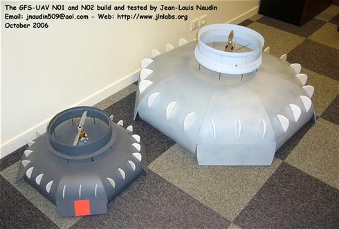
                            Towards the UAV N-XX, an EHD Coanda flying saucer by Jean-Louis Naudin

                            Jean-Louis Naudin is probably the first person to make an actual Coanda Saucer in probably the last 40 years. For that he deserves a great deal of credit for the interest it generated, but what he wants and what we all want is more than this ducted fan machine has delivered so far. It's a good machine which can be improved on.

                            The coanda saucer here built by Jean-Louis Naudin. Dr Stephen Prior at Middlesex University independently tested these and found that there is no additional lift which resulted from the shape of the body. In fact the lift provided by the propeller alone was greater without the body.
                            https://www.cfd-online.com/Forums/ma...duce-lift.html


                            [VIDEO]https://www.youtube.com/watch?v=sdGVI7kJld0[/VIDEO]
                            Last edited by Gambeir; 05-01-2017, 06:56 AM.
                            "The past is now part of my future, the present is well out of hand." Joy Divison "Heart and Soul LP."

                            Comment


                            • #29
                              Originally posted by Allen Burgess View Post
                              "The Coandă effect is the tendency of a fluid jet to stay attached to a convex surface".

                              This video shows a non-vortex centrifugal air blast over a "Coanda Hull":

                              https://www.youtube.com/watch?v=aF92B6Gon3M

                              :


                              This explanation in this Youtube video is not accurate at all. Not even remotely close. This isn't why air flows down over the bowl. Neither is the Coanda Effect a phenomena as some like to say officially, mainly on google searches, though once upon a time it was considered a phenomena.

                              Today we know that a boundry layer of particles adhears a jet of air to a convex surface and which is defined as a the Coanda Effect when that flow of air follows the curvature of a surface away from the direction of the originating airflow. This is to say then that a jet of air will follow a convex surface.
                              Last edited by Gambeir; 05-01-2017, 07:21 AM.
                              "The past is now part of my future, the present is well out of hand." Joy Divison "Heart and Soul LP."

                              Comment


                              • #30
                                Ducted Fan

                                @Gambeir,


                                Firstly, I want to thank you for all the updated links. I wasn't aware of JLN's Plasma control advance.

                                I'm trying to design a toy from the dollar store, based on a paper mache hull formed over a blow up balloon.

                                The ducted fan looks great compared to the centrifugal fan. I wonder how come no one's ever actually built one?

                                This ducted fan looks great, but all we need are two thousand Japanese engineers, not a ten dollar swap off ebay!

                                The outer Hull of my "Coanda Craft" has to be free to spin. I discovered this effect while experimenting with a compressed air vortex helmut made from a PVC end cap. You pointed out that the funneled vortex from the centrifugal fan would not spiral down around the Hull. You're correct. I didn't go into this effect tat any great length, but I can assure you that it worked fantastic.

                                This is an entirely new undemonstrated effect that I stumbled upon accidently through bench test experimentation. The "Spinning Hull" itself acts as a giant propeller. Only the skin needs to spin! This is why the "Spin Hull Coanda Craft" needs an internal counter rotating mass.
                                Last edited by Allen Burgess; 05-07-2017, 01:43 PM.

                                Comment

                                Working...
                                X