Announcement

Collapse
No announcement yet.

Splitting The Positive

Collapse
X
 
  • Filter
  • Time
  • Show
Clear All
new posts

  • Originally posted by RAMSET View Post
    Mikey
    I cannot watch videos too easily ,but I have a question

    if both coils have a total 100 feet of wire ,one single wrap another Bifiler

    are you stating that DC resistance will be half in the 100 feet of Bifiler
    as apposed to the 100 feet in a mono wound coil
    same length of wire ...half the DC resistance ??

    I will delete this comment if I misunderstood
    or at your request

    respectfully
    Chet K
    Hey Ram
    Don't worry about stepping on any of my biggest toes, I forgive
    and forget fast especially after a good ole fashion brawl, it's a man
    thing.

    Good to see you hanging out.

    Yes that is correct according to the video not for 100 feet though.

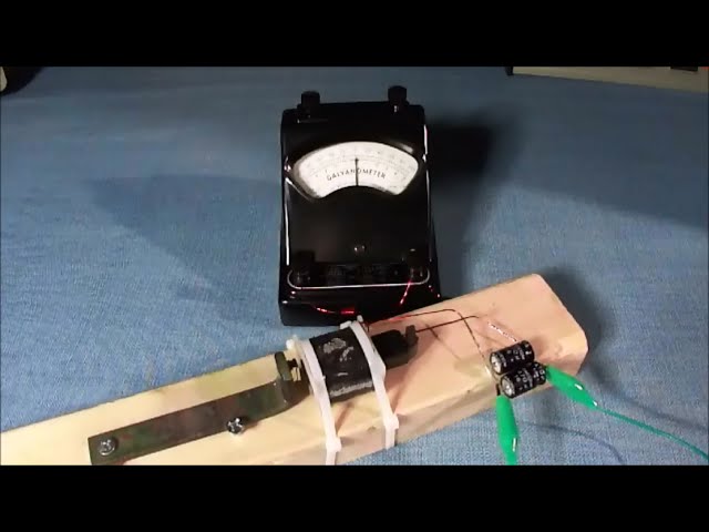
    In THE OLD SCIENTIST video and in the picture the amount of wire
    used was 680 turns of 22 awg wire and the spools looked to be around
    a 2" diameter and with this we might guess the length.

    But I think the awg of the wire is actual less because the feet are
    less than 680 feet. My mistake. I will correct this thought, however
    according to the video measurements THAT spool that looks to be
    about 15" long and approx. 2" diameter holds 680 turns and this is
    what we have to work with.

    Yes that is right Ramset when using the same number of turned
    split up like a bifilar and series connecting the winding, the resistance
    value is not quite half but close enough.

    You really need to see the video. He has been around for years and
    has a lot of nice test equipment. Nice everything, scopes you name it.

    The lower resistance value may be due to the assisted flow as the
    reconnect in series is in the same direction as the first wire flowing.

    Then when watching the video he double verifies everything with
    two other forms of measuring instruments such as the LCR regular
    and then he switched to a precision LCR metering device, then he

    looks at the scope as he runs a generator on the coils to find RES.

    Comment


    • Bro Mikey
      well forgive any sloppy typing ,I had a retinal reattachment surgery in February, and apparently its failing again, going under the knife again
      tomorrow.
      but this question [mine yet to come]and the condition you describe is very very intriguing.

      a friend wound two coils last night after reading your post ,they have the same
      resistance as your example [from the old scientist] ,but they are smaller in size

      His results showed no disparity ??

      he suspects there may be a need to pass a threshold for this to happen ?? [bigger coils... actual replication]
      or that perhaps there was some error in the actual test probe placement ?

      this would truly be an amazing gift ....simply utilizing
      this coil characteristic .

      all my comments here are sincere ,
      have you ever seen this yourself ?
      or know someone who has ?
      I would love to wind some wire on the lathe myself ....
      but seems not for a while...
      respectfully
      Chet K
      Last edited by RAMSET; 04-13-2017, 01:36 AM. Reason: changed improper spelling of key word
      If you want to Change the world
      BE that change !!

      Comment


      • Originally posted by RAMSET View Post
        Bro Mikey


        he suspects there may be a need to pass a threshold for this to happen ?? [bigger coils... actual replication]

        I would love to wind some wire on the lathe myself ....
        but seems not for a while...
        respectfully
        Chet K
        Okay I have briefly reviewed that OLD SCIENTIST says his wire is .5mm
        or .021 " = 24awg so I was wrong on that. Then the length should be more
        like (GUESSING) 7" X 680 turns.

        I will be back. I will ask God to help you with your eye experiment.
        The Lord is kind and gracious showing mercy to all generations.

        Comment


        • Hello Ramset

          I went back and listened very closely and deduced that only
          for one test OLD SCIENTIST connected two ends of his bifilar
          coil together while reading the other two ends or the ends of
          wire on the other side. This is cancellation and forms what is
          known as a HAIRPIN.

          In other experiments I have witnessed that inductance meters
          will read zero using short coils and so a very long coil will read
          almost nothing as in this case. However I can not explain the
          resistance value.

          In most regular series connected paths using the bifilar one side
          might read 50 and the other side 53 which would lead us to think
          both added together should be around 100, when in reality the value
          the readings show as much as twice the assumed value in raw tests.

          Again a few video's back a standard transformer is shown to be
          modified to be used as a bifilar where resistance and impedance
          simply disappears.

          In yet other evidence multi-filar coils shown with various connection
          paths are beyond the scope of simple descriptions. This changes
          everything about the coil so we may have more options to tune
          our coils to meet the need.

          Often shooting in the dark for a specific tuning the right coil setup
          could make quick work of finding the keyhole on the lock.


          Comment


          • I have updated the picture to reflect the most probable data that
            was not available and needed to be filled in. For instance the coil
            diameter was found at 2.35" Dia X 3.14 pie = 7.379" circumference
            so then

            7.379" X 680 turns = 5017" / 12" to get feet = 418 feet of 24awg
            at 26 ohms per thousand feet of 24awg

            So then 418 feet out of 1000 feet gives a value of
            .418 X 26 ohms = 10.868 ohms just like OLD SCIENTIST has.

            Depending on the selected connection path resistance and impedance
            may be greatly reduced that can allow for huge changes.

            The lower frame shows a HAIRPIN connection path. With this circuit
            inductance cancels and many other things can occur.

            As shown by the low figure for this large unit as compared to many
            other much smaller coils that read zero inductance. In this case nearly
            zero inductance but not zero. Approx. 130 times lower than the
            standard solenoid reading.


            Last edited by BroMikey; 04-13-2017, 09:03 AM.

            Comment


            • Okay Ultraman TK has corrected us from YT and this is fine.
              Thx TK for doing some of this work and I say it's okay if the
              results show the same however this does not end anything you
              understand.

              But you are probably right for such a tiny coil. What are you going to
              to with the other measurements such as inductance, surely you must
              has a meter.

              You see while TK is right on static readings during powering tests the
              impedance (A form of resistance) changes dramatically.

              For now i think it is important to show what we probably guessed about
              the standard resistance of magnet wire. Let's start here with TK's
              video.

              TK presents are large cross section of the people who can only see
              the conventional theories and has trouble going outside the box. It's okay
              this is fine, no problem.

              But remember this, if you can read and understand the math I posted
              about bifilar papers written in the 1940's you would realize that this
              is no new data, we are just now learning this, that is all.

              The bifilar math and theory went orbital with the rise of early radio.

              But still, let us start with the obvious and again thanks TK for taking
              the time to address this area of research so we all can investigate
              together on youtube.

              Here is TK on the testing of DC resistance of wire coils.


              https://www.youtube.com/watch?v=fraTy20BAsY

              Comment


              • Okay we will address TK's video later, this has nothing to do with
                dc ohms on a bifilar coil, or does it? You tell me. I am asking all of you
                to think about WHY this Bedini is speeding up under load.

                What are we doing on this split the positive THREAD? What?

                1st I have addressed the Modified motor Matt Jones invented and
                all of his instructions on how to hook three batteries to power his
                motor on differential energy, something that has been done in many
                circuits. Also the converter that sends power back to the source
                batteries, just as it was pointed out in TURION's

                "BASIC FREE ENERGY DEVICE" thread.

                2nd we are discussing accelerating the generator under a load.

                Remember JOHN BEDINI? Of course we all remember and now miss
                him but his work will last forever, watch.

                This is a bifilar coil. This Bedini speeds up when using a bifilar coil
                as it powers the LED'S. I know what some are going to say that any
                coil can do this. Really? Maybe not.

                I also have more data coming on bifilar coils that read far different
                from conventional and as we experiment the solution to find what we
                are looking for will come.

                What are we looking for? We are looking for a coil that speeds up the
                prime mover or the drive motor while delivering usable energy some might
                call free energy.

                As you watch this small wheel speed up when a bifilar is used as a
                generator coil to power lights what do you think that says about
                the values of this coil and why was a standard coil not selected
                for this job?

                Why? Why is Thane Heins using the bifilar and not a conventional
                solenoid? I will tell you why again and as time goes on you won't have
                to hear the same repeats to grasp the reason.

                It will become clear. Something inside of a bifilar changes when
                powered up, what is it?


                https://www.youtube.com/watch?v=_j-0CvWYT8w

                Comment


                • Let's begin our study today of the bifilar by seeing a magnet
                  pass a bifilar coil in slow motion. What do you think is happening?

                  This what is happening as our rotor magnets pass the bifilars


                  https://www.youtube.com/watch?v=BusoqPXYYM0

                  Comment


                  • Another dual transformer transferring energy to power a regular
                    light bulb on 120ac then using the secondaries that have been
                    altered as biflars that now face one another getting them to ring.

                    The ringing increased the power transfer. Not free energy yet.
                    Or is the effect occurring without additional primary draw?


                    https://www.youtube.com/watch?v=bbpso7zAlvU

                    Comment


                    • TK says he is back and going to run another tests. Look at this
                      guy telling us about inductance of the Tesla mult-ifilar pancakes

                      Here he is on Youtube. You will see right away what I have been
                      talking about. 1st his tube statement.


                      Published on Mar 30, 2013

                      A bi-filar is definatly more inductance than a single. As a motivator (generating a magnetic field) it is a more noticable field.

                      A quad filar has 50% more inductance than a bifilar; a bi filar has
                      100% more inductance than a single, or than the sum of the parts.

                      The flatter the coil, the more notable the effect, chaos, or
                      overlapped windings reduces the inductance.

                      56+58 = 114; actual 224
                      13+14 = 26; actual 41

                      quadfilar 0.026 + 0.026 + 0.26 + 0.026 = 0.104 ; actual 286

                      0.26 + 0.26 - actual 0.083
                      0.26 + 0.26 + 0.26 - actual 0.171
                      and the 4th in series - actual 0.295

                      so the result is more than 10x a single winding for 4 windings.

                      the result is 4x a single winding for 2 windings.

                      So by that I guess it would be 25x a single winding for a
                      hex-filar coil... but there must be diminishing returns...

                      The flatest pancake coil is 33 turns each (total 66). So the quad
                      filar would be like 16 turns.

                      So if I made like a 32-filar coil with 2 turns, and put them all
                      together?... but then isn't it at some point really getting back
                      to mono-filar coil with an offset of 1?

                      ----
                      The wider, quad-filar coil (usually to upper left) is fairly flat.
                      When I took it out of its form it lost integrety a bit.
                      The narrow-er quad-filar coil is actually somewhat overlapped,
                      so it's 2x2 winding basically.


                      https://www.youtube.com/watch?v=AQi-5xSeP_U

                      Comment


                      • I have some 100 year old hardwood that are real 2" X 4" that I cut
                        as shown. The bracketing is 304 ss to stop the flux from jumping
                        ship.

                        The sleeve is almost a thin conduit that bearings fit nicely into and
                        the coil bobbin is yet to be fashioned. I have fiberglass sheeting to
                        cut some sanding then a little mat and or clothe as a means of
                        constructing to fit my split flyback core.

                        More fun to follow when coil experiments begin.


                        Comment


                        • Yet another brief example of a motor generator coil being
                          shorted out while running under a small load Accelerating.

                          Or ACCELERATION UNDER LOAD or Regenerative acceleration
                          also other key words ReGenX as coined by Thane Heins.

                          As can be seen this coil is way larger than the average coil
                          for such a tiny magnet and this added length will delay the
                          current at TDC where magnet and coil interactions are slightly
                          offset. Enough to cause the two to benefit one another.

                          A lot longer wire can cause this effect as well as other things.
                          Other things to enter into the equation are using multifilar
                          coils to achieve this effect with a coil size reduction due to the
                          wide range of tuning flexibility such as bifilar or trifilar
                          field changes can offer.

                          Things like capacitance and inductance alterations
                          in the multifilar coils. Tuning the coil to operate at the rpm
                          or frequency needed without huge EMF increases that might
                          be associated with long coils.

                          RICHIE'S video shows the effect.


                          https://www.youtube.com/watch?v=kJcRh_3I3VU

                          ______________________________________


                          --------------------------------------------
                          Last edited by BroMikey; 04-26-2017, 07:39 AM.

                          Comment


                          • Originally posted by Turion
                            With ALL the examples of coils speeding up under load that have been shown and STILL not a single person has taken the coils, the 3 battery circuit, the modified motor, and put together a machine that puts all these things into practical application. And people wonder why I don't bother to post much anymore. You have EVERYTHING for a working machine yet nobody is building one. It hurts my brain.
                            I understand your frustration. Maybe in your mind, we, the people, have everything for a working machine. The answer for humankind, who do not listen. And maybe your are right. You did post everything.

                            What bothers me though is that you post over and over your frustration, while it would be best to start a thread with the first post being the blueprint to build and be clear of the outcome of the build, as to wat is to be expected, the "claim", the "promise", the "reward".

                            In other words, make your information easily accessible, instead of bickering and demanding others to plow through hundreds of incoherent post.
                            All the best,

                            Slick

                            Comment


                            • Originally posted by Turion
                              people wonder why I don't bother to post much anymore. You have EVERYTHING for a working machine yet nobody is
                              building one. It hurts my brain.
                              Originally posted by SlickDick View Post
                              I understand your frustration.

                              What bothers me though is that you post over and over your frustration,


                              Our cities are in bad bad shape.


                              I am in tears about this daily. Well inside I cry a little when I see the
                              USA in the fallen state and seemingly disrepair. I am doing these tests
                              and I don't care who follows me or not.

                              Turion you are my inspiration and have pointed out with each pat
                              on the back that this all comes from Matt on the key Modified Motor.

                              Here is what could happen. A cordless drill motor might be modified
                              and might not but someone should give it some thought so we might
                              use a system the same way so beginners can attain this quickly.

                              For instance if a cordless drill motor could be done like the winding
                              charts above several 3.7v Li-ion batteries and they could be splitting
                              the positive at lunch time.

                              Then people could see the first step even if they were teenagers
                              without all day and a machine shop.


                              Ours is not to reason why. What I am doing is following the leaders
                              which first requires me to judge the matter that I am considering.
                              I have done that, case closed, this works well and is a gift.

                              It is a free gift and it flows from the hearts that are giving it. Freely
                              they receive and freely give to each of you. The only question that
                              remains is "Are you able to receive it"?

                              A gift is worthless to anyone who is unable to interact.

                              Okay enough of me doing poetry. I made and am making parts.
                              Today my motor stand is on the rise, it is adjustable. It is my
                              adjustable motor platform. It is so cool, I got to show it to you.

                              I will very soon. Also I want to say how glad I am and how good
                              I feel today after being so sick for the last month. These dern
                              sprays coming from airplanes on the farm lands nailed me good.

                              Oh one more thing, just because most won't post doesn't mean they
                              are not doing the tests. So now someone can do a short post at my
                              request.

                              Who is testing these circuits? Who? Let me know.
                              Last edited by BroMikey; 04-28-2017, 09:08 PM.

                              Comment


                              • Hey Dave

                                Ran out of time, had folks over for dinner but I made more progress
                                on my adjustable motor stand. It works well because all four corners
                                can be moved in very small increments to align perfert.

                                Rubber mounts also. I am looking forward to running the numbers and give
                                out my coil specification when I get a speed up. As I am going over the
                                normal coil VS the bifilar I found my self thinking that the bifilar coil
                                might have less kick back than one continuous conductor.

                                Any thoughts on that? It is just a passing thought. I am working on
                                several coil sizes, throwing out my first one being to small. Now I am
                                at around a spool size of 2" X 1.5" with the core .60" or a little over
                                1/2" so this one is small but not as small as the first one.

                                This one uses a flyback core and I remember you saying that ferrites
                                from a HF flyback might not collect enough at the lower frequencies
                                and am thinking about another core material.

                                Welding rods bend in a "C" form or cut some of this transformer iron
                                to work. Did you ever use Bedini's welding rod for cores on your rigs?
                                I am sure through the years you might have tried them all.

                                Custom spools are an issue or maybe you know of or recommend
                                iron "C" cores with spools? Did you really use iron cores?
                                Last edited by BroMikey; 04-29-2017, 02:48 AM.

                                Comment

                                Working...
                                X