 Tweet
Tweet
Plain, B&W Exciter Circuit...
Hello Cadman and All,
Below I drew a black and white, plain circuit of a typical brushed generator type:
[IMG]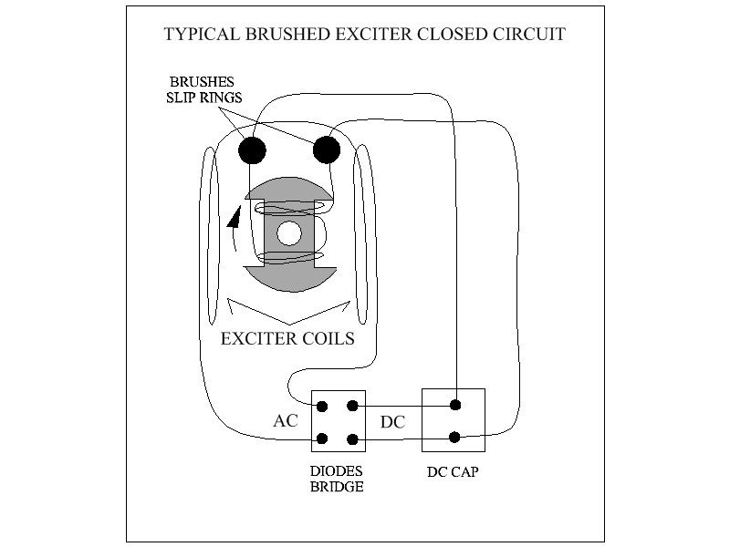 [/IMG]
First I want to insist, that either on a Brushed or Brushless this exciting circuit is Closed at all times, and either caps type (DC for Brushed, AC Running Cap for Brushless) keep a minimal charge, even when not in operation, plus there is a magnetic reminiscence at rotor core. In order that whenever we start spinning the rotor, current starts flowing and a stronger magnetic field is built through Rotation.
Then, as Rotor reaches required operating RPM's, output power would be at Mains...simple deal.
Now, if we look at Rotor Field Winding is based on fine gauge and many turns, configuring two coils in series, which basically generate just one magnetic field at iron core.
In the case of the Gen I would be working on Rotor Field Coil(s) in series are 67 Ohms, measured right at the two rotor slip rings, before going to brushes.
And Both Exciting Coils at Stator measured exactly 1.4 ohms measured before going to rectifier diodes.
The DC Electrolytic Cap is 200V, 270uF, which means it is only a "momentary low storage" cap.
The difference from both windings is huge...which means that in order to satisfy that Rotor Field Coil to produce the strong enough field, it must spin at the required 3600 RPM's.
This is a self maintained closed circuit, where the Stator Exciting coils induced by the magnetic field at rotor, retro feeds the supply at rotor coil via diodes-cap in order to maintain a closed cycle at all times.
In other words, this exchange "network", must be in a perfect balance in order to perform properly.
That is why my insistence on having exactly the same resistance, as the same number of turns, the same gauge, the same coil pitch, etc,etc at the energized groups of coils at the static armature.
Once we get this system to be balanced and self maintained...it is just a matter of spinning field to RPM's and watch output go up and up...Rock and Roll time!
Regards to All
Ufopolitics
Hello Cadman and All,
Below I drew a black and white, plain circuit of a typical brushed generator type:
[IMG]
 [/IMG]
First I want to insist, that either on a Brushed or Brushless this exciting circuit is Closed at all times, and either caps type (DC for Brushed, AC Running Cap for Brushless) keep a minimal charge, even when not in operation, plus there is a magnetic reminiscence at rotor core. In order that whenever we start spinning the rotor, current starts flowing and a stronger magnetic field is built through Rotation.
Then, as Rotor reaches required operating RPM's, output power would be at Mains...simple deal.
Now, if we look at Rotor Field Winding is based on fine gauge and many turns, configuring two coils in series, which basically generate just one magnetic field at iron core.
In the case of the Gen I would be working on Rotor Field Coil(s) in series are 67 Ohms, measured right at the two rotor slip rings, before going to brushes.
And Both Exciting Coils at Stator measured exactly 1.4 ohms measured before going to rectifier diodes.
The DC Electrolytic Cap is 200V, 270uF, which means it is only a "momentary low storage" cap.
The difference from both windings is huge...which means that in order to satisfy that Rotor Field Coil to produce the strong enough field, it must spin at the required 3600 RPM's.
This is a self maintained closed circuit, where the Stator Exciting coils induced by the magnetic field at rotor, retro feeds the supply at rotor coil via diodes-cap in order to maintain a closed cycle at all times.
In other words, this exchange "network", must be in a perfect balance in order to perform properly.
That is why my insistence on having exactly the same resistance, as the same number of turns, the same gauge, the same coil pitch, etc,etc at the energized groups of coils at the static armature.
Once we get this system to be balanced and self maintained...it is just a matter of spinning field to RPM's and watch output go up and up...Rock and Roll time!
Regards to All
Ufopolitics


Comment