Very Nice U.P. I wish I could draw like that. It makes things so much simpler to get the point across. @Stealth, nice find on those neos.
What a great project!
Happy Building,
Randy
Originally posted by Ufopolitics
View Post
Hello to All,
First please allow me to write this part "in general" speaking...
@Cornboy: Hey Old Friend!!...is grrrreat to see you here!!...I know you are a heck of a builder, and would be able to thrust this design all the way into the world. So a very warm welcome to you.
@Mack: Thanks for all your disclosure here...It is enough for Us to build the whole thing with what you have very patiently shared...Anyone with Motoring Skills and Electromagnetism knowledge can be able to make this a reality...I believe we all have more than enough to make it happen...and it would be only our limitations the ones keeping from not achieving this very exciting project.
Thanks again...and please, don't take any crap from anyone, your knowledge is all yours...it is gained through years of experience plus your capability to go straight forward...and wish one day we would meet again.
@BroMikey: Yes there are always gonna be the attacks everywhere we go trying to make a demonstration that Free Energy, Motion Perpetual and the works exists...no matter what the old physics concepts has tried so hard to encapsulate within our brains...there are ALWAYS going to be guys like Us all around...The "Divergents"... that don't accept whatever crap they have shown trying to inculcate/stamp in our heads ...and have done it no matter for how many hundred years...we will be here friend to defeat them all...always!
Now, related to "Technicalities" and the way I see them...
THE WRONG ROTATION SENSE
There was a post from MadMack that I just cited a fragment below containing the very essence from it, and it refers to a graphic (which I added below as well) that you've displayed before, BroMikey:
Mack's insistence above... for you and of course...for All of Us building this motor, to test both possibilities, by flipping rotor is VERY obvious...and strong.
If you look at my settings in all my CAD's is the same as yours...well, it is the VERY WRONG WAY friend!
I have conducted tests in both ways, since I made my rotor that could be reversed...and let me just say this....We were (and whoever else that was ONLY trying this way, as your graphic above) attempting to start a gas engine with the distributor mounted at 180� OFF from Compression TDC....it will NEVER start if we are sending the spark at the Exhaust Stage Timming...and not at compression cycle.
The "Power Stroke" is so clear it will jump in front of your eyes...when we do the right placement of rotor/magnets angles...
I have been writing this post approximately for three hours (including making the CAD below)...just because I consider that we all have ALL the tools required to make this Motor work...is only up to Us to make it happen...on my end, I will try my best to guide anyone who is replicating it...and showing his/her failures or negative issues graphically by whatever means, while I build mine. And I am NOT saying it is simple...we are playing with INVISIBLE FORCES at all times...and our interpretation could render right or wrong results...only severe and repetitive testing with as many different options available will give us the right paths...
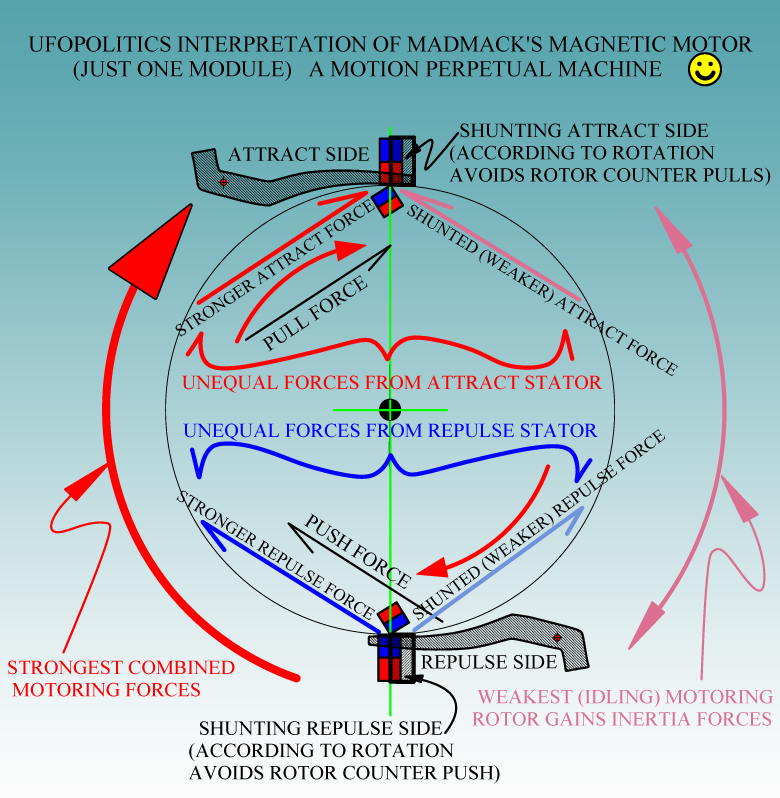
The CAD above kind of summarizes all the disclosed material by Mack, including the latest shunting the stators...and only assuming that Repulsion Ramps are identical to Attract Ramps...since He did not refer to any different specifications previously...except to use the back poles from stators as an Option that we should decide if or not to follow...
Any Motor have an Idling Stage-Side (a gain of inertia with weakest or no forces applied,(turned off energy to coils for the case of rotor coils)...some have it very narrow timing...and some wider angles and longer times...As also a Strong side where the attract-repulse forces are executed with the presence of rotor magnets or coils.
The "Modular" repetition generates the continuity of rotation at the right angles distribution, in order to complete the 360� for full-constant rotation.
In the case of this Magnetic Motor, we should consider to space Modules properly, in order NOT to interfere/overlap interactions for each rotor magnet-stator-ramp module with the adjacent ones, which could bring undesired results.
Even though we all have Mack's recommendations of which system (number of modules plus angles apart) has worked for him...
I will now get back to work on this beautiful Machine...
Regards to All
Ufopolitics
EDIT 1: @BroMikey and anyone who Mack has called/cited his/her posts: Please, DO NOT re edit them as it would change the thread learning direction when a newcomer starts reading...for example you Mikey...You have changed post #61...by re editing text...plus you took off the image that Mack was calling/citing for wrong rotation sense...Don't do it, please!...I am glad I found image in the previous page...I have been reading those two posts for a while...so I noticed the change.

 I wouldn't doubt it. I


 it worked in 1918


Leave a comment: