Announcement

Collapse
No announcement yet.

William F. Skinner - 1939 Gravity Power

Collapse
X
 
  • Filter
  • Time
  • Show
Clear All
new posts

  • I hope I am not boring everyone. to bad.

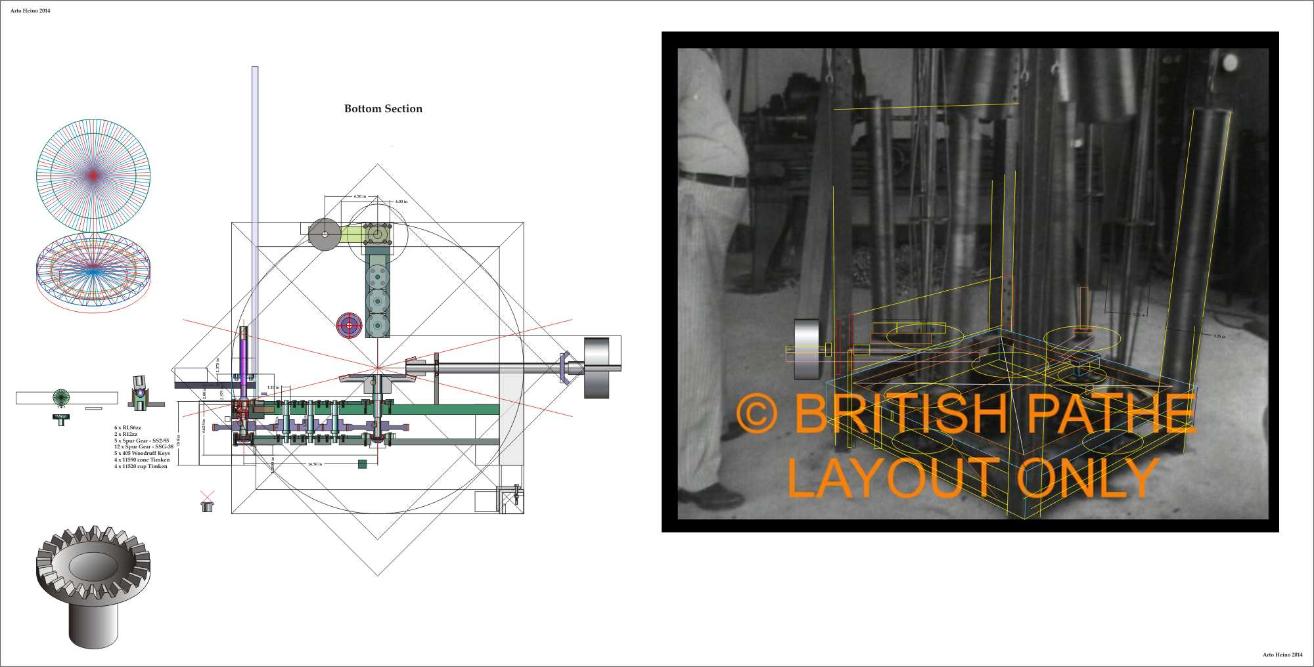
    This shows more than the video did on how David John

    did some of his Skinner work as different as it may seem.


    Comment


    • Comment


      • Here is the last of what David Johns 38 year quest is showing

        in picture form. Skinner did it different both wobble taking

        advantage of gravity. As a beginner this stuff is easier to grasp

        for me and since David John started 38 years ago maybe he

        wised up trying not to show all of the complicated designs

        first. At least not to the average person.

        We could learn a thing or two from this guy and throw out

        what we don't like


        Last edited by BroMikey; 06-07-2015, 04:07 AM.

        Comment


        • has to load the output

          Where is the free fall in the machine? The shaft that the weights are connected to rotate in a fixed position... I know the shaft is rotating on its own axis while rotating around the cycloid gear (don't recall the name for that), but the weights are at a fixed height - the shaft does not slide up and down.

          The weights are not moving independently of the shaft it is on since they are screwed on to it with plumbing pieces - so since the shaft is at a fixed height, so are the weights.

          Moving the weight in and of itself is not proof of work being done. Yes, force x distance = work but the same thing applies to the Bedini SG.

          The wheel turns, we have said from the beginning add that work to the electrical recovery and it is over 1.0 COP. It can be more but this is the basic. When we talk about the mechanical work being done, we're not talking about the free spinning wheel with no load attached to the shaft. The reason we know how much work is being done is because we have attached a wheel to the shaft and loaded it with friction from a leather strap and each end of the strap is hooked to a spring loaded scale. The work we quote is from actually calculating THAT work done by overcoming the friction of the leather shaft and in the attraction mode, it has shown to be up to 30% of the electrical equivelant. So if there is 0.9 cop on a good build, adding the work of the wheel is a cop of 1.2 cop for example. When loading it up, the input and output changes, but they stay fairly proportional to each other and we can still see the input compared to recovery under load. That is where the claims came from, not just making something up about how much mechanical work is being done because the wheel is free spinning with no load attached. Of course it is not designed for much mechanical work since the wheel is a switch, but the point is, the mechanical work has to be calculated with a load.

          With this other machine, that work claim is invalid because the claim needs to be based on giving the rotating weights/shaft assembly a load and seeing what work is there and then seeing what the input is and then compare. With that machine, I would predict that any real load on the shaft will cause the input motor to catch on fire since it is a conventional motor and the current will increase.

          He needs to do this:

          [VIDEO]https://www.youtube.com/watch?v=Zox7EnafQmE[/VIDEO]

          Also, as soon as you attach a real load to it, it is instantly reflected back to the input motor and the motor will burn up. That is because the output is directly proportional to the input with losses. This in and of itself is evidence (and the weights being at a fixed height) that the machine is a closed loop system with no ability to utilize and put free gravitational potential (or other free environmental input) to work. The principles of simple closed systems apply - there is absolutely nothing in its mechanism to regauge itself to a new potential difference in any way to allow a periodic input of occasional free input from anywhere.


          Originally posted by BroMikey View Post
          Here is a comment

          gconol 6 months ago
          Patent pending my ass .... this is william Skinner's idea. Stop stealing other people's work.


          Oh yeah Aaron I know what i was going to say now.

          When JOHN did the 4 video's he showed how only .5 watts-1 watt

          was needed to move all of those weights in a wobbling fashion.

          I thought it significant that with 4X the weights added that

          under 1 watt was needed to move that much mass.

          If I hooked a scooter motor up to that much weight traveling

          in a circle it would cost me far more than 1 watt. Wouldn't

          you agree with that simple assessment?

          Sure JOHN is way off on the idea but shouldn't it cost more

          than 1 watt?
          Sincerely,
          Aaron Murakami

          Books & Videos https://emediapress.com
          Conference http://energyscienceconference.com
          RPX & MWO http://vril.io

          Comment


          • elliptical orbit

            That's fine if that is what you want to believe.

            That wheel is irrelevant to the point that the crossbar is obviously moving and at the end of the crossbar, there are the little "cam" or swingarms that rotate independently of the oscillating crossbar and the top of the shaft is moved in an elliptical orbit.

            We can agree to disagree and I don't think there is much more either of us can add to this particular segment of the Skinner machine that can emphasize our beliefs on it any more than we already have.

            I'm open to you proving me wrong with a build that moves the shaft in the circular orbit.

            Originally posted by MagnaMoRo View Post
            Hello Aaron,

            This is what I see:
            Sincerely,
            Aaron Murakami

            Books & Videos https://emediapress.com
            Conference http://energyscienceconference.com
            RPX & MWO http://vril.io

            Comment


            • Okay now I follow you. Even though it is a little to much

              for me to chew on, I see that a load is needed on the other

              John device. Now I am looking at this one of yours again

              and it seems so much different to me after the other video.

              Thanks Aaron.

              https://www.youtube.com/watch?v=JolNozy8UEY

              Comment


              • elliptical orbit

                Even if the input lever is moving in a strict linear motion, the lower shaft is still moved in an elliptical orbit. With the input lever moving in an elliptical motion, we're compounding these advantages even more.

                Originally posted by BroMikey View Post
                Okay now I follow you. Even though it is a little to much

                for me to chew on, I see that a load is needed on the other

                John device. Now I am looking at this one of yours again

                and it seems so much different to me after the other video.

                Thanks Aaron.

                https://www.youtube.com/watch?v=JolNozy8UEY
                Sincerely,
                Aaron Murakami

                Books & Videos https://emediapress.com
                Conference http://energyscienceconference.com
                RPX & MWO http://vril.io

                Comment


                • To MagnaMoRo, In your post #604 you linked the video I put up , but you also put that blow-up beside it. How do you do this? I would like to try to clean it up some but can't seem to save it in motion only still.

                  To Aaron, Did you watch the video from post 604 and MoRos' blow-up?
                  The front crossbar is above the cam when the cam rotates ,as it passes the crossbar, because of the poor quality video, to me it is giving the illusion of the crossbar moving. Look to the left you can see the crossbar (barely) ,but it doesn't move.
                  Do you see this?
                  Maybe the best is to build it both ways and test.
                  artv

                  Comment


                  • Originally posted by shylo View Post
                    To MagnaMoRo, In your post #604 you linked the video I put up , but you also put that blow-up beside it. How do you do this? I would like to try to clean it up some but can't seem to save it in motion only still.
                    Hi shylo,

                    If you go back to that post and press the QUOTE button as if you where going to respond to my post, you will be able to see the code generated for the response wherein you can edit your message. Study the code and you will understand how to place things side by side; don't use a space or return between the linked pictures and/or videos. Once you create your response just be sure to preview it to make sure it looks the way you expect. You can edit and preview as often as you need to before final posting.

                    Animated .gif files are built up in layers and will only display as animations in a web-browser or perhaps in some other specially designed software, otherwise usually only the first layer will show. I believe that if you try to copy-and-past from an animated .gif it will only copy the first layer. To get the hole animated .gif over to your computer you have to actually download the .gif file by using "Save Image As" from the Right Mouse Click menu.

                    I hope that helps.
                    MagnaMoRo

                    Comment


                    • the crossbar moves

                      Originally posted by shylo View Post
                      To MagnaMoRo, In your post #604 you linked the video I put up , but you also put that blow-up beside it. How do you do this? I would like to try to clean it up some but can't seem to save it in motion only still.

                      To Aaron, Did you watch the video from post 604 and MoRos' blow-up?
                      The front crossbar is above the cam when the cam rotates ,as it passes the crossbar, because of the poor quality video, to me it is giving the illusion of the crossbar moving. Look to the left you can see the crossbar (barely) ,but it doesn't move.
                      Do you see this?
                      Maybe the best is to build it both ways and test.
                      artv
                      I can zoom in all the way and see that the pixels are moving - it isn't an illusion. Even zoomed out, it is apparent. I show that in the short video clip I posted. The crossbar is moving.
                      Sincerely,
                      Aaron Murakami

                      Books & Videos https://emediapress.com
                      Conference http://energyscienceconference.com
                      RPX & MWO http://vril.io

                      Comment


                      • Hi Aaron, Can the pixals differentiate between the stationary crossbar, and the rotating cam ,when they cross paths?
                        That white streak you see ,is the trailing edge of the cam ,as it rotates clockwise , looking down from the top...
                        The white streak appears, just as the cam is going to the inside of the structure passing under the crossbar frame work that holds the drive for the cams.
                        The cams are connected to the pulley or gear that is rotating in a circular path.
                        The rod that travels down to the gimble and translation plate moves in a circular path.
                        The rod terminates in the plate, The upper weight is attached to that plate, The lower rod is attached to that plate, With lower and upper rods attached to the plate makes it sit off level.
                        With the plate off level , one side is high, one side is low, The upper weight fits in there somewhere, along with the lower.
                        I think you get gain for about a quarter the rotation.
                        artv

                        Comment


                        • the crossbar is moving

                          Originally posted by shylo View Post
                          Hi Aaron, Can the pixals differentiate between the stationary crossbar, and the rotating cam ,when they cross paths?
                          That white streak you see ,is the trailing edge of the cam ,as it rotates clockwise , looking down from the top...
                          The white streak appears, just as the cam is going to the inside of the structure passing under the crossbar frame work that holds the drive for the cams.
                          The cams are connected to the pulley or gear that is rotating in a circular path.
                          The rod that travels down to the gimble and translation plate moves in a circular path.
                          The rod terminates in the plate, The upper weight is attached to that plate, The lower rod is attached to that plate, With lower and upper rods attached to the plate makes it sit off level.
                          With the plate off level , one side is high, one side is low, The upper weight fits in there somewhere, along with the lower.
                          I think you get gain for about a quarter the rotation.
                          artv
                          The distinction between the crossbar and cams are clear as day in both the zoomed out higher quality view and the lower quality zoomed in view where it is very pixelated.

                          Yes, the white streak is the cam rotating - while the axis of the cam is oscillating back and forth on the end of the crossbar.

                          Video evidence shows a clear distinction between the crossbar and cam and that BOTH are moving, I respectfully disagree with the rest of your assessment that the cams are rotated by a pulley.
                          Sincerely,
                          Aaron Murakami

                          Books & Videos https://emediapress.com
                          Conference http://energyscienceconference.com
                          RPX & MWO http://vril.io

                          Comment


                          • Preliminary Drawings

                            Hi All,
                            Here are some of my last Skinner studies with my interpreted drawings, not finalized just preliminary layouts before actual build material and cost assessment. These should help some of those who have questions about some of the details. The top section is still incomplete in these drawings, the lower section with the arm and spinning weights have not been included.

                            I hope these partly finished detailed drawing can help other builders, regards Arto


                            Comment


                            • Artoj, If you look at post #610, it shows the bottom drive more clear.
                              If you remove the weights and the shafts, but not the cam, flip it over and attach the upper shafts to where the weights were attached , you now have the upper drive.
                              I think if you did have that crossbar (which is quite visible ) in the lower drive,swinging back and forth,
                              You would tear the machine apart.
                              Just my opinion.artv

                              Comment


                              • Great input abounds.

                                Nice studies you have done here.


                                Last edited by h2ocommuter; 06-21-2015, 06:48 AM. Reason: Mute question.

                                Comment

                                Working...
                                X