 Tweet
Tweet
I think the Murakami E.D. will work better than the idea of a horizontal
bar that oscillates back and forth on a pivot with another short bar that pivots on it's end and "whips" around as Aaron laid out in one of the videos
with the white graph paper pieces.
I built a crude version of the horizontal arm type and the short bar wouldn't
always whip around as the longer bar was oscillated back and forth. Often it
would just remain basically at right angles to the longer horizontal bar.
Keep in mind that we have to coordinate the rotating upper weights with each other in order to keep the forces balanced. Any given upper weight
has to move in a manner exactly opposite to the one across from it on the machine or the whole thing will vibrate itself apart or across the floor.
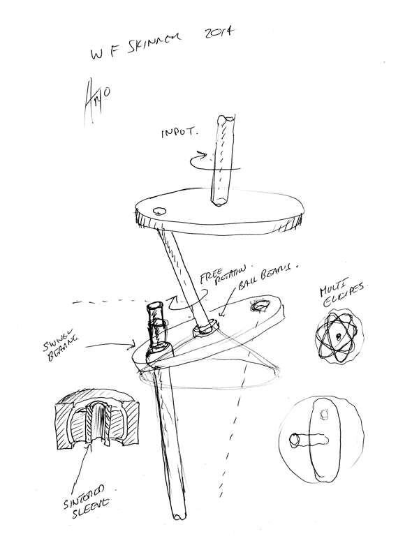
I'm still not convinced that we need to move the lower end of the input lever shaft in an ellipse. Maybe the question to ask is what motion would serve us best?
It seems to me the top of the bottom weight shaft (where it attaches to the translation coupler in a spherical bearing) moves in a circle through volumetric space (through the air). To try to confine it to an ellipse would
require significant force that would always be fighting the centrifugal force
of the lower, tall weight. That would lower the output of the whole machine.
Therefore if the top of the bottom shaft moves in a circle, the translation coupler must move in a circle which means the bottom of the input lever rod
must move in a circle. That means the top of the input lever rod must move in a circle. ?
Trying to visualise it all is fun.... I think the lower weight's shaft lower pivot/bearing point (just above the gear but below the universal joint), and the x/y pivot point in the frame of the input lever rod must be lined up vertically so both the upper and lower weights are moving in circles in the air.
The lower tip of the input lever rod and the upper end of the lower shaft would be drawing circles in the air but they would be different diameters.
The translation plate would be doing some sort of dance around these 2
pivot points.
watching the videos it seems that my eyes and brain can see whatever motion of the top end of the input lever rod I want to see. I can see it moving in a clockwise circle. then if I play it again I can see it turning in a counter clockwise circle. then if played again I can see it oscillating back and forth. ???
the above are just some musings on the workings of it all.
I could be completely wrong.
I sure am enjoying this discussion forum, thanks for almost everyone's helpful and insightful input.
You bet this is getting exciting!
Tom
bar that oscillates back and forth on a pivot with another short bar that pivots on it's end and "whips" around as Aaron laid out in one of the videos
with the white graph paper pieces.
I built a crude version of the horizontal arm type and the short bar wouldn't
always whip around as the longer bar was oscillated back and forth. Often it
would just remain basically at right angles to the longer horizontal bar.
Keep in mind that we have to coordinate the rotating upper weights with each other in order to keep the forces balanced. Any given upper weight
has to move in a manner exactly opposite to the one across from it on the machine or the whole thing will vibrate itself apart or across the floor.
I'm still not convinced that we need to move the lower end of the input lever shaft in an ellipse. Maybe the question to ask is what motion would serve us best?
It seems to me the top of the bottom weight shaft (where it attaches to the translation coupler in a spherical bearing) moves in a circle through volumetric space (through the air). To try to confine it to an ellipse would
require significant force that would always be fighting the centrifugal force
of the lower, tall weight. That would lower the output of the whole machine.
Therefore if the top of the bottom shaft moves in a circle, the translation coupler must move in a circle which means the bottom of the input lever rod
must move in a circle. That means the top of the input lever rod must move in a circle. ?
Trying to visualise it all is fun.... I think the lower weight's shaft lower pivot/bearing point (just above the gear but below the universal joint), and the x/y pivot point in the frame of the input lever rod must be lined up vertically so both the upper and lower weights are moving in circles in the air.
The lower tip of the input lever rod and the upper end of the lower shaft would be drawing circles in the air but they would be different diameters.
The translation plate would be doing some sort of dance around these 2
pivot points.
watching the videos it seems that my eyes and brain can see whatever motion of the top end of the input lever rod I want to see. I can see it moving in a clockwise circle. then if I play it again I can see it turning in a counter clockwise circle. then if played again I can see it oscillating back and forth. ???
the above are just some musings on the workings of it all.
I could be completely wrong.
I sure am enjoying this discussion forum, thanks for almost everyone's helpful and insightful input.
You bet this is getting exciting!
Tom

Comment