Announcement

Collapse
No announcement yet.

Mr Lester J Hendershot's magnetic generator.

Collapse
X
 
  • Filter
  • Time
  • Show
Clear All
new posts

  • Originally posted by GSM View Post
    I am indebted to 'Crusty' who forwarded this file link today. Thank You Crusty.

    http://www.overunity.de/downloads/sa/downfile/id/14/

    Check out the C1 long foil tabs emerging from the bottom of both coils !

    Is this the foil which collects internally radiated charge and maintains oscillation ? Thus being both an essential input trigger terminal, as well as for observing feedback via a HiZ scope probe ?

    See Crusty's own circuit drawing which he traced from the photos of this Aho generator, that might have been a self runner, if only temporary.

    Is that a radio or amplifier to the right of the main board, used to listen for oscillation start-up and tuning ?
    An AM radio is something I have used in the past to show whether an audio amplifier output stage is momentarily 'squegging' reactively on transients.

    Good to see your links too Morpher. I studied your Hendershot vids back in 2009-10, and yes there is much to consider in relation to Lester's NOT simplistic buzzers.

    Cheers ............ Graham.
    Hello GSM,
    clarence here,

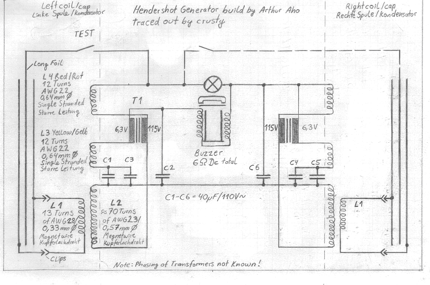
    Do you possibly know how I might get a translation in english of the AHO document in the link you show. would definitely appreciate your time and consideration concerning this. I have salvaged the two ring magnets from an old microwave magnetron and as soon as I obtain the capacitors I plan on building it. thanks much Sir! mike, onward!

    PS: I believe the reason for the corrosion Hendershot experienced in the coffe can liner was due to galvanic dissimilar metals corrosion which I was familiar with in the military working with aluminium frame components and various different metals being attached. we simply used an appropriate dissimilar metals tape between surfaces. Im sure your probably familar with that however. to bad Lester didnt get to do the same.
    Last edited by clarence; 12-10-2012, 02:19 PM.

    Comment


    • Rough Translation

      Hi

      Here is a rough translation of the above doc:

      Hendershot in Farbe-translated.docx -- 3.9 meg

      Regards

      John

      Comment


      • Originally posted by john_g View Post
        Hi

        Here is a rough translation of the above doc:

        Hendershot in Farbe-translated.docx -- 3.9 meg

        Regards

        John
        Can't download anymore - it's setup so anything over 50 Megs (about 13 downloads) exceeds the limit allowed at that site. Could someone upload it elsewhere? I think sendspace.com is easy, no sign up needed and may allow more downloads.
        There is no important work, there are only a series of moments to demonstrate your mastery and impeccability. Quote from Almine

        Comment


        • Originally posted by john_g View Post
          Hi

          Here is a rough translation of the above doc:

          Hendershot in Farbe-translated.docx -- 3.9 meg

          Regards

          John
          clarence here,

          tried to upload but it said to wait until later! thanks anyway , mike, onward!

          Comment


          • Thanks Ewizard

            Originally posted by clarence View Post
            clarence here,

            tried to upload but it said to wait until later! thanks anyway , mike, onward!
            @Ewizard

            Thank for tip re sendspace:

            Download Hendershot in Farbe-translated.docx from Sendspace.com - send big files the easy way

            Regards

            John

            Comment


            • Generator built to specifications by way of Lester Hendershot Aho.

              Should, according to the current owner during the commissioning
              Lester Hendershot have brought a 60 watt bulb to light up

              This version will be known to you safely from the Internet:

              In the footer of this brochure in the background is my opinion, "By Arthur C. Aho".

              Here one sees the buzzer.

              Both electromagnets are similar from a bell expanded and the metal strip in which the two electromagnets are secured (at the side where the connector contacts), fixed to the piece of Plexiglas and slidably connected to the spindle to the magnet / sheet metal strip.
              This can be seen on the last picture in this document one more time.
              The DC resistance of the two coils in series is 6 ohms.
              The magnet is 5 inches wide, 1.5 inches deep, and 1 inch high.
              The metal strip is 5 inches wide and 1 inch high.
              The external dimensions of the electromagnet are: 2.5 inch length at 1 inch diameter.
              The diameter of the enamelled copper wire is about 0.51 mm or about AWG 24

              From a report by Skilling I learned that the buzzer is the interior of a larger built headphone speaker. I can not quite understand that on a magnetic speakers (see diagram), which in my opinion, this arrangement comes During the next wound coils on the costs associated with the magnetic poles of iron bars. Then when a voltage is generated at the coil magnetic field would be superimposed on the magnetic field of the permanent magnet and thereby modulate the magnetic flux through the iron rods and the iron membrane. The air gap between the iron rods and the membrane can be adjusted in such headphones via a thread. That lasts again a similarity to the buzzer.

              Ma = magnet, S = coil, Me = iron membrane
              Furthermore shows Skilling, Hendershot had used during his early attempts headphones and when he heard a scratching noise "scratching sound", this was the sign that the generator is now in operation and was unable to give a performance.
              In the development and increased capacity of the generator has run this "Loud Speaker" larger dimensions and a part of the generator.

              This is the "left" PCU.
              I had always wondered what else should be that TEST "point".
              This detail photo and the diagram (see below) it is clear

              The coil is wound flat on the bottom section of the wire coil is, look at the two "+ contacts" of the former duo TM58 - "clipped" electrolytic capacitors.

              This is the wire coil of the "right" PCU. Again, the ground pin of the former duo TM58 Elko's is brought out. He was pushed to the test directly to the terminal contact of the lamp base. I have it shown by dotted lines in the diagram

              View of the transformer / transformer in the "left" PCU.
              It is an American 110V to 6.3 V power transformer.
              The metal used in this version of the PCU's rings are made of cold rolled mild steel and thus are magnetic. They are spot-welded at the seam multiply / overlap point. The inner diameter of the metal rings is 5.25 inches, and a height of 2.75 inches.

              The circuit reminds me rather of the information published by Skilling and O'Brian diagrams. What is new is the presentation of lampwork capacitors in the PCU's. The mass foils us connections of the former Pyramids TM58 Duo electrolytics I have with drawn because they are used in this circuit.

              All unmodified capacitors have a capacitance of 40μF at 110V AC.

              I have canceled the pictures because I'm not in the mood to create the basis for lau any item in any "free energy" Newspapers / Manuals.
              To replace the devalued against not good, I have seen images / movies etc. regarding this topic, I'm ready.
              If interested please crusty7@gmx.de
              Half of the Answer is knowing the right Question

              Comment


              • Half of the Answer is knowing the right Question

                Comment


                • Originally posted by Dave45 View Post
                  The metal used in this version of the PCU's rings are made of cold rolled mild steel and thus are magnetic. They are spot-welded at the seam multiply / overlap point. The inner diameter of the metal rings is 5.25 inches, and a height of 2.75 inches.
                  Strikes me that the only thing different in this description when compared to Hendershot's original working devices relates to the metal being used.
                  The original cores were cut from good old fashioned 1940-50's tin cans.
                  They don't make them like this any more, yet originals are still available on e-bay as collectors pieces;-

                  Vintage Maxwell House Drip Grind Coffee Tin Can Lid 1lb Advertising Lithio 2 | eBay

                  Note: A 40uF capacitor on both sides of the buzzer does not make sense.

                  Cheers ........... Graham.
                  Last edited by GSM; 12-10-2012, 10:31 PM.

                  Comment


                  • The Hendershot Mystery(98)140pp
                    Half of the Answer is knowing the right Question

                    Comment


                    • Originally posted by Dave45 View Post
                      Please Dave, what is it you wish us to consider ?

                      Have you read all of this thread to date, for so much has already been covered ?

                      Cheers .......... Graham.

                      Comment


                      • Im sorry if its already been posted I ran across this site and posted it.

                        Did Hendershot invent the alternator we use today, but his self ran? very interesting.

                        What would happen if we connected the sandwiched coil to a cap and arranged permenant magnets around the perimeter of the claws, or just a horseshoe magnet as Hendershot seemed to favor.
                        Changing the capacity would change the frequency that the claws flipped their poles.

                        Just some thoughts, wondering how he got this arrangement to self run.
                        Half of the Answer is knowing the right Question

                        Comment


                        • Originally posted by Dave45 View Post
                          Hello Dave45,

                          clarence here,

                          just a note of thought -it is evident that there is initially a prime-mover to Hendershots devices and I dont personally belive it is the magnetic oscillator (my opinion- as all you know the worth) , however the movers in his device are: 1- coils
                          2-capacitors
                          3-cores
                          4-magnet
                          It occured to me that tesla was his mentor, and that he was supposedly knowledgeable of his inventions and patents. remembering that when studying the schematic I was thinking just why in the hell would he destroy a perfectly good capacitor and then put it back together to use it in a disrupted manner? there had to be a reason and a method to his madness. then when I saw the schematic again the picture of Teslas radient energy device came to mind! (thumbnail below) I believe he was useing the long piece of salvaged foil as his antenna plate for receiving the radient potential and at the same time useing the two short pieces of foil as a transmitter to power the initial L1 coil to consequently operate the rest of the device.

                          consider it a reversal of the normal transmitter-receiver relationship. I believe the energy in the disrupted capacitor elements would begin to amplify as the L1 coil itself would begin to alternate and definetly bring the circuits to life.

                          Just my thoughts, but all of us know some method brought these units to life!

                          PS: He also placed concern on keeping the frequency on both of the disrupted capacitors exactly the same. which was another possible use of the test points in the circuit and during normal use those points were open. If just being open all the time then what would any purpose for the disrupted capacitors be other than the KEY initial mover?

                          mike,onward!
                          Last edited by clarence; 02-09-2013, 11:29 PM.

                          Comment


                          • Originally posted by Dave45 View Post
                            Hey Clarence I noticed that too, its said he built several different versions, I think the transformers would work better in the magnetic field of the basket coils than the caps.
                            I found these caps at mouser 1000 uf capacitor Film Capacitors | Mouser Im not sure if they will work what do you guy's think they are not electrolytic they are film used in dc filtering.
                            Hello Dave45,

                            clarence,
                            I dont know about the use or nonuse of those capacitors - however I DID find some for 500v AC in both 500uf and the 1000uf values. they are made by ELECTRICON, INC- I believe in germany and they are power caps.
                            500uf 500v #E62.R17-504M10
                            1000uf 500v #E62.S24-105C20
                            you will have to find a distributor. just thought I would pass it on. LOL
                            mike, onward!

                            Comment


                            • Hey Clarence,
                              Interesting observation the cap and coil create an LC circuit on both sides and the way the cap is made it could be drawing energy.

                              If we have two LC circuits in the same circuit they must be working 180 out of phase, they are bouncing energy back and forth across the buzzer coils.

                              This is the most asymmetric system Iv ever seen, Im not sure I trust Crusty's circuit I guess a person would have to test it to find out, the buzzer coils are wound wrong for an asymmetric system.

                              Another one of my crazy drawings
                              Half of the Answer is knowing the right Question

                              Comment


                              • the amazeing hendershot

                                Originally posted by Dave45 View Post
                                Hey Clarence,
                                Interesting observation the cap and coil create an LC circuit on both sides and the way the cap is made it could be drawing energy.

                                If we have two LC circuits in the same circuit they must be working 180 out of phase, they are bouncing energy back and forth across the buzzer coils.
                                Hello Dave45,

                                clarence,
                                presuming that the remade caps are radient energy receivers for each half of the push pull and do act as the prime movers there has to be a "traffic cop" per say to allow the initial direction of voltage and current flow through each half of the circuit so that everything always flows in unison. I will say that that traffic cop is the MAGNET with its N and S poles pointing in the initial direction of flow. once that flow is initiated I believe all of the caps themselves will tend to keep the alternation in order. also the orientation of all the coils windings and the "dot" codes of the transformers themselves should be observed. you are correct I believe when you say this is a perfectly balanced system.

                                the next main item I have been considering is the "oscillation of the buzzer " and how it is effected in order to maintain the whole push pull operation frequency perfectly. there is a whole lot going on in this "junkyard invention" that doesn't first meet the eye thats for sure!

                                I am curious to know what your thoughts on the buzzer would be. love to hear them.
                                mike, onward!

                                PS: loved the drawings also!!
                                Last edited by clarence; 12-12-2012, 03:40 AM.

                                Comment

                                Working...
                                X