
Originally posted by Farmhand
View Post
-
Yeah Sputins, Beautiful pictures, any chance of the video ? A hint to search ?
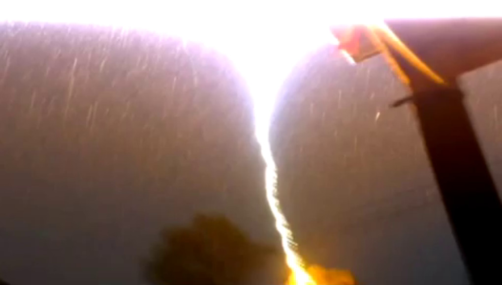
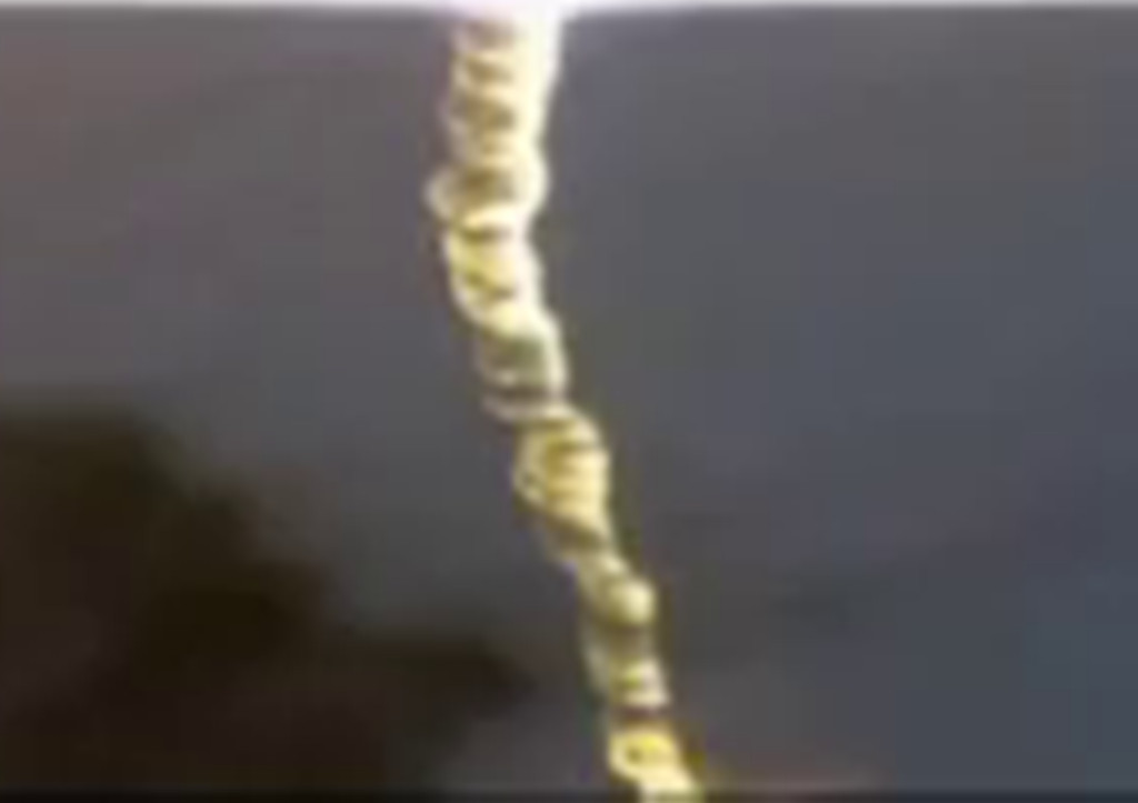
The hard conduction times make what I call "power cones", I posted a picture of
much less quality some time ago.
They look like electrical tornado's alright.
In this video of my transformer working with a rotary spark gap we can see
the hard "white" rope like conductions definitely spin up and fly apart, if the
break out point is placed near the center of the terminal I get double spirals
intertwined that can be seen to throw themselves apart after spinning up.
We can see as I vary the BPS at certain break rates there is more tendency for the white rope to continue longer.
Tesla coil test 2 - YouTube
.Leave a comment:
-
Thank you, but after reading through the website that PDF came from, I don't think I can trust it very much. The template didn't even mention any sizes, so if the DPI of my printer differs from the person who made it, they'd be tuned differently. And it didn't include the strips on backface needed to make the PCB into capacitors. With different size/materal board between the layers there'd be different capacities. Isn't it supposed to basically be an LC circuit? And what's with the overly complicated schematic for the power supply?Originally posted by orgonaut314 View PostLeave a comment:
-
This document contains a template that you can print and should give you the exact sizes. I found the site it came from pretty good.Leave a comment:
-
I would like to make one of these for a friend of mine who is sick. There are many instructional sites on making PCBs, so that shouldn't pose too much of a problem, but my biggest concern is tuning the primary coil. I understand that the other coils are log periodic following the golden ratio, but that won't mean much if the primary is out of tune, will it? What frequency should the primary coil be? (and I'd have to assume the PCB is rather uniform in its capacitance)
I should also mention that my friend has a large metal implant. Does anyone know if that or any near-by electronics would cause any complications, or do any harm to the electronics?Leave a comment:
-
What he is calling gravito Eric is posable calling dielectric. They both see a pair of waves. Interesting is that he thinks the magnetic field is carrying the gravito field. I think we would say that the electromagnetic wave comming from the magnetic antenne would have a dielectric field at right angles to the propagation of the poynting vector. So it might be spiralling around the poynting like he thinks when he constructed his wave model that was mainly an inspiration he says.
That would be a new idea for wireless transport of the electromagnetic and dielectric field? I mean we mostly work with field that have only dielectric components but normally both must be present?Leave a comment:
-
Perhaps this video inspires someone. Watch from about 19 minutes to see the inventor (Mohorn) explain his coil system that dehydrates old buildings with gravito magnetics. Meaning that he hypothesises that there is energy coming from above that he catches with a flat spiral coil almost a Tesla coil that evidently must couple electrostatic with this vertical energy. Than he polarises this wave with a normal toroid coil left or right depending on what direction he wants the water to go (rising or falling). Than he makes a sending unit that is producing a spiralling magnetic gravito wave. You have to see to understand. This whole thing is making the watter in the walls go down and makes people feel better and heals some sicknesses.
With regard to the Hendershot. The west east thing is the direction the earth gravito wave is flowing. The up down direction is the sun and other stars/planets direction. So somehow Henderson knew both frequencys to resonate both systems. The vertical should be the same as Mohorns flat coil. HTH.
The invention of Wilhelm Mohorn actually works and he got prices and it is being sold. Am I glad to find someone having succes with this new technology. Clear proven technology that works without an electric connection just on the free energy Tesla was talking about.
Have fun!
Leave a comment:
-
Hendershot Generator Resonator
Hendershot Generator:
Have put up some pictures here that covers the Generator and attempts to get it into oscillation, without success using optional 'Resonators':
Leave a comment:
-
RMR Regenerative Magnifying Receiver
Must admit that I do little circuit analysis prior to a build and wait until the device is functioning voltage wise before delving deeply into what must occur and particularly when it doesn't work first off.
Here it looks like the Grid is the modulating medium being directly connected to the CSI Primary and the regen is via L1 and the Plate.
Very much the reverse of a transmitter.
If you go back to Page 21 you will see Eric has Posted from the ARRL Handbook of 1949 (which I also have here) on Regenerative Detectors and on Superheterodyne Receivers and this is a guide to what needs to be organised.
Didn't reverse my L1 windings and need to do that but still searching for another speaker transformer.
Currently building/refurbishing the Geiger Counters.
Won four Bell Ringer Coils on Ebay yesterday for the CRD and Hendershot.
A friend dropped off a HMV 888 Vintage Radio Receiver dating back to about 1953 adding to the GLOM pile (5Y3GT/5V6GT/EBF35/6U7G/6J8G).
This Receiver also covers the Short-Wave 16.5 to 51 Metres (5.9 to 18.2 Mhz) Bands and shows how difficult it is to obtain an everyday Receiver that covers the 1600 to 3500 Khz gap where we are working.
However this can be easily modified to get down to the 1600 level as I have also bought several piles of the larger IF cans out of early vintage Receivers.
Will probably refurbish this one as it is in VG condition and just need a good working Receiver as a reference for Vacuum Tubes.
This is probably the best step for anyone interested in Vacuum Tubes is to buy an old vintage Receiver or Transceiver and refurbish it back into a working condition.
Pictures later on all of this.
SmokeyLeave a comment:
-
that circuit as shown would have the potential between the plates nearly the same. follow the leads from the 25k R, goes right to the cathode plate, the output transformer isn't going to do much with the DC.
the 100ohm makes me wonder if the 1w rating is enough as 250V thru 100ohms is roughly 625W! course the 2c22 will only handle 3.3W so that's not a big issue,not sure of the coils draw though.
I think though the bigger issue is the potentials between the plates and grid again, -10.5V for the grid.Leave a comment:
-
Regenerative Magnifying Receiver RMR
RMR Update:
Coil finished and powered up the unit but nothing in the Headphones.
2C22/7193 works well with heaters aglow and HT at 300 volts without problems.
Was unable to find a problem with the build and suspect the speaker/phone transformer to be the probable cause and looking for a replacement.
Another use for the oscilloscope to track down the problem.
Eric in his last video appeared to suggest that this was the most difficult of all and will continue until we have a resolution.
Eric is perhaps the best of instructors, gives you about 80% of what is required but you then need to fill in the missing 20% and that is how you learn.
You have many questions and don't expect an answer and you finally resolve all by answering your own questions, that's the way it should be if you want to learn.

Uploaded with ImageShack.us
2C22/7193 has an amplification factor of 20.
This is the 4th of his schematics and the last to get working and probably the most challenging as this again, has not been done before.
The large Rheostat controls the HT suggesting that there may be some voltage tuning required between the Plate and the regen coil below the Primary that was also made adjustable.
On the 'Field Intensity Meter' circuit you will notice his comment at bottom left "Note - Replace Test Oscillator with AM Radio to Receive" and this I should do as a learning step.
The other question here is the ground connection where we are receiving in the CSI setup and now in a reverse receive mode may need to be disconnected as I sense this is now a Hertzian receiver and we use the Mains ground instead - questions.
I make these Posts as a record of what I need to do and helps me to sort out the questions so I may as well Post as that is what the Master wants us to do.
Have four vintage bell ringer coils coming up on Ebay as I need one with a greater swing on the bell arm for the CRD.
Building the Geiger Counter from a Kit I have had here for some time and covers all of the Alpha, Beta and Gamma radiations.
Also bought an RBM Long 1950s unit, built here in Sydney and uses 2 x 1S5s and now have power supplies to use on this unit without the use of batteries that are no longer readily available like the 2 x 45 volt combination required for the HT of 90 volts.
Also covers Gamma Radiation.
Have Allenite and Urananite here as reference samples as I recall Reich and some of his experiments seemed to be based on insufficient reference recording and how do you discern between Cosmic Radiation (CRD) and that which is a natural degenerative Radiation that the Geiger Counter detects, other than Nuclear?
And to top that off, where does the Aether fit in with all of this and is it responsible for the natural elemental decay in radiation?
Questions!
It would be really nice if Eric could come in and explain further what the 'Cosmic Ray Detector' project was going to lead up to.
Thanks.
SmokeyLeave a comment:
-
Tesla Transformer Pulse Generator TTPG
Promised to put this up some weeks back with the notation for the -6 volts required for the Grid Bias of the 2050 Thyratron:

Uploaded with ImageShack.us
This device worked well.
SmokeyLeave a comment:
-
Oscilloscope Circle
Hello madhatter,
Good to see you are still with us.
Not going to even say I understand any of the Math but yes, most certainly does look similar.
Will always Post any scope shot that looks different and this one surely did and will attempt to trace back and see if it can't be repeated where I can take down the intimate details.
This is one of the problems of doing something outside the box as this is what you get in return but makes you want to understand the why of it all.
My view is that the probe is collecting two signals in phase as there is no side ellipse formation like you see in a Lissajou figure with varying frequency.
The probe is dangling in mid air with the little coil as pickup and could be from any of Primary/Secondary or Extra but the question is - which one?
More on this later.
Been looking at the RMR (Regenerative Magnifying Receiver) and need to place a 10 turn loop of wire around the Primary and will do this tomorrow with insulated hookup wire as being the best option so that it can be easily moved with respect to the Primary for tuning.
A lttle mystified here as to what I will hear but is the CSI working in reverse as a Receiver.
Hopefully, another first that will work for us all.
SmokeyLeave a comment:
-
Smokey, had to pop in and share some info, the screen shot on the scope of the circles and bridging looks very much like the chaotic attractor of Chua memristor oscillator. link to paper here http://www.google.com/url?sa=t&rct=j...,d.cGU&cad=rja
I've been off doing research on NDR in plasma and found some very strange results that lead me to believe they are mem-components in one simple circuit. your scope shot looks like the one predicted in the paper.
also check this The Generation, Analysis, and Circuit Implementation of a New Memristor Based Chaotic System : Figure 9Leave a comment:



Leave a comment: