Announcement

Collapse
No announcement yet.

Eric P. Dollard

Collapse
This topic is closed.
X
This is a sticky topic.
X
X
 
  • Filter
  • Time
  • Show
Clear All
new posts

  • jake
    replied
    Originally posted by David G Dawson View Post
    Adam,
    Quote:

    "Eric/David I have a transformer I am building that has an outside metal around the coil and an inside metal core in coil. Think about that, and the ratio that would exist if the outer core were attached to the inner core, and how it would effect the propagation of electricity."

    Think we may have a common 'Oscillatory Chamber' here in mind.
    Going to have to read what you have presented but getting the gist of what it is all about.
    Thankyou for your support.

    Not an easy task getting a 'something' different through to people who think they have heard it and know it all.
    Newcomers are excused as you have come here to learn and you may just have a slight inkling that 'something' new has been discovered here.

    The only way you are going to see what I am seeing is to build using my theory of 'MUltiply' and not Eric's 'Divide'.
    All the information is now also clearly displayed here as well as at 'n6kph'.

    DrGreen, my apologies and yes all 3 coils are close to 300pF and this is for Eric's Test# 1 of the Extra Coil.

    Going to try to get some full size pics organised.

    Smokey
    Smokey,

    Please don't feel as if your work is not getting any attention. Everything you have posted has been viewed and stored and helped me. You and Eric are on a different "wavelengths" and this is to be expected in a field that is as Eric put it "un-charted territory".

    It seems that you know what you are doing and if not for your coils we may not have the calculation examples that Eric has presented. It does not matter to me that you have a different opinion then Eric. It actually has helped the process because your results have lead the the previous post. I now know(kinda of, think so) what to expect and how Eric expects to achieve it. Now just because you have been unable to make the longer extra coil work does not mean it is not correct.

    You are choosing a different path. I look forward to seeing you results and what you can do with them. Like I tell my good friend who has been working on Stan Myers water fuel cell for years....

    "MAKE IT WORK, then tell me how you did it"


    In the end it comes down to what you want to achieve from all the work you are doing.

    Everyone here wants to achieve something different.

    I want to: Light a damn bulb with a copper wire, and a good ground.


    jake

    Leave a comment:


  • jake
    replied
    Originally posted by T-rex View Post
    Dr. Green Coils

    The secondary winding is the prime mover of this transformer. Here the system operating frequency is established , and then locked in place by a primary resonator. This in itself establishes a telluric transmission network, a basic resonant transformer with a mono-polar connection at the secondary neutral. Another transformer can be constructed, identical in every way except wound in an opposite direction to the first coil. Interlinking the neutrals of these two counter-wound transformers enables a one wire transmission between the two units. This is the basic telluric system. No more is needed than this.

    The extra coil is employed in order to magnify the potential to much higher values than possible with only a secondary winding*. This however involves ratios of refractions and reflection that are difficult to calculate or even understand. Hence its complications are best avoided in basic telluric resting.

    *This will increase receiving sensitivity, or "gain"

    Two modes are possible for extra coil in relation with the secondary coil. Both involve quarter wave resonant rise, this the fundamental of resonant transformation. Its also known as constant potential to constant current transformation. A constant potential is a zero impedance (short circuit) a constant current is a zero admittance (open circuit). Departure from these zero values alters the coil distribution to something other than a quarter wave.

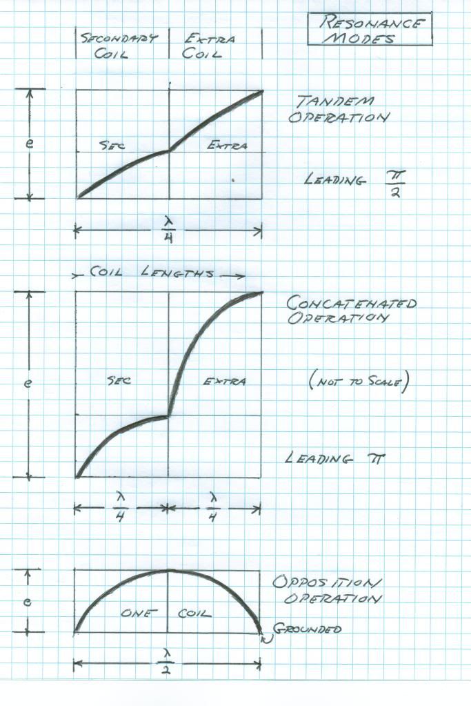
    This quarter wave can exist in a distinct pair of manifestations. The first mode is when the quarter wave is distributed over the length of both extra and secondary windings as a whole, a pair of eighth waves let us say. This is the <b>TANDEM</b> mode. A multiplication in potential is derived hereby since the extra coil exhibits a higher transmission impedance thereby giving rise to a greater EMF between turns and thus a higher termination potential. All photos of my Bolinas and Integratron setups operated in this mode. It is the easy one to achieve.

    The second mode of the extra coil and secondary coil connection involves two quarter wave distributions, one on each coil. This is not to be considered a half wave however. This mode is the <b>CONCATENATED</> connection.It compounds the quarter wave resonant rise of the secondary coil with another quarter wave rise in the extra coil, hence a concatenated resonant rise. This is the holy grail of resonant transformer design and unheard of potentials may be gained in this manner. To derive this analytically is extremely difficult, it is an advance transmission line problem. It might not even be possible to calculate or even achieve this mode of resonance, but we are going to give it a try. Tesla dreamed of this mode but electrical knowledge was in its infancy in Tesla's Colorado years. Also note that D. Dawson has become a zealot in drawing us back into the tandem mode of operation, which he claims to have mastered. It has come to pass that he is now becoming a detractor, his denouncements abound. I hereby ignore his posts and caution others that a confusion may develop here for the beginner in this un-charted territory.

    In reviewing the Dr. Green material it can be seen that this extra coil is too large, or the wire is too long. Its resonant frequency, even with the lightest coupling, is far below that of the standardizing secondary frequency.

    Extra Coil Direct: 2695 Kc/sec
    Secondary, rings: 3670 Kc/sec
    Frequency ratio: 72% lower
    Wavelength ratio: 136% longer

    Here seen is that a smaller coil is needed. However to start with, turns can be removed from the existing extra coil. But this shortens the coil, counteracting the turn removal by lowering the velocity and hence lengthening the wavelength of the coil. As a side note, both the secondary and existing extra coil should be tested independently over a wide frequency range to determine if other modes exist. All odd harmonics are resonant modes. Using the information gained from the design and construction of the existing extra coil it is possible to design and construct one for 3670 Kc/sec.

    Constructing a pair of counter wound magnification transformers and connecting their neutrals can help minimize the burden of transmission to earth, a significant distorting influence. When possible this should be done. It must be remembered that this effort is really for the experienced transmission engineer, not the HAM operator, and surely not for the beginner.

    Ignorance is blind and as my 5 year old son put it " what do you mean light moves it's just there... your turn it on and its there"...
    Yes I said you're probably right. I learned this stuff a long time ago. Now please don't call CPS..


    But Tesla was a beginner also, and through systematic experimentation made great progress with what little knowledge of standing and travelling waves in compound circuits that existed in his day. And of course he got no assistance from the pedants like Pupin. Just for fun take this problem of resonance to your local university E.E. professor, but make sure he does not see your license plate number. Is not this the way of modern society, the ones who are supposed to help are useless at best and hostile at worst? Then we have the shills?

    73 DE N6KPH
    Thank You, Thank You, Thank You


    The way you described the interactions of the secondary and primary was something I was really missing. The secondary and extra coil relations hit me like a bolt of lightning.

    Now a quick personal question.

    Does it bother you to describe these systems using the word "wave"?

    jake
    Last edited by jake; 06-27-2012, 03:29 PM.

    Leave a comment:


  • David G Dawson
    replied
    Oscillatory Chamber

    Adam,
    Quote:

    "Eric/David I have a transformer I am building that has an outside metal around the coil and an inside metal core in coil. Think about that, and the ratio that would exist if the outer core were attached to the inner core, and how it would effect the propagation of electricity."

    Think we may have a common 'Oscillatory Chamber' here in mind.
    Going to have to read what you have presented but getting the gist of what it is all about.
    Thankyou for your support.

    Not an easy task getting a 'something' different through to people who think they have heard it and know it all.
    Newcomers are excused as you have come here to learn and you may just have a slight inkling that 'something' new has been discovered here.

    The only way you are going to see what I am seeing is to build using my theory of 'MUltiply' and not Eric's 'Divide'.
    All the information is now also clearly displayed here as well as at 'n6kph'.

    DrGreen, my apologies and yes all 3 coils are close to 300pF and this is for Eric's Test# 1 of the Extra Coil.

    Going to try to get some full size pics organised.

    Smokey

    Leave a comment:


  • David G Dawson
    replied
    Secondary Tests

    Secondary Coil Tests:
    Used Primary as Test Coil with 10db Attn at Sig Gen.

    Fcarrier = 1557 Khz
    Turn 20 Fc = 1613 LSB 1530 USB 1761 Delta = 231 Hertz 231/1613 = 1/0.143211407 = 6.98
    Turn 17 Fc = 1754 LSB 1622 USB 1850 Delta = 228 Hertz 228/1754 = 1/1.129988597 = 7.69

    Now, of course, I do not understand what that number is telling me using your calculation.

    Note at bottom says to replace Sig Gen with AM Radio.
    Did so but used pickup head with Headphones.
    ALL metal gave local AM Radio Station signal but was loudest at level 5 at top hat condenser down to ring coil.
    Level 5.5 at Turn 17.

    It occurred to me to extend top hat upwards with following results with Sig Gen attn at 20db:
    The risers were 4x4" blocks of Jarrah hardwood 290 mm long.
    290mm above ring coil = 5uA (30uA)
    290mm + 290 = 10uA (60uA)
    290 + 290 + 290 = 14.5 uA (85uA)
    Brackets were first effort and an estimate.
    Criteria here was to place my hand near the top hat can and if I received an increase in signal then I needed more height.
    Total height was about 1 meter where no change in signal level was noted.
    Even a small nail I had out the side of two of the blocks I was able to just hear the Station at about level 0.5.
    So the bulk of signal here was all TEM (contact).

    It then occurred to me to try the probe head looking for a LMD (no contact) signal and was able to hear at level 1 directly under the Copper ring coil.
    All metal above this ring level at 0.5, weak but readable.
    So LMD component was there but weak.

    Not going to agree with you that the Secondary is the Telluric magnifier here as my method clearly displays a 'something' else.
    I see the Extra Coil as being a container of LMD energy just like a capacitor stores charge but we may like to call this an Inductive capacitor which only recognises or holds a LMD style energy or charge like as in a 'square' box.
    So now if you had two of these intertwined in two axes so that you did form a 'square' box you would have an infinite power plant and that is now worthy of experiment as it begins to match Dr Jan Pajak's 'Oscillatory Chamber'.
    Quote:
    "And more than that, Tesla's "extra coil" - quarter-wave resonator which HOLDS the energy (it presents anthena that doesn't emit), and (if the spiral coil is properly adjusted) through the relation of voltage standing wave, it enables huge INCREASE of voltage" etc.
    This from the Beograd people and I totally agree.

    I am attempting here to show you what you have all missed out on - that 'something'.

    Smokey

    Leave a comment:


  • David G Dawson
    replied
    Crystal Set Initiative

    John,
    Quote:
    "Any chance you could show a diagram of connections/schematic, response curves, and coil dimensions?"

    It's all there but will clarify here:
    The Extra Coil test is Eric's 1st Test and only difference is that the meter is connected directly to the end of the Extra coil and not via a pick-up head.
    I got what I expected from my coils but not from Erics.

    Primary:
    Fcarrier = 1557 Khz
    Diameter 488mm
    90mm x 3100mmx 0.7mm Copper sheet.
    Integrated capacitor of 1200pF.

    Secondary:
    Diameter 488mm
    One turn = 1533mm
    20 Turns = 30700mm
    awg 14

    Extra:
    Diameter = 195.2mm
    One Turn =613.2mm
    30700/613.2 = 50.1 Turns
    awg 14

    Best pick-up distance from Extra coil = 20" using 1N34 FWBR probe head to Headphones.

    New Extra will be using 20awg still of 50 turns as I feel Surface Area is more significant than Copper Mass.
    Thanks.

    Smokey

    Leave a comment:


  • IndianaBoys
    replied
    &quot;X Antenna&quot;

    Eric,

    Checking with you to see if you remember this?

    There is an antenna I came across searching 5 years ago called the "X Antenna". I had pulled it down as a file but with loss of a hard drive over the years and repeatedly looking thorough all the files i have, I have not been able to locate it and thought it may be appropriate on this thread to describe it and maybe someone would know of it or have access to search information related to this antenna as I can only assume it has been scrubbed from the net.

    Two brothers that were repairmen for commercial radio stations.
    They would go out and repair radio antennas and equipment.
    They came up with an antenna they called the "X Antenna" as it was in the configuration of an "X".
    From what I remember, a 5,000 watt transmission would be like putting out a 50,000 watt transmission using their special "X Antenna".

    Thanks for any help locating this,

    IndianaBoys

    Leave a comment:


  • t-rex
    replied
    Dr. Green Coils

    The secondary winding is the prime mover of this transformer. Here the system operating frequency is established , and then locked in place by a primary resonator. This in itself establishes a telluric transmission network, a basic resonant transformer with a mono-polar connection at the secondary neutral. Another transformer can be constructed, identical in every way except wound in an opposite direction to the first coil. Interlinking the neutrals of these two counter-wound transformers enables a one wire transmission between the two units. This is the basic telluric system. No more is needed than this.

    The extra coil is employed in order to magnify the potential to much higher values than possible with only a secondary winding*. This however involves ratios of refractions and reflection that are difficult to calculate or even understand. Hence its complications are best avoided in basic telluric resting.

    *This will increase receiving sensitivity, or "gain"

    Two modes are possible for extra coil in relation with the secondary coil. Both involve quarter wave resonant rise, this the fundamental of resonant transformation. Its also known as constant potential to constant current transformation. A constant potential is a zero impedance (short circuit) a constant current is a zero admittance (open circuit). Departure from these zero values alters the coil distribution to something other than a quarter wave.

    This quarter wave can exist in a distinct pair of manifestations. The first mode is when the quarter wave is distributed over the length of both extra and secondary windings as a whole, a pair of eighth waves let us say. This is the <b>TANDEM</b> mode. A multiplication in potential is derived hereby since the extra coil exhibits a higher transmission impedance thereby giving rise to a greater EMF between turns and thus a higher termination potential. All photos of my Bolinas and Integratron setups operated in this mode. It is the easy one to achieve.

    The second mode of the extra coil and secondary coil connection involves two quarter wave distributions, one on each coil. This is not to be considered a half wave however. This mode is the <b>CONCATENATED</> connection.It compounds the quarter wave resonant rise of the secondary coil with another quarter wave rise in the extra coil, hence a concatenated resonant rise. This is the holy grail of resonant transformer design and unheard of potentials may be gained in this manner. To derive this analytically is extremely difficult, it is an advance transmission line problem. It might not even be possible to calculate or even achieve this mode of resonance, but we are going to give it a try. Tesla dreamed of this mode but electrical knowledge was in its infancy in Tesla's Colorado years. Also note that D. Dawson has become a zealot in drawing us back into the tandem mode of operation, which he claims to have mastered. It has come to pass that he is now becoming a detractor, his denouncements abound. I hereby ignore his posts and caution others that a confusion may develop here for the beginner in this un-charted territory.

    In reviewing the Dr. Green material it can be seen that this extra coil is too large, or the wire is too long. Its resonant frequency, even with the lightest coupling, is far below that of the standardizing secondary frequency.

    Extra Coil Direct: 2695 Kc/sec
    Secondary, rings: 3670 Kc/sec
    Frequency ratio: 72% lower
    Wavelength ratio: 136% longer

    Here seen is that a smaller coil is needed. However to start with, turns can be removed from the existing extra coil. But this shortens the coil, counteracting the turn removal by lowering the velocity and hence lengthening the wavelength of the coil. As a side note, both the secondary and existing extra coil should be tested independently over a wide frequency range to determine if other modes exist. All odd harmonics are resonant modes. Using the information gained from the design and construction of the existing extra coil it is possible to design and construct one for 3670 Kc/sec.

    Constructing a pair of counter wound magnification transformers and connecting their neutrals can help minimize the burden of transmission to earth, a significant distorting influence. When possible this should be done. It must be remembered that this effort is really for the experienced transmission engineer, not the HAM operator, and surely not for the beginner. But Tesla was a beginner also, and through systematic experimentation made great progress with what little knowledge of standing and travelling waves in compound circuits that existed in his day. And of course he got no assistance from the pedants like Pupin. Just for fun take this problem of resonance to your local university E.E. professor, but make sure he does not see your license plate number. Is not this the way of modern society, the ones who are supposed to help are useless at best and hostile at worst? Then we have the shills?

    73 DE N6KPH


    An excellent addendum to this is the John Miller Paper "Electrical Oscillations in Antennae and Induction Coils" provided with Eric Dollard's paper "Introduction to Dielectric and Magnetic Discharges in Electrical Windings". It can be seen here:

    Leave a comment:


  • dR-Green
    replied
    So far I've borrowed the inductor (1 metre of wire) with ferrite rod from a basic crystal radio kit. I'm unable to get anything to happen with an incandescent or the fluorescents I have. Incandescents tested were a 3V torch bulb and a Mini Maglite AA bulb both measuring 0.8-1 ohm, fluorescent was a dismantled CFL, 4W and 6W tubes. I might need to make a simple (transistor) amplifier out of parts I have around to get a bit more power than the signal generator can provide.

    Leave a comment:


  • dR-Green
    replied
    Originally posted by David G Dawson View Post
    Did that exercise on my Extra Coil #1 and here are the results:

    Carrier AM Radio Station = 1557 Khz
    F Carrier = 2443 Khz (pi/2*1557 = 2446 - Multiply)
    F LSB = 2423
    F USB = 2458
    Delta = 35 Hertz
    35/2443 = 1/0.014326647 = 69.8
    David/Smokey, I don't know about anyone else but I'm always confused by your posts. Would it be possible to give INDIVIDUAL coil specs with results, one at a time? All being lumped together along with additional numbers makes it very confusing to know what's what.

    Leave a comment:


  • dR-Green
    replied
    Originally posted by Nhopa View Post
    Hi dR-Green:
    I don't keep "dodgy" pictures on my computer so that is not it.
    I have contacted Imageshack via email but I got no satisfactory answer so in a second email I explained to them the process I go through posting and asked them to tell me what am I doing wrong, i.e. illegal. So far no answer.
    After my last posting I myself thought the image was a bit small so I went back to "Paint", resized the image and re-posted to the forum, but the size was identical as before so I removed the second post via edit/delete. I think Imageshack is screwing with me some ways because I used the same process before as of now yet the images are smaller.
    I wouldn't think that you've done anything wrong, maybe just some strange error in their system. I don't think you've given them any reason to deliberately take action.

    I sometimes make mistakes, upload an image then realise it needs fixing, delete it, then upload another with the exact same file name within minutes, never had any problems like this.

    Leave a comment:


  • dR-Green
    replied
    Originally posted by David G Dawson View Post
    Instead of having the 'Intensity Meter' connected to the pick-up head, I connected it direct to the end of the Extra Coil
    That would have brought the frequency down loads. My extra coil tests were based on deliberately trying to get the highest possible frequency, taking things further away until nothing seemed to be improved. Assuming I've understood you correctly then I would suggest doing the test with at least 25cm between the end of the extra coil and the pickup to allow the extra coil to resonate freely and get up to maximum frequency.

    Leave a comment:


  • jake
    replied
    Originally posted by Nhopa View Post
    Hi jake:
    I am willing to take a shot at it. I was thinking to have all the coils design material on the program so one only provides the frequency as an input and the program would calculate the rest. I would need moral support from you guys and "proof reading" the results. It would also be nice to have Eric's calculation included in another program but just like dR-Green I got stuck at a certain part of the calculation. I hope Imageshack will not mess with Excel calculations.
    Mad and Nhopa,

    This is pretty much my thought. The experimenter would have to put together their response curves. Then they would enter all of their build data and other needed data and hopefully get as much information as possible.

    This way we are all using the same calculations and no one gets thrown for a loop because they misunderstood something.

    Its also convenient to look at a calculation and be able to see where the data is coming from. Easy to fudge with numbers and see what happens.

    Besides where would we be without RLC calculators.

    Give me a day or two to put together a template and try and get it posted here in an Excel file (with a doc extension). I saw them do it on another post. This will give me a chance to test my understanding of the recent calcs Eric posted.

    I have not tried the most recent round of calculations on my coils yet. Schools out kids are wild and work is......etc etc...


    Thanks,

    jake

    Leave a comment:


  • Nhopa
    replied
    Excel program

    Hi jake:
    I just posted and then deleted an Excel calculation program because it would not open. I guess when it is converted into jpg it lost it's Excel abilities. Still, I will try to make a program, we just have to figure out how to put onto the forum.

    Leave a comment:


  • Nhopa
    replied
    Programing

    Originally posted by jake View Post
    @ Mad,

    Care to make an excel sheet to provide all the data that we can from our experiments? I was going to give it a try but I am still a little shaky on the calculations and don't have the confidence to post something like this yet.
    Hi jake:
    I am willing to take a shot at it. I was thinking to have all the coils design material on the program so one only provides the frequency as an input and the program would calculate the rest. I would need moral support from you guys and "proof reading" the results. It would also be nice to have Eric's calculation included in another program but just like dR-Green I got stuck at a certain part of the calculation. I hope Imageshack will not mess with Excel calculations.

    Leave a comment:


  • Nhopa
    replied
    Images

    Originally posted by dR-Green View Post
    No idea. Are you sure you didn't upload any dodgy pictures by accident?
    Copying the graph from Excel seems to have worked. The image is a bit small though. It might help if you resize the "canvas" in Paint. Do that by moving the almost invisible little square that's on the lower right of the white canvas, then the actual picture should be the whole image without white around the edges.
    If the graphs are tiny through being copied from Excel "internally" then the print screen option will let you have it the size it is on your screen, but with a couple more minutes editing required.
    Hi dR-Green:
    I don't keep "dodgy" pictures on my computer so that is not it.
    I have contacted Imageshack via email but I got no satisfactory answer so in a second email I explained to them the process I go through posting and asked them to tell me what am I doing wrong, i.e. illegal. So far no answer.
    After my last posting I myself thought the image was a bit small so I went back to "Paint", resized the image and re-posted to the forum, but the size was identical as before so I removed the second post via edit/delete. I think Imageshack is screwing with me some ways because I used the same process before as of now yet the images are smaller.

    Leave a comment:

Working...
X