This forum is preserved as a permanent archive. The community continues at eMedia Press.

Announcement

Collapse
No announcement yet.

Parameter Variation Machines With focus on EPD FQToEW, JF Murray, Manelstam & Papalex

Collapse
X
 
  • Filter
  • Time
  • Show
Clear All
new posts

  • lamare
    replied
    Originally posted by garrettm4 View Post
    In the meanwhile, here's the first two pages of a book I have been reading regarding this general topic. While its oriented towards radio/microwave circuits, it is still definitely worth taking a look at.

    Semiconductor-Diode Parametric Amplifiers 1961 by Lawrence A. Blackwell and Kenneth L. Kotzebue (compliments of HathiTrust)


    For some more fun reads on the subject (via HathiTrust) check out:

    Self-Saturating Magnetic Amplifiers 1960 by Gordon E. Lynn

    Magnetic Amplifiers, Theory and Application 1958 by Sidney Platt
    I found a way to download these books from HathiTrust. It takes a while for my computer to download all the individual images and make a pdf from it, but it works.

    Already finished the Blackwell book, which I uploaded together with some other info I could find to my server:

    Directory contents of /pdf/Reference_Material/Parametric_Excitation/

    Will upload the other two books in the coming days to the "Magnetic Amplifiers" section:

    Directory contents of /pdf/Reference_Material/Magnetic_Amplifiers/

    Also renamed the "report" file I had on Mandelstam and Papalexi. This is a 60 page NASA translation of a 1935 article in Russian:


    This appears to be the paper referred to by Janssen in his "Investigations of Parametric Excitation in Physical Systems" (2005):


    The Tom Bearden Website (29 APR 05) seemed unreliable due to its content, which mostly consisted of claims for free energy without proof. I nevertheless decided to investigate the reference. I found a few more references to the paper on-line but no directions where to find it. After consulting with NPS librarian Michaele Huygen and searching many online resources of the library, I found a copy of the paper in English. The paper had been translated from Russian to French to English. The copy that I had found was produced by NASA Technical Translation.

    Janssen also discusses the Rotary Electrostatic Converter, which has actually been built in practive by Chris Carson based on Eric's theory:


    Tuks Unsorted KieknWatTWordt Stuff : Energetic Form Posts
    Leave a comment:


  • Raui
    replied
    Originally posted by Web000x View Post
    Yeah, I am starting to run into that problem too. Many of the emails that I send to the magamp core providers are never responded to...
    I tried getting some custom metglas cores back at the start of the year when I had a bit of money to throw around and I never heard back so that makes 3 of us..dare call it conspiracy?

    Asked a lecturer what he thought of the idea of changing inductance/capacitance and it's implications on the systems energy and he seemed to really like to idea say that the idea was really interesting (his emphasis not mine) and gave me great encouragment in my idea of making a generator based on parametric principals for my final engineering project. Unfortunately he didn't point me in the direction of anything interesting but he did think the idea was quite viable. Not that his word is gospel but it is good to get some input from them.

    I wonder if I'd be able to work something core wise out through university, I'll see what I can do.

    PS: Garrett do you have pdfs of those books you referenced on hathi-trust? If not I might be able to help you 'extract' them. PM me if interested, invitation goes to anyone for that matter.

    Raui

    Leave a comment:


  • gyula
    replied
    Hi Andrew,

    I found a reference to elnamagnetics where there may be a chance to get metglas cores or you can inquire for specific types:

    Elna Magnetics | Search Results

    Sorry if you have been aware of this already. I do not know them, have never ordered any from them.

    Gyula

    Originally posted by Armagdn03 View Post
    ...
    Problem is it is VERY difficult to get mag amp cores of any significant size from anywhere. I have contacted Hitatchi metals one of the larger distributors several times. told them everything about research and development, used my company name as a guise which is a huge company, and they were very excited to supply them...Then I never heard back, lol. Now they wont answer or return emails or phone calls from me.

    Leave a comment:


  • Web000x
    replied
    Originally posted by Armagdn03 View Post
    YOU have it 100% Absolutely correct, and its being built right now, along with Michael John Nunnerly's 185 percent above Faraday system. Another approach was to use two water capacitors isolated from each other in terms of conductance through the water, so one discharges and changes the capacity of the other in a flip flop fashion. Introducing Mag amp as a parameter changing device would increase this further if the phasing is right as you alluded to previously. Problem is it is VERY difficult to get mag amp cores of any significant size from anywhere. I have contacted Hitatchi metals one of the larger distributors several times. told them everything about research and development, used my company name as a guise which is a huge company, and they were very excited to supply them...Then I never heard back, lol. Now they wont answer or return emails or phone calls from me.
    Yeah, I am starting to run into that problem too. Many of the emails that I send to the magamp core providers are never responded to...

    Leave a comment:


  • Armagdn03
    replied
    Originally posted by garrettm4 View Post
    Andrew,

    Thank you for sharing your information on the subject. I have avoided the variable dielectric circuits due to my lacking in funds and resources, but what you have presented gives me much excitement to pursue that route.

    You may have already thought of this, and some A-hole will probably steal this idea, but for the sake of discussion I will give a basic outline of the idea you gifted me with you demonstrations.

    If one were to unite a variable magnetic storage element with the variable water-capacitor, and then drive them from an outside source as an LC tank, with the proper phasing of the control signals, you would have a very efficient and possibly over-unity hydrolysis system.

    If both elements exhibit a negative resistance/conductance characteristic that is greater than the average natural logarithmic decrement, the resonant oscillations would continue to grow until a breakdown in the water capacitor occurred or some other non-linearity in the circuit limited the growth.

    However, if you balanced the total systems exhibited negative resistance (from parameter change) with that of the water capacitors shunted conductance (water conductivity), you would have minimal power supplied from the source supply, except for the control signals and other system losses.

    In principal, it would work like an LC tank that canceled its own internal resistance/conductance. However, in a practical situation, you would need a small amount of positive resistance in the system to limit the magnitude of the oscillation, because if there is no effective resistance in the system, the oscillation will continue to grow logarithmically until something failed.
    YOU have it 100% Absolutely correct, and its being built right now, along with Michael John Nunnerly's 185 percent above Faraday system. Another approach was to use two water capacitors isolated from each other in terms of conductance through the water, so one discharges and changes the capacity of the other in a flip flop fashion. Introducing Mag amp as a parameter changing device would increase this further if the phasing is right as you alluded to previously. Problem is it is VERY difficult to get mag amp cores of any significant size from anywhere. I have contacted Hitatchi metals one of the larger distributors several times. told them everything about research and development, used my company name as a guise which is a huge company, and they were very excited to supply them...Then I never heard back, lol. Now they wont answer or return emails or phone calls from me.

    Leave a comment:


  • lamare
    replied
    Originally posted by lamare View Post
    If these interesting effects indeed have something to do with inter-turn voltage differences, then this could be very useful in parametric variation machines, because the bifilar windings can be switched from series to parallel at will. In series, you get additional inter-turn voltages, which you don't get when switched in parallel...
    One could also think in the direction of adding a second layer on top of the bifilar wound coil, with the same number of windings.

    By switching either the bifilar strands in series, or one of the bifilar strands in series with the extra layer, one can modulate the inner-turn (or self) capacitance of the coil and switch this Tesla effect on of off at will.

    While one would theoretically expect the inductance to be independent of such switching, it would not surprise me if that would turn out not to be the case. Either way, such switching definitely modulates a parameter of the system...

    Leave a comment:


  • lamare
    replied
    Originally posted by garrettm4 View Post

    For some more fun reads on the subject (via HathiTrust) check out:

    Self-Saturating Magnetic Amplifiers 1960 by Gordon E. Lynn

    Magnetic Amplifiers, Theory and Application 1958 by Sidney Platt
    There's also a patent by Lynn on magnetic amplifiers:


    And what seems to be an interesting book on the subject of magnetic amplifiers:


    And a more recent one "On Magnetic Amplifiers in Aircraft Applications":


    Magnetic Amplifiers - Principles and Applications
    Magnetic Amplifiers - Principles and Applications : Paul Mali : Free Download & Streaming : Internet Archive


    Update:

    There seems to be a lot of interesting information at DTIC Home Page

    Found these two papers by searching for "mandelstam papalexi", both from 2005:

    INVESTIGATIONS OF PARAMETRIC EXCITATION IN PHYSICAL SYSTEMS


    INVESTIGATIONS OF NONLINEAR WAVES AND PARAMETRIC EXCITATION
    Last edited by lamare; 07-23-2012, 01:51 PM.

    Leave a comment:


  • lamare
    replied
    Bifilar wound coils - switch series/parallel?

    There appear to be interesting effects when using bifilar wound coils:

    Tesla Bifilar Coil patent - Bedini Bifilar Coil usage in Schoolgirl Radiant Motor Charging devices | MERLib.org

    Figure 1 is a standard pancake coil (many Tesla coil builders are familiar with this style). Figure 2 is a bifilar coil, the crux of the patent is where Tesla winds a dual wire and then connects the ends in a series (an interesting experiment for coil builders).

    Tesla explains that a standard coil of 1000 turns with a potential of 100 volts across it will have a difference of .1 volt between turns. A similar bifilar coil will have a potential of 50 volts between turns. In that the stored energy is a function of the square of the voltages, the energy in the bifilar will be 502/.12 = 2500/.01 = 250,000 times greater than the standard coil!"
    Exotic Research | Vol 2 No 2 | New Generation of Radiant Energy Devices
    Tesla's US Patent No. 512,340- "Coil for Electromagnets"- is a very special coil design because, unlike an ordinary coil made by turning wire on a tube form, this one uses two wires laid next to each other on a form but with the end of the first one connected to the beginning of the second one. In this patent Tesla explains that the double coil will store many times the energy of a conventional coil.

    Measurements of two coils of the same size and with the same number of turns, one with a single, the other with a bifilar winding, show differences in voltage gain. These bifilar coils can be explained solely on the basis of their electrical activity. A bifilar coil is capable of holding more charge than a single wound coil. When operated at resonance, the distributed capacitance of the bifilar coil is able to overcome the counter electromotive force (emf) normal to coils - inductive reactance.

    Because of the electrical activity, a bifilar coil does not work against itself in the form of a counter - emf, the potential across the coil quickly builds to a high value. The difference between the turns becomes great enough that the energy is practically all potential, at this point, the system becomes an electrostatic oscillator.

    What is very interesting, is that there appears to be a stronger magnetic field when using bifilar coils, even when using D.C.:

    Bifilar Electromagnet
    The same amount of voltage, from the same battery, produces twice as much energy in the bifilar wound coil as in the single wound coil. This is just one of the many techniques Nikola Tesla used to make his inventions highly efficient.

    If these interesting effects indeed have something to do with inter-turn voltage differences, then this could be very useful in parametric variation machines, because the bifilar windings can be switched from series to parallel at will. In series, you get additional inter-turn voltages, which you don't get when switched in parallel...

    Leave a comment:


  • garrettm4
    replied
    Saturable Reactors / Parametric Variation Machines

    Excellent work Dave! I'm quite excited having seen the new improvements you have made on your saturable reactor project. I wouldn't have thought that the control windings would yield extra magnetic induction like the power winding, this is an important discovery! Also, it would seem the power winding is operating at a ~72% negative power factor, this is an amazing result. Keep up the good work.

    For all the "free-energy seekers" out there, Dave's simple demonstration shines brightly for those who really want a sustainable future that is independent of fossil fuels and "the grid". I would love to see Peter Lindemann explain how your recent results are "hocus pocus" now that you have gotten a working example of what Mr. Dollard has talked about for so long.

    Sadly, I get the feeling that the bulk majority of people who are interested in "free-energy", are only concerned with looking for unicorns, scalar waves and Bedini motors. The most simple and practical designs are often over looked, synchronous parameter variation being one of the most well developed in history and technical literature of all of the so called free-energy technologies publicly available. I am honestly amazed each time I search for reading / reference material on this vast subject, there seems to be an almost endless supply of technical discussion and dissertations on different uses and forms of this phenomena, from radio communication to servo mechanisms to power conversion and even digital/analog logic circuits.

    ----------------------------------------------

    On another note, I haven't been able to do any work regarding this subject recently, but I hope to be back at the bench here soon. In the meanwhile, here's the first two pages of a book I have been reading regarding this general topic. While its oriented towards radio/microwave circuits, it is still definitely worth taking a look at.

    Semiconductor-Diode Parametric Amplifiers 1961 by Lawrence A. Blackwell and Kenneth L. Kotzebue (compliments of HathiTrust)


    For some more fun reads on the subject (via HathiTrust) check out:

    Self-Saturating Magnetic Amplifiers 1960 by Gordon E. Lynn

    Magnetic Amplifiers, Theory and Application 1958 by Sidney Platt


    In closing, the field of synchronous parameter variation is rife with potential in a wide ranging field of applications, not just power generation. The door is now wide open, and its up to every one of us as engineers to bring this technology, in any form, to practical use in power generation, radio communication and any other field that it is found applicable to.

    Garrett M
    Last edited by garrettm4; 07-26-2012, 05:33 PM.

    Leave a comment:


  • Web000x
    replied
    Interesting Results

    @All,

    Sorry but it turns out that I had a connection issue going on that interlinked the two control windings. This interfered with the measurements which makes these results null and void.

    I didn't mean to get anybody excited...

    Dave
    Last edited by Web000x; 07-25-2012, 01:38 AM. Reason: Data was not correct

    Leave a comment:


  • Web000x
    replied
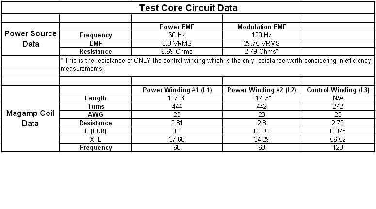
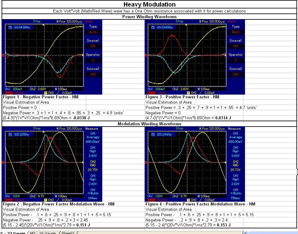
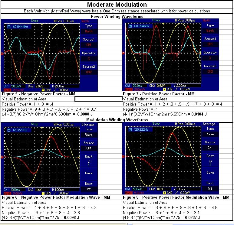
    This is the test circuit that the following data is based off of:

    *Note the capacitance in the diagram is not correct, for Moderate Modulation 10uF was used and for Heavy Modulation, 40uF was used.


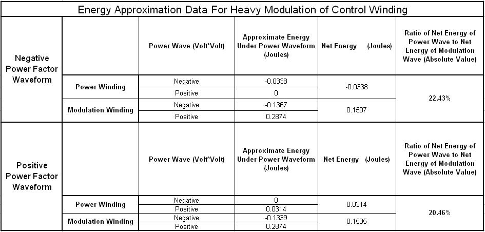
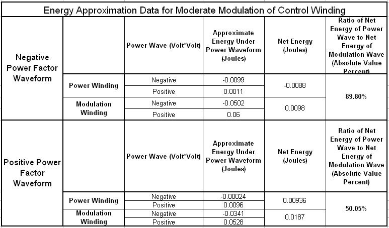
    While this information is nothing to 'call home about', it does show some interesting features of the electrical circuit using synchronous parameter variation. First, take note that in heavy versus moderate modulation, it took less energy to coerce the energy into as a negative power factor than as a positive power factor, possibly opening up question to the Newtonian action/reaction idea. Second, notice how negatively biased the power factor is of the (red wave in the oscilloscope pics, figure 1 & 5) under proper conditions. Just imagine what might happen if a highly-square-hysteresis-loop core was being used. (The core under study was mapped out to be fairly round). Lastly, notice that you cannot just 'yank' the energy out with brute force, the heavy modulation was much worse than the moderate modulation as far as efficiency. There is obviously a balancing act with power consumption and core material. In my observations, I have found that if the carrier wave saturates the core before the modulation wave can saturate the core, the negative power factor will not manifest as strongly. The modulation wave must be the prime mode of core saturation or positive power sneaks into the mix.

    I'm sure I missed some relevant info so feel free to call me out.

    Good Luck,

    Dave
    Last edited by Web000x; 07-13-2012, 03:10 AM.

    Leave a comment:


  • Web000x
    replied
    As promised, here is a bit of information about what I have been doing behind the scenes. It has not reached the stage of development that we are all seeking for yet, but it does provide some valuable insights to the beginning experimenter that could help save a lot of time.

    First of all, let us examine what direction Eric Dollard has been pointing us towards. Examine the waveforms presented in the following diagram:


    Notice that the power wave, P, in watts has an unequal amount of area underneath the curve. In the first diagram, the energy is being produced (the negative area under the power wave is greater than the positive area under the power wave) and in the second diagram, energy is being consumed (the positive area under the power wave is greater than the negative area under the power wave). Analyzing the sinusoidal waves in the graph shows that if the circuit did not have the parameter variation denoted by the wave labeled x, it would exhibit an induction factor of 100% and a power factor of 0%, meaning that this circuit would be a purely reactive circuit, a very high if not infinite magnification factor. This graph clearly shows that under certain conditions of synchronous parameter variation that a negative power factor can manifest in a circuit, meaning that energy is being externally supplied from the varying parameter. Where does the energy come from? That is the million dollar question...

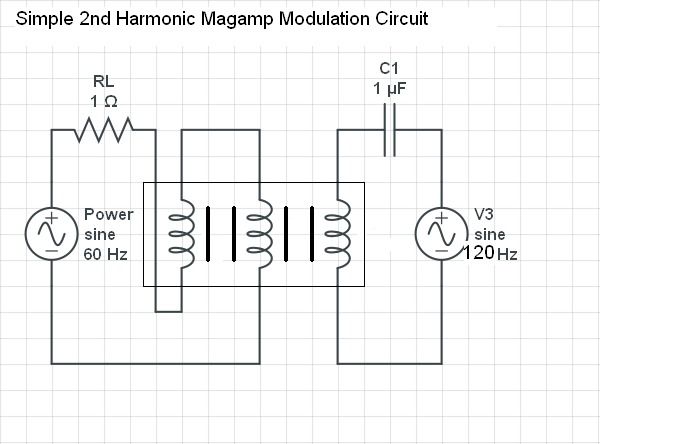
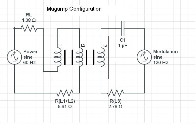
    As suggested by Eric Dollard, how do we construct a magnetic amplifier circuit to use as a means of synchronous parameter variation at the 2nd harmonic of the power wave? If you just simply connect up a circuit like this, complications will occur.


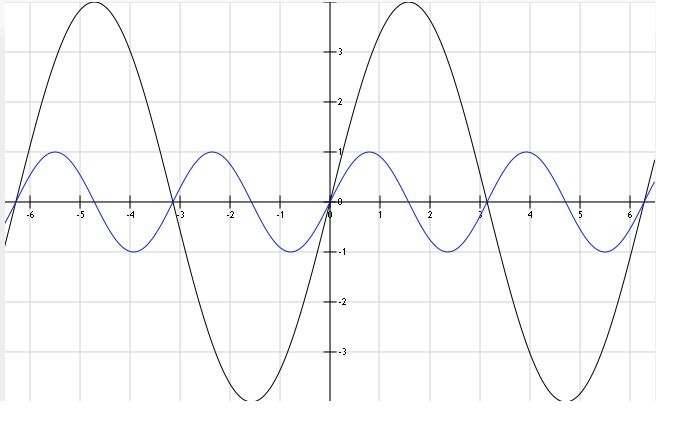
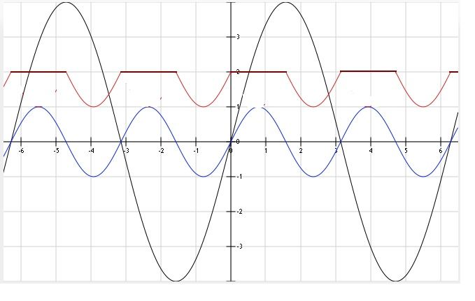
    The above circuit will have the following waveshapes where the function shown in black is the power wave (carrier wave) and shown in blue is the modulation wave:


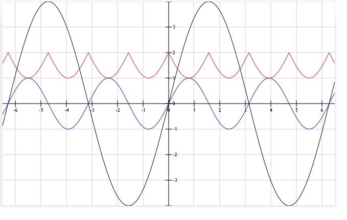
    The above graph seems like it is suited to be the correct waveshape that we want for our modulation, HOWEVER, if you start taking DC inductance measurements for both polarities of ampere-turns in the control winding, you will see that the inductance of the power windings decreases with each half cycle of the modulation wave, giving 4 minimum inductance peaks rather than 2 as shown by Steinmetz's diagram above. A graphical representation can be seen below, inductance colored red:


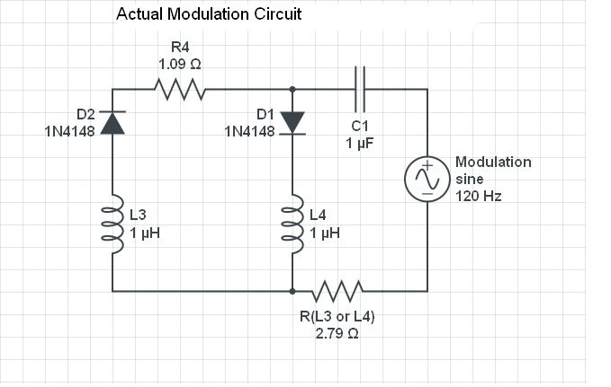
    As can be seen by the series capacitor in the "Simple Second Harmonic Magamp Modulation Circuit", the modulation portion needs to be in resonance to effectively deliver enough current into the impedance (control winding) that will in turn deliver the ampere-turns of magnetism into the core. After many, many hours of trying every damn thing that I could to overcome this problem of the 4x inductance crests/troughs, I found a simple solution. Two identical control windings and a couple of diodes! So easy...

    *R4 is the 1 ohm resistor for current detection.

    This arrangement allows for unidirectional current only in the control winding of the magamp under study. It still doesn't have the sinusoidal shape that Steinmetz's has, but the inductance variation becomes isolated to only two out of the four quadrants of rotation. It has produced the best looking waveforms that I have seen on my scope to date.


    This configuration would be best used on a four phase electrical system. Then all diverted control winding current could be utilized to modulate another core, creating a balanced system.

    This sums up how I have been running my modulation experiments, and I'll be posting some data to accompany this when I can stand to sit down at the computer again.

    Until then...

    Dave
    Last edited by Web000x; 07-13-2012, 01:39 AM.

    Leave a comment:


  • garrettm4
    replied
    Advancements in Hydrolysis & Power Conversion Circuits

    Andrew,

    Thank you for sharing your information on the subject. I have avoided the variable dielectric circuits due to my lacking in funds and resources, but what you have presented gives me much excitement to pursue that route.

    You may have already thought of this, and some A-hole will probably steal this idea, but for the sake of discussion I will give a basic outline of the idea you gifted me with you demonstrations.

    If one were to unite a variable magnetic storage element with the variable water-capacitor, and then drive them from an outside source as an LC tank, with the proper phasing of the control signals, you would have a very efficient and possibly over-unity hydrolysis system.

    If both elements exhibit a negative resistance/conductance characteristic that is greater than the average natural logarithmic decrement, the resonant oscillations would continue to grow until a breakdown in the water capacitor occurred or some other non-linearity in the circuit limited the growth.

    However, if you balanced the total systems exhibited negative resistance (from parameter change) with that of the water capacitors shunted conductance (water conductivity), you would have minimal power supplied from the source supply, except for the control signals and other system losses.

    In principal, it would work like an LC tank that canceled its own internal resistance/conductance. However, in a practical situation, you would need a small amount of positive resistance in the system to limit the magnitude of the oscillation, because if there is no effective resistance in the system, the oscillation will continue to grow logarithmically until something failed.

    An alternate mode of operation is to run the circuit purely through parametric change via the control circuits, as I have experimentally found with the reluctance motor project, natural excitation can take place ONLY if the series resistance doesn't exceed the "critical resistance" of the oscillatory system.

    This mode of excitation falls under the concept of an "under-damped system", when "critically damped" no oscillations take place, but if not loaded to the critical state it will oscillate freely. If the conductivity of the water is explicitly chosen to provide a certain amount of shunt conductance, that doesn't critically damp the system, you could sustain oscillations and disassociate the water molecules for minimal electrical input.

    While there are some technical hurdles with these configurations, I believe that they are worth pursuing for those who are interested.

    ----------------------------------------------

    On another note, I am going to start work on a buck/boost DC-DC converter that implements the general principle of parametric variation. Hopefully, I will have some results worth posting on here for everyone's perusal. I believe this mode to be the most useful at the end of the day, seeing as how almost every modern DC PSU incorporates this type of circuit topology. If this technology is implemented, we can push the limits of efficiency in our modern power conversion circuits into the realm of "over-unity" with a fairly simple design change.

    Below is a very basic example of an electronically controlled saturable reactor or modulated inductor. This configuration could be used with AC or DC-DC circuits with parametric variation applied to return more magnetic induction than the original magnetic induction stored, i.e. more webers returned than webers originally stored. The core would need to be high in Cobalt or Nickle content, for a square hysteresis loop, for this type of design to be of any practical use.


    Some thoughts,
    Garrett M
    Last edited by garrettm4; 07-23-2012, 05:05 PM.

    Leave a comment:


  • Armagdn03
    replied
    Here is another interesting capacity switching device. What you see is a polar dielectric (water) which rearranges its polar orientation when a current flows through it perpendicular to the electric gradient created by the capacitor plates.

    MOV03700 - YouTube

    Leave a comment:


  • Armagdn03
    replied
    A while back I started a thread on this very topic, however I used solid state devices, both capacitive and inductive to achieve parameter variation. The information might be very relevant to what you guys are trying to accomplish.

    Solid State Capacity switching Tube 2 - YouTube


    Cheers,
    Andrew

    Leave a comment:

Working...
X