Announcement

Collapse
No announcement yet.

My Motors got me to Tap into Radiant Energy

Collapse
X
 
  • Filter
  • Time
  • Show
Clear All
new posts

  • Hello JS
    I finally got some time to put on another two fets and there is not even 1/4 degree temp rise above ambient starting temperature. This is compared to finger burning with two fets. Scope shows same sharp square wave. As this board is working great, I will test driver tomorrow on another board without fets attached. Motor runs well with this one four fet board at 25 thru 35 frequency but circuit squeals above that freq.
    Dana
    Last edited by prochiro; 09-14-2013, 05:21 AM. Reason: spelling
    "Today's scientist have substituted mathematics for experiments and they wander off through equation after equation and eventually build a structure which has no relation to reality."
    Nikola Tesla

    Comment


    • Originally posted by prochiro View Post
      Hello JS
      I finally got some time to put on another two fets and there is not even 1/4 degree temp rise above ambient starting temperature. This is compared to finger burning with two fets. Scope shows same sharp square wave. As this board is working great, I will test driver tomorrow on another board without fets attached. Motor runs well with this one four fet board at 25 thru 35 frequency but circuit squeals above that freq.
      Dana
      Hello Dana, did you do exactly the same tests, with the 4 fets, as with the 2 fets, if so do you think the driver is overdriving the two fets on these boards?

      Regards Cornboy.

      Comment


      • @Cornboy
        Months ago I built a three fet setup and reported that for the first time on many single JS design boards there was no heat and motor was happy. John convinced me to go back to two so I did but added a lot of solder and that also yielded also no heat and happy motor. I set up four boards on one and made the larger boards I now use for the Imperial and Imperial was happy. Now along comes the black beauty, JS design and I built Eight. All got hot with two fets, even on a smaller motor. I added two more fets and got no heat and happy motor.

        Yes, I think we were over driving a bit and as I have stated several times, I think the heavy solder was taking up the slack as capacitance. I think the problem is that John built a circuit that is too powerful for two fets. (Over-driving) is a good description. In my humble opinion, we now have all the control needed for the Imperial running a generator and running a bike that we need. The last word still need to be said about this, but I feel at this point that JS will agree this is the next direction with black beauties. anyone can add another fet on reverse side by simply soldering one (be careful about keeping all fet pins together correctly) to the opposite side. Kogs, if you love your wife, DO THIS.
        Dana
        "Today's scientist have substituted mathematics for experiments and they wander off through equation after equation and eventually build a structure which has no relation to reality."
        Nikola Tesla

        Comment


        • Originally posted by Cornboy 555 View Post
          Hello JS, and all, have been doing more testing, and confusing my self, havn't got a handle on this scope yet.

          .....


          [IMG][/IMG]

          This shot is 1us of 30nf cap load.

          Regards Cornboy.
          Sorry for late answer - interent was broklen for a day.
          Well, this is another pit you fell in - sorry for that. But lots of education possible.
          Any automatic function is exatly what it says - it perfomrs a predefined algorithm and is not able to account for non expected or false results. Your scope shot is just an example of that. depending on how much of the true graph your automatic rise time calculation sees, it computes different results. In this case it accounts the time up to the peak value displayed.
          Let's alter our strategy in order to get you an solid grounds:
          • catch your pulse at scope
          • oprate zoom up to 5nS / div in order to see edge zoomed
          • read the steepness of the slope just in linear area

          How can you perform that reliably?

          Let's take this pic as example:

          - Set GND level of your beam to bottom grid line
          - Increase vertical amplification to about 2V/div in order to use as much screen as possible.

          Now we are going to measure relatively in order to get the steepness.
          - operate x/y signal shift dials at your scope in order to align the estimated start point of linear section to the next cross point of screen grid.
          - now follow the linear signal path 1,2,3... horizontal or vertical grid lines (depending on length of linear section). In fact you take the last grid line intersection with linear signal area (vertical or horizontal)
          In the above example your reading will be about 4ns per 5V. As we are interested in 10V (FET fully open) we note 8nS per 10V.
          Thus we can estimate switch on or off time at any condition.

          If you are still confused please post 2 different pics with zoomed signal (GN D= bottom grid line, amplification 2V per div) if possible start of linear area adjusted to a cross point of grid lines (but not essential)
          Sorry no shortcut just now - but tons of chances to learn.

          @ALL: If anyone of you get monster PCBs from Oshpark with double sided copper please I prdict that copper sucks lot of soldering heat. As it is double sided it will suck heat twice. With normal recommended soldering tempoerature you will not get it soldered. You need to increase temperature above 380 centdegree and solder quick.
          JS
          Experts spend hours a day in order to question their doing while others stopped thinking feeling they were professionals.

          Comment


          • Hello JS
            I am positive that your boards will be double copper sided. That changed as soon as Sam asked them to do it. I solder quickly at 800 F and if you just stick the tip of solder into flux, no real visible amount, it flows smooth. One other tip for first timers, keeping the tip of your iron clean by sponge or metallic pad keeps the oxidized material off the tip and heat transfers fast. When cleaning tip, keep the angle low to pad so the cleaning is even over the length of tip and not just at the vary end. The finer the tip used, the better.
            Dana
            "Today's scientist have substituted mathematics for experiments and they wander off through equation after equation and eventually build a structure which has no relation to reality."
            Nikola Tesla

            Comment


            • Hey Dana

              That's great news, that you tested the double fets. I was going to change those resistors this weekend, but I will double fets first.
              I got the other imperial rewound last night, I tried to go a little faster, less working wires initially, to see if i could get production costs down. Not good, only doubled the work on the outer coils. You need to work these coils from number 1 to 28. Really intense motors to wind.
              Milling a plate today to try and use imperial frame in gen without shortening frame, looks good so far.

              Cheers
              Machine

              Comment


              • Count of FETs used:
                I accept your findings, more FETs to stay cooler and I can explain it. Remember I talked in the past of proper cooling!

                Look at the diagrams below! Please note those values regard 50% duty cycle:
                A:B:C: Third diagram assumes a heat sink of 2"X"2X1.5"
                Things get better

                D: fourth digram shows how we can make things even better if we use a simple CPU cooler with fan (1K / Watt). I really refer to simple ones out of old PCs like Pentium. Current sophisticated ones go down to 0.25 K/Watt and better.


                As you can see 2 FETs being cooled properly can be as good as 4 FETs being hot at their limits. For high performance you need 4 FETs superiour cooling included.
                Basically heat dissipation and temperature perform linearly. But our feeling regarding power is fooled because the current enters squared into the formula. (P=I*I*R) Humans need to be thoroughly trained in order to get such behaviour estimated correctly. We here - including me - get fooled if we are not alert!
                I hope all of you can now read those diagrams and estimate what type of measures you need to decide for and where to be alert.

                If you feel this is no "cool" design - IT IS! Compared to transistor circuits it is damn cool! Sorry! Above notions is bare and true physics. Unless we operate bare radiant we can't omit cooling.

                The temperatures given above in diagrams refer to internal semiconductor chip. Of yourse you will not mearue them at the ends of your heatsink. Heat flow behaves like resistors in series (resistance against heat flow):
                • Semiconductor chip to case : 0.26 K/Watt
                • Now you decide if without cooling: 62 K/Watt
                • Or you decide for CPU cooling: 1 K/Watt
                • Or anything inbetween: ????
                Last edited by JohnStone; 09-14-2013, 05:34 PM.
                Experts spend hours a day in order to question their doing while others stopped thinking feeling they were professionals.

                Comment


                • Pulsing Pulsed Motors...

                  Originally posted by adversarius View Post
                  Hi All

                  I asked in the Asymmetric Machines thread what the advantages are of pulsing the motors. Is it just to bring down input power and/or for recovering the field collapse of the coils?

                  So, it seems to me now that turning the coils on and off is achieved by the asymmetrical architecture of the motor and not by a pulsing-circuit (like in the Bedini circuit)?

                  The first pulse motor I learned about was the Bedini, so my knowledge of those motors is quite influenced by this principle. The Bedini circuit can remove the BEMF as well and allow for storing the energy (of the field collapse) in a secondary battery, so it does not oppose the rotation. Is this comparable to the principle of asymmetric machines?

                  Regards

                  adversarius

                  Hello Adversarius and Welcome,

                  I am sorry I did not respond before, I was extremely busy for the past few weeks...and still would be...but I made a "stop" to keep Thread posted and up to date.

                  I will try to be brief, you have made very good question(s)

                  The Asymmetric Machines I have displayed in my other Thread does pulse "Internally" by intrinsically Opening (Off Time) and Closing (On Time) all their operating coils/pairs or groups during rotation. They could be fed linearly like it has been observed so far in all of them...However, picture it this way...when we pulse also, our Source (Feed) to this Machines, We are creating a Network Protocol of In-Out Signals between a server (Our Controllers Assembly) and the client (Our Motors).
                  For example, If We pulse a Symmetrical Machine, which is based in a Constant Closed Circuit within to perform a rotation...Our Server (Controller) Signals would be crashing/collapsing in a front end collision at all times within that Symmetrical Machine...they are a "Dead End Street"

                  In Asymmetrical Machines we send a pulse that will trigger a certain number of coils ONLY[Not ALL like Symmetry Does](depending of the Time On duration, Frequency, Duty or more clever configurations like the Four or Six Monster Pulsers through Arduino Microprocessor, etc)...Then those triggered/energized coils would go Off at certain angle of rotation in order to allow other incoming coils to repeat process.

                  If You get a Four Brush set motor and simple pulse-control (like with a simple 555 timer oscillator in Astable Mode) just pulsing Motor Input (Two set of brushes) while reading your output on generator side ...You will get the Machine response/pulse out, it is operating at...so the proper adjustments could be done to "align" or equalize Input Signals to Operating Motor signals...it is NEVER a "Dead End Street" here.

                  As you could also do this testing with even smaller versions of just Two set of brushes...One set Input, One set output.

                  No matter how we do this pulsing..We will NEVER be sending our controlling pulse signals to a "Front End Collision Center" like in Symmetrical occurs...But, instead, it would be a "Looping" of signal communication between Controller-Machine...a much better approach as all could realize.

                  What I am trying to basically explain here, is that We have a real Networking Protocol of Communication between our Machines and our Controlling Signals that will allow a much better driving at any speed torque we desire to take them to.

                  I will try to give you an example in Automotive Driving...

                  When we drive a Stick Shift or even a Manual transmission Vehicle...(and of course, we all 'supposedly' know what we are doing...lol)...

                  When we accelerate with one gear on, we must watch our RPM Meter...to see where it remains steady ...it will go No Further...so we change to next gear...when next gear is coupled, RPM's will decrease drastically...then it is our time to accelerate the gas pedal...till we observe again the RPM's steady to a Max point...and so on...right?

                  Well, this is a "Manual" method to establish a Driving Protocol...and actually we are "Pulsing" the Gas Feeding at the right timing based on just the RPM's parameter...So say we feed this vehicle in a "linear fashion"...not observing RPM's...we end up "Burning Up" or wearing out the Clutching/Engaging Mechanisms...

                  In our Machines we could establish an "Automatic Cruise Control" circuit, based on Motor feedback from our Input signals...and that's the stage we are now, by adding not only RPM's sensors...but Amperage/Voltage and Frequency to our Systems.

                  We will move further on...into "Brushless Asymmetric Machines"...with Hall Sensors driving coils timing, just like a Symmetric BLDC Motor does. Limitations in the beginning would be the use of permanent magnets...However, further on we will be able to have wound and independent (self feed) rotors by Capacitors/Inductance Feeding...not now, not yet.

                  Hope this post helped You to understand Your concerns.


                  Kind regards


                  Ufopolitics
                  Last edited by Ufopolitics; 09-14-2013, 05:19 PM.
                  Principles for the Development of a Complete Mind: Study the science of art. Study the art of science. Develop your senses- especially learn how to see. Realize that everything connects to everything else.― Leonardo da Vinci

                  Comment


                  • Last edited by Ufopolitics; 09-14-2013, 05:17 PM.
                    Principles for the Development of a Complete Mind: Study the science of art. Study the art of science. Develop your senses- especially learn how to see. Realize that everything connects to everything else.― Leonardo da Vinci

                    Comment


                    • Comment


                      • Hello and Welcome NTC


                        Hello and Welcome ntc !

                        I am very glad you have made so many testing with this original Coil set up...It's been a while since I do not "play" with this...

                        Ok, a CFL depends on its Wattage for it to draw a certain amperage, I have run up to 125 W CFL rating (equivalent to 600 Watts Incandescent Lamp) .

                        Have you watched my YT Videos related to Radiant Energy ?

                        RADIANT FREE ENERGY - YouTube

                        As I also recommend:

                        DEFINING RADIANT ENERGY FIELD (Part 1) - YouTube

                        The Green Light is just an "Spectrum" that occurs in very short time...to a point it is not visible to our naked eye...just play back your own videos...then your camera IR and Electronic fast Capturing shutters will do show it...

                        Watch RADIANT_ ENERGY_ULTRAVIOLET_SPECTRUM_GREEN_STROBE - YouTube

                        Notice that I have to replay video at very slow motion...in order to see the Green Light in normal development for our eyes...However, also notice the UV Spectrum...spreading at environment nano seconds before green strobe...

                        Related to the Motors you are running...they are too High End for the small coil and set up you have...and that is what I meant when I wrote that sentence...Fields, Magnetic Fields MUST be balanced in order to achieve the Effect. If You try a smaller motor, like the Goldmine Five Poles (550 Body) they will run cold.

                        Why Coils must match?...Why do we need a bigger battery bank to run properly certain Symmetric Motors?...same thing. Our Radiant Field Capacity depends upon the Geometry and size of our Coils...Think about the Wardenclyffe Tesla Coil...

                        You could have a bigger Capacity Coil and run smaller motors very cold...however, when you install a brushed symmetric motor that would demand a higher draw from coil...it would overheat either one of the two Fields (Motor Coils or Supplying Coil ).

                        How do You know your Symmetric Motor Total Coil Resistance?...Easy, just find the attaching point where two wires reach same commutator element hook, it is normally one single wire that "lands" to each hook then keeps going to coil, then to hook and so on till that finishing ending hook...that's starting and end point when they wound it...separate it by spreading/opening hook...just release from hook one terminal (normally is the last wire that was hooked)...then measure resistance from terminal at hook and loose wire end...that's the Total Resistance from Coil when your Motor is running...then replace wire and press hook back...Your Coil Must be Equal or Above that resistance value.

                        There is more about this...and it occurs that when using a higher capacity motor...drawing more current...then Hot flow over rides Radiant flow within circuit...that is when I did the "Happy Motor" Circuit...and Member Kogs (Ian Koglin) from Australia has made many tests with this set up.

                        The Happy Motor uses a Secondary Coil to run from Primary...where there is no ferrite nor steel core, but Air...what happens is that we are weakening the Hot Field by doing this...since Hot will only induce a Secondary through a ferrous core...then Secondary would be a higher percentage of Radiant Energy and minimum hot.

                        At this point I could not find my original diagram for this...so if anyone has it...please post the "Happy Motor" schematics, thanks!

                        How could you know it is Radiant?

                        Simple, use a neon bulb at the reverse side...Radiant is a Purple Plasma Ball, Hot is an Orange light like the Normal one you always see on Neons......it will manifest ONLY at very low pulses 6 to 8 Hertz...

                        RADIANT ENERGIZED NEON - YouTube

                        Finally, related to Batteries versus Power Source Unit...I rather use batteries...preferably SLA (I have used LiPo's...but they say they are dangerous...) so I only recommend them at your own risk......However, a PSU We could administer the Amperage draw...so, it would be interesting to see the development when lowering current input under load at Coil Output.
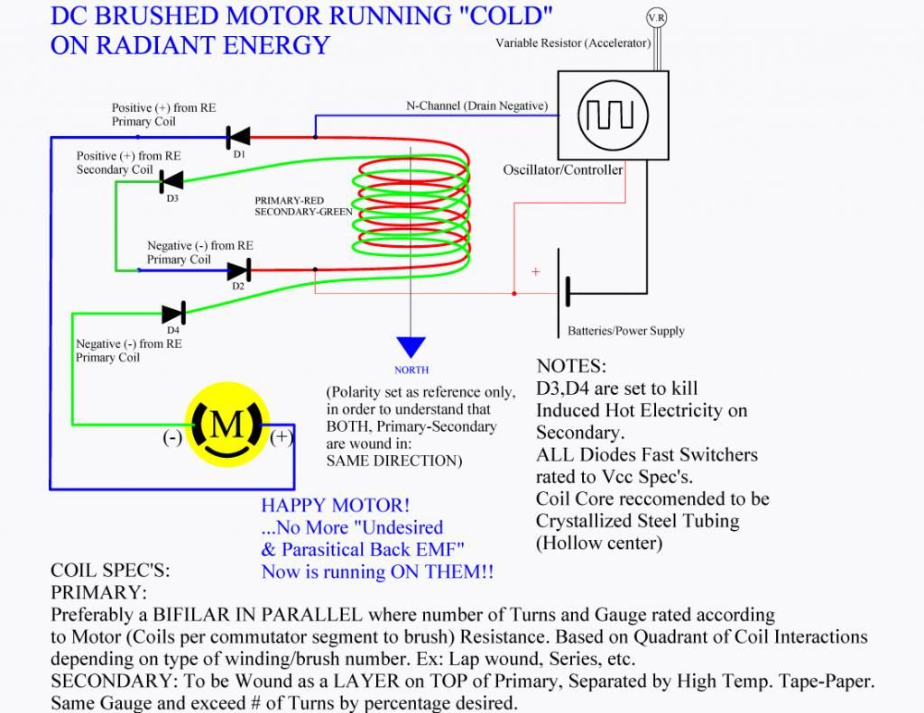
                        Thanks again, and hope this helped you.


                        Regards


                        Ufopolitics
                        Last edited by Ufopolitics; 09-15-2013, 02:32 AM.
                        Principles for the Development of a Complete Mind: Study the science of art. Study the art of science. Develop your senses- especially learn how to see. Realize that everything connects to everything else.― Leonardo da Vinci

                        Comment


                        • Hello NTC


                          Hope this helps
                          Dana
                          "Today's scientist have substituted mathematics for experiments and they wander off through equation after equation and eventually build a structure which has no relation to reality."
                          Nikola Tesla

                          Comment


                          • Originally posted by Ufopolitics View Post
                            ...
                            I have a question which is related , however, it would take us a step further on the EV Systems that also would apply to Stationary Systems like the Motor-Generator Sets.

                            In my E-Bike,..... I will post a simple diagram of all this later on......
                            Hi Ufo,
                            still waiting for diagram!
                            Basically your intention seems to be viable (as I understood your words). The implication is usually that controllers perform all kind of checks and supervision at important circuit parts. This might cause them to enter a safety or emergency mode and that is not what we expect.

                            @ALL: As Ufo experienced a FET driver needs to be double supervised in order to prevent total loss. The problem is that FETs increase their resistance if they get hot. One FET failing causes others to increase their resistance as well ..... -> that is a so called domino effect!
                            This is the reason industry likes IGBTs for severe power applications. They behave inversely and hence somewaht more safe. For our applications it is not necessary using IGBTs.

                            Measures for safe FET operation:
                            1. Use a fuse being adapted to your current application.
                            2. Provide an emergency switch at your setup in order to imediately stop current in case of damage.
                            3. Use of a temperature sensor at FETs (definitely an issue for next driver desing)
                            JS
                            Experts spend hours a day in order to question their doing while others stopped thinking feeling they were professionals.

                            Comment


                            • For ufopolitics - thank you and questions about cold dc motor

                              Originally posted by Ufopolitics View Post
                              Hello and Welcome ntc !

                              I am very glad you have made so many testing with this original Coil set up...It's been a while since I do not "play" with this...

                              Ok, a CFL depends on its Wattage for it to draw a certain amperage, I have run up to 125 W CFL rating (equivalent to 600 Watts Incandescent Lamp) .

                              Have you watched my YT Videos related to Radiant Energy ?

                              RADIANT FREE ENERGY - YouTube

                              As I also recommend:

                              DEFINING RADIANT ENERGY FIELD (Part 1) - YouTube

                              The Green Light is just an "Spectrum" that occurs in very short time...to a point it is not visible to our naked eye...just play back your own videos...then your camera IR and Electronic fast Capturing shutters will do show it...

                              Watch RADIANT_ ENERGY_ULTRAVIOLET_SPECTRUM_GREEN_STROBE - YouTube

                              Notice that I have to replay video at very slow motion...in order to see the Green Light in normal development for our eyes...However, also notice the UV Spectrum...spreading at environment nano seconds before green strobe...

                              Related to the Motors you are running...they are too High End for the small coil and set up you have...and that is what I meant when I wrote that sentence...Fields, Magnetic Fields MUST be balanced in order to achieve the Effect. If You try a smaller motor, like the Goldmine Five Poles (550 Body) they will run cold.

                              Why Coils must match?...Why do we need a bigger battery bank to run properly certain Symmetric Motors?...same thing. Our Radiant Field Capacity depends upon the Geometry and size of our Coils...Think about the Wardenclyffe Tesla Coil...

                              You could have a bigger Capacity Coil and run smaller motors very cold...however, when you install a brushed symmetric motor that would demand a higher draw from coil...it would overheat either one of the two Fields (Motor Coils or Supplying Coil ).

                              How do You know your Symmetric Motor Total Coil Resistance?...Easy, just find the attaching point where two wires reach same commutator element hook, it is normally one single wire that "lands" to each hook then keeps going to coil, then to hook and so on till that finishing ending hook...that's starting and end point when they wound it...separate it by spreading/opening hook...just release from hook one terminal (normally is the last wire that was hooked)...then measure resistance from terminal at hook and loose wire end...that's the Total Resistance from Coil when your Motor is running...then replace wire and press hook back...Your Coil Must be Equal or Above that resistance value.

                              There is more about this...and it occurs that when using a higher capacity motor...drawing more current...then Hot flow over rides Radiant flow within circuit...that is when I did the "Happy Motor" Circuit...and Member Kogs (Ian Koglin) from Australia has made many tests with this set up.

                              The Happy Motor uses a Secondary Coil to run from Primary...where there is no ferrite nor steel core, but Air...what happens is that we are weakening the Hot Field by doing this...since Hot will only induce a Secondary through a ferrous core...then Secondary would be a higher percentage of Radiant Energy and minimum hot.

                              At this point I could not find my original diagram for this...so if anyone has it...please post the "Happy Motor" schematics, thanks!

                              How could you know it is Radiant?

                              Simple, use a neon bulb at the reverse side...Radiant is a Purple Plasma Ball, Hot is an Orange light like the Normal one you always see on Neons......it will manifest ONLY at very low pulses 6 to 8 Hertz...

                              RADIANT ENERGIZED NEON - YouTube

                              Finally, related to Batteries versus Power Source Unit...I rather use batteries...preferably SLA (I have used LiPo's...but they say they are dangerous...) so I only recommend them at your own risk......However, a PSU We could administer the Amperage draw...so, it would be interesting to see the development when lowering current input under load at Coil Output.

                              Thanks again, and hope this helped you.


                              Regards


                              Ufopolitics

                              Comment


                              • Hello NTC

                                All the diodes are the same. Electronic goldmine is the company and G18945 (Clickable) is the number of motor we use.
                                Dana
                                Last edited by prochiro; 09-16-2013, 02:59 AM. Reason: spell edit
                                "Today's scientist have substituted mathematics for experiments and they wander off through equation after equation and eventually build a structure which has no relation to reality."
                                Nikola Tesla

                                Comment

                                Working...
                                X