Announcement

Collapse
No announcement yet.

The ultimate secret of free energy: Split the postive AND the negative

Collapse
X
 
  • Filter
  • Time
  • Show
Clear All
new posts

  • lamare
    replied
    Some more on Cymatics.

    First a bit about what Cynematics is:
    The Structure and Dynamics of Waves and Vibrations by Hans Jenny

    When Jenny experimented with fluids of various kinds he produced wave motions, spirals, and wave-like patterns in continuous circulation. In his research with plant spores, he found an enormous variety and complexity, but even so, there was a unity in the shapes and dynamic developments that arose. With the help of iron filings, mercury, viscous liquids, plastic-like substances and gases, he investigated the three-dimensional aspects of the effect of vibration.
    Basically, you have some particles floating in a fluid and vibrate that with sound.

    An interesting phenomenon appeared when he took a vibrating plate covered with liquid and tilted it.The liquid did not yield to gravitational influence and run off the vibrating plate but stayed on and went on constructing new shapes as though nothing had happened. If, however, the oscillation was then turned off, the liquid began to run, but if he was really fast and got the vibrations going again, he could get the liquid back in place on the plate. According to Jenny, this was an example of an antigravitational effect created by vibrations.

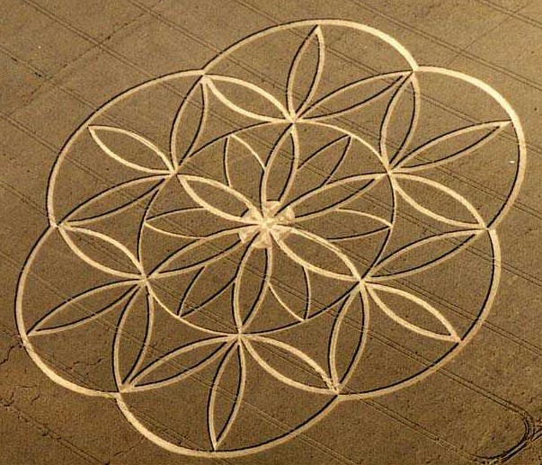
    Now take a look at this picture:

    See this ball-like structure in the centre?

    Two questions to think about:
    1. What force makes the matter stick in that centre?
    2. What would happen if you would rotate this whole thing?


    And then look at this:


    Its like a three dimensional execution of the iron filings test but much more mesmerizing.
    Why does magnetism do the same things?
    Last edited by lamare; 08-31-2010, 06:24 PM. Reason: replaced picture, cause appears to be unavailable often.

    Leave a comment:


  • DrStiffler
    replied
    Originally posted by CosmicFarmer View Post
    @DrStiffler

    What is a DEB? I have not seen you reference it at all until now. I can understand the D means dual, maybe the E means Exciter, and the B might mean broadcasting?

    Were those 18-1 boards, or could an 18-1 board be used for that?

    Looking at the picture, I see 2 different sized L3 coils that each has an output that forms another bifilar coil with capacitive coupling. The difference between oscillations should be great and make quite a mess for radios, as well as each exciter affecting each other in a very dynamic way. Could you incorporate a S-gate into that design somehow? Or were you just trying to push your wireless field as far as it would go, and then design a resonant load?

    In my opinion, the AV plug is a crude way to harvest the cohesion, because when one frequency is low another might be high, and all the AV plug does is gather the average difference at that moment. That is why the other exciters seem to work the same as their frequencies are limited to just a few and therefore seem stronger... I may be wrong though...

    If being a senior member on an alt. E board with wideband jamming experimental circuits for sale isnt enough to send you to fema, then nothing is. An improved instrument is just that. I hope that these events do not come to pass, however.

    Anyway, Didn't want to rain on your parade, but just wanted to let you know you cant be a "half-virgin" or "Kind-of" pregnant... If you get my drift. Just go full strength wherever you decide to go. I'm glad your awake and trying to make a difference.
    @CosmicFarmer

    A few more answers to your questions.

    In my opinion, the AV plug is a crude way to harvest the cohesion, because when one frequency is low another might be high, and all the AV plug does is gather the average difference at that moment. That is why the other exciters seem to work the same as their frequencies are limited to just a few and therefore seem stronger... I may be wrong though...
    Well is this right? You are with an AV Plug Rectifying AC, correct? and so long as the diodes have a low capacity and a high frequency response, do you not turn all the AC into DC? Isn't the AV Plus a wide-band converter to DC?

    Edit: Conrad just got all over me. Which domain are we speaking? You view a WB signal on a scope and it shows a silly wave with distortion, yet vie in the frequency domain and you see the real content. Isn't that scope view of the wave containing the sum of the energy??

    If you were to have access to the formula that describes SEC you would see that the total energy when added across the radiation spectrum (of the exciter) is larger than the input to the exciter. Granted a flat or wide-band load is required to realize this, yet the simple little AV Plus will do it fine.

    A properly operating SEC Exciter will have energy spikes out to at least 500MHz, this can be confirmed by anyone with and SA.

    If being a senior member on an alt. E board with wideband jamming experimental circuits for sale isnt enough to send you to fema, then nothing is. An improved instrument is just that. I hope that these events do not come to pass, however.
    ? And no this is not a member of the 'Blue Man Group'.
    "half-virgin" or "Kind-of" pregnant...
    Really, I thought it was so, kind of like a Revolution, not real until the first shot!
    Last edited by DrStiffler; 08-27-2010, 05:18 PM.

    Leave a comment:


  • DrStiffler
    replied
    Originally posted by CosmicFarmer View Post
    @DrStiffler

    What is a DEB? I have not seen you reference it at all until now. I can understand the D means dual, maybe the E means Exciter, and the B might mean broadcasting?

    Were those 18-1 boards, or could an 18-1 board be used for that?

    Looking at the picture, I see 2 different sized L3 coils that each has an output that forms another bifilar coil with capacitive coupling. The difference between oscillations should be great and make quite a mess for radios, as well as each exciter affecting each other in a very dynamic way. Could you incorporate a S-gate into that design somehow? Or were you just trying to push your wireless field as far as it would go, and then design a resonant load?

    In my opinion, the AV plug is a crude way to harvest the cohesion, because when one frequency is low another might be high, and all the AV plug does is gather the average difference at that moment. That is why the other exciters seem to work the same as their frequencies are limited to just a few and therefore seem stronger... I may be wrong though...

    If being a senior member on an alt. E board with wideband jamming experimental circuits for sale isnt enough to send you to fema, then nothing is. An improved instrument is just that. I hope that these events do not come to pass, however.

    Anyway, Didn't want to rain on your parade, but just wanted to let you know you cant be a "half-virgin" or "Kind-of" pregnant... If you get my drift. Just go full strength wherever you decide to go. I'm glad your awake and trying to make a difference.
    @CosmicFarmer
    Wish we had a bit of rain here, welcome, welcome it would be, 107'F yesterday.....

    Go to the web site and in the site content link go to the SEC Lexicon, that's about all I can say about it.

    Oh and do it soon, www.drstiffler.com is now gone and Stiffler Scientific will be gone early Sept., with the UN running the assignments now I'm out of here.

    Leave a comment:


  • CosmicFarmer
    replied
    @DrStiffler

    What is a DEB? I have not seen you reference it at all until now. I can understand the D means dual, maybe the E means Exciter, and the B might mean broadcasting?

    Were those 18-1 boards, or could an 18-1 board be used for that?

    Looking at the picture, I see 2 different sized L3 coils that each has an output that forms another bifilar coil with capacitive coupling. The difference between oscillations should be great and make quite a mess for radios, as well as each exciter affecting each other in a very dynamic way. Could you incorporate a S-gate into that design somehow? Or were you just trying to push your wireless field as far as it would go, and then design a resonant load?

    In my opinion, the AV plug is a crude way to harvest the cohesion, because when one frequency is low another might be high, and all the AV plug does is gather the average difference at that moment. That is why the other exciters seem to work the same as their frequencies are limited to just a few and therefore seem stronger... I may be wrong though...

    If being a senior member on an alt. E board with wideband jamming experimental circuits for sale isnt enough to send you to fema, then nothing is. An improved instrument is just that. I hope that these events do not come to pass, however.

    Anyway, Didn't want to rain on your parade, but just wanted to let you know you cant be a "half-virgin" or "Kind-of" pregnant... If you get my drift. Just go full strength wherever you decide to go. I'm glad your awake and trying to make a difference.

    Leave a comment:


  • DrStiffler
    replied
    Negative Mass?

    @lamare

    Dr. Koontz has tried to convince me that my SEC Theory may be wrong and that he feels it can be explained by his work which contains negative mass electrons, protons, and photons.

    Web Site of Dr. Robert W. Koontz* www.DoctorKoontz.com

    I think in my last communication with him I upset him by my view of how I might interface his view with mine. In order to resolve in my feeble mind what he is speaking about I stated that the particles would therefore be traveling in the opposite direction of mass particles (think this is where he stopped talking).

    Anyway if we work with negative mass, why not negative time?, its only a measuring stick, right? Anyway if you use the negative mass approach it can be worked into SEC by considering -t, thereby the whole (sum) of the change in the Lattice equal 0, humm...

    Anyway I have included another picture of your receiver idea where the load does not load.

    http://67.76.235.52/images/wake00.jpg
    Last edited by DrStiffler; 08-27-2010, 04:09 PM.

    Leave a comment:


  • lamare
    replied
    Originally posted by DrStiffler View Post
    Why might you want to work in such a low area of the spectrum when the Lattice has a relaxation time in the Tera Hertz range? When working at the higher end of the spectrum the component bulk and foot print is of course much smaller and the conversion down to usable energy is not a concern as the Coherence can be obtained without this in mind.
    @Doc: Take a look at this:


    If every ball in the upper picture is a piece of matter, a localized electromagnetic wave, and these are inside some kind of lattice as depicted in the lower picture, then you can always find a higher "octave" where you get the same picture again. In other words: the lattice must be recursive, it's a fractal...

    So, if we have an ether, which has matter-like charactistics (fluid,gas) and we *know* that the matter we know are localized EM waves, then it is not hard to postulate that the "elemental" particles of which the ether consists would be very similar and would also be localized EM waves.

    Basically, just a matter of raising the frequency, right?


    Makes you wonder: World Top Secret: Our Earth Is Hollow!: Welcome

    Update:
    It suddenly seems tempting to rephrase Tesla:

    It seems logical to think of the Lattice as being fluid like, since that is what we know the ether is like. If they're really the same thing, then the lattice would be dynamic. At some places, it would be more like a gas, at some places, it would be more like a liquid.... And if that would really be the case, then you would really have a hard time maintaining that the speed of light is fixed across the universe, as Thornhill has said all along, cause the speed of waves traveling trough a medium depends mostly on the density of the medium at hand, as well as on the rigidness and dynamics of the structure (chrystals, Lattices, covalent bonds, etc.) the particles that make up the medium are in, which is a.o. dependent on the temperature. And that is basically synonymous with the amount of energy being available, cause heat is nothing other than infrared light.

    Continueing in this line of thinking: if the ether really is fluid like and the "elemental" particles like quarks that make up matter are really just about the same as the matter we know, just oscillating at a higher frequency, then suddenly you will also have a very hard time maintaining that traveling at speeds higher then the speed of light is impossible. Cause since if the ether is fluid/gas like and we know we can travel trough these at speeds much greater than the speeds at which waves travel trough these media, then you are really looking at exactly the same kind of thing, just at a different scale.

    And then, suddenly, you also have a hard time maintaining the hypothesis posted here is an impossibility: http://www.energeticforum.com/renewa...tion-ufos.html

    Update 2:
    Eric Dollard really deserves to be quoted here also:


    Whatever the general media is around us, call it the ether, or air or you can transmit it through the ground. Basically it just flows.
    In a newspaper article I was looking through the other day I saw that the physicists now have an even bigger magnet so they can smash atoms ever harder and find more little tiny fragments to catalog and confuse themselves. What could be quirkier than a quark? (laughter)
    Gotta love the man:

    Update 3:
    And then take a look at what you can do with standing soundwaves in a fluid, called "Cymatics".
    Cymatics - Wikipedia, the free encyclopedia

    Just google for that and look at the images Google shows you, f.e.:

    Cymatics | | MECHA fushigi | mechanism of MAKA fushigi :


    Last edited by lamare; 08-27-2010, 03:21 PM.

    Leave a comment:


  • lamare
    replied
    @Doc: I shouldn't worry too much about how the energy is being cohered. Energy is being cohered all the time. We just never noticed it does so every time we "discharge" a capacitor. See my article:
    Article:Free Electric Energy in Theory and Practice - PESWiki

    There is an essential difference between the Newtonian analogy we use in electrical engineering (closed circuits) and the actual reality. The analogy of a capacitor in hydraulics (Newtonian analogy) is a piston moving back and forth in a closed cylinder wherein gas is pressurized. There is an essential difference, however. Imagine moving the piston inwards, pressurizing the gas, and put the thing on your workbench. The piston will immediately move back, because of the gas pressure. Now charge a capacitor and put it on your workbench. See the difference? The capacitor will just sit there, keeping it's charge. In other words: our hydraulic analogy is unstable, it 'wants' to release it's energy, while our actual electrical component is stable when 'pressurized'. It will only 'release' it's energy when something external is being done. It has to be disturbed, because the charges in a capacitor actually attract one another, which makes them like to stay where they are. So, when 'discharging' a capacitor, as a matter of fact, these attraction forces have to be overcome. And that does not release energy at all, it costs energy to do that. So, it actually takes the same amount of energy to charge a capacitor as the amount of energy it takes to discharge the capacitor.

    [...]

    Any charge continously emits an energy field, an electric field, spreading with the speed of light, which is the real energy source that makes our circuits run. This energy-field, generated by the charges in our wires, is not created out of thin-air. Since there is a continuous flow of energy out of every charge, there also is a continuous flow of energy going into every charge. And that is where the energy eventually comes from, right from the vacuum itself. For our purposes, it doesn't really matter how the energy that ends up in the electric field is being taken out of the vacuum. It may be ZPE, it may be a "virtual partical flux", it may be anything. It doesn't matter, because we don't need to know.

    All we need to know is that somehow, some form of energy flows into each and every charge in the universe and this energy flow is continuously converted into an outflowing electric energy field by each and every charge in the universe, 27/7, 365 days a year, for free.
    @All,

    Take a look at what I posted here:


    See the similarities and the parallels?

    Meyer basically tried to use fast switching pulses, high bandwidth, eventhough he got his balancing wrong. This is in a way similar to what you do with the SEC circuit, if I understand this right. However, coils are basically current driven, so if you want to drive a coil using voltage pulses trough coupling caps, Doc is right: you need fast switching and a very high bandwidth.

    Now take a look at how Puharich does it.
    You basically have an AM modulated signal, where he does the half wave rectification at the front.

    However, if you would use two AV plugs at the back, and drive two sets of identical coils this way, you should be able to basically construct a sort of dual AM receiver, without the need for fast switching. I think that would be much more elegant...
    Last edited by lamare; 08-27-2010, 09:28 AM.

    Leave a comment:


  • SeaMonkey
    replied
    Originally posted by crackahcrackah View Post
    ...
    If you go to youtube and search for "tesla hairpin" you will see the most basic means for separating transverse waves from longitudinal waves (separating the current from the voltage/field), or as I believe Gray called it, splitting the positive. IT would be great to see more focus on these patents as they are the most important ones which Tesla put out regarding "radiant energy"

    ...

    Onward!
    That is what we call a "Resonant Transmission Line
    Standing Wave."

    The so called "hairpin" is a length of parallel conductor
    transmission line which is shorted at the end opposite
    the input end.

    At resonant frequencies stationary nodes will position
    themselves at appropriate fractional wavelength
    distances along the length of the line.

    The Maximum Voltage node corresponds to the High
    Impedance point (minimum current flow.)

    The Minimum Voltage node corresponds to the Low
    Impedance point (maximum current flow.)

    It is able to function as an Impedance Transformer
    and is actually used as an Impedance Matching device.

    Leave a comment:


  • Aromaz
    replied
    Originally posted by gene gene View Post
    . . . or was it radiant energy antennas , had remarkable growth rates. Is there a thread here on this, or might you Please start one . .
    @gene gene;
    Personally I do not know of such thread yet. At present I keep focused on my gravity and light work. The energy / plants were experiments I did 2 years ago and most was posted here in EF. My GF here has an orchid nursery and just for some mental 'time off' I puddle around there with energy fields. LONG slow experiments. It is not the same as Stubblefields.

    Back to this thread:

    Leave a comment:


  • DrStiffler
    replied
    Originally posted by lamare View Post
    I am losing sleep over this...

    I think Z1-Z4 will have to be coils after all, and they will have to be driven at their natural resonance frequency. So the HF must be modulated such that it drives the coils in a 50-50 duty cycle, since if we use diodes to "split the positive" we can not reverse the pulse polarity during operation.

    When I'm thinking HF, I'm thinking: SEC.

    So, @Doc:
    Can the SEC be easily modified, so it can be switched on and off with a frequency somewhere between 1-10 kHz?

    Can it start fast enough to be of any use?

    Can you give me some suggestions about what type of diodes would be best?
    @lamare
    Let me correct something at this point as I have been trying to do it for some time and it is not taking well. SEC is a process and not a device, Spatial Energy Coherence and the primary device I developed is an Exciter which invokes SEC. Seems like everyone is making SEC devices, and of course such a thing does not exist, yet they claim so. Now with that out of the way...

    Why might you want to work in such a low area of the spectrum when the Lattice has a relaxation time in the Tera Hertz range? When working at the higher end of the spectrum the component bulk and foot print is of course much smaller and the conversion down to usable energy is not a concern as the Coherence can be obtained without this in mind.

    Now again why might you feel that the good old AV Plug will not work here? One of the first things I look at in a potential circuit must include how I will extract the energy in a load. This is all part of the overall system. Many, many people fail when they look only at the generator and then fail big time when they can not interface into a load. So you need to look at your idea with the load method included, this will clear up some of the details of the generator.

    Well yes we drive circuits with Exciters, in the 300-500MHz range, even DEB is driven by tandem Exciters and can reach very high numbers with a few watts input.

    Looking at the Lattice takes a different mind set, the old reaction equals an equal and opposite reaction, minus heat does not apply here. You must consider the Lattice to be a Parametric Medium and you can pump it to high levels just by nudging it in the correct way.

    I see that this can turn into A Tesla thing, which all know what I think.....

    Anyway, its not far from what you are looking at. My problem is that DEB is a real problem child as the emission is, well something not to talk about when all the world watches, hell it may cause me to be hauled off to some secret FEMA Camp.

    Edit:
    A picture of a working DEB http://67.76.235.52/images/deb00.jpg
    Last edited by DrStiffler; 08-27-2010, 12:12 AM.

    Leave a comment:


  • crackahcrackah
    replied
    I guess this topic has not been repeated enough on here, and across the net, for people to focus in on it as they should. Which keeps me wondering when people will start to focus on it like the gold mine it is.

    What you want to look into are Tesla's "high frequency current" patents. He defines current differently in that series of patents. You will also want to look up his lectures on high freq. phenomena. If you go to youtube and search for "tesla hairpin" you will see the most basic means for separating transverse waves from longitudinal waves (separating the current from the voltage/field), or as I believe Gray called it, splitting the positive. IT would be great to see more focus on these patents as they are the most important ones which Tesla put out regarding "radiant energy"

    Tesla patents to examine specific to this phenomenon:

    454,622- System of electric lighting; established lowest parameter limits (15Khz @ 20KV)
    462,418- Letters patent; core factors for high freq., efficient currents
    512,340-Coil for electro magnets; low self induction!
    464,667-Electrical condensor; oil based & adjustable
    567,818-Electrical condensor; greatly suited to great rates of vibration**
    613,735-Electric circuit-controller; Last patent on functional topic, most efficient design & frequency (dV/dT vastly increased)

    I wish I was further along with my own research on this but I'm cripple and have to work around it. The one benefit to being cripple is that my activities are restricted; so, where most others haven't sat down and poured through
    Tesla's patents again and again, examining them in fine detail, I have been able to do that.

    I recommend, as I always do when I post these patents, that every one researching "radiant energy" and the aether, examine these patents, and probably in the order presented above. Once you comprehend what he was doing in the over all project you can then see how he optimized elements of that circuitry for the most efficacious operation.

    I keep thinking any day now some one will have a nice easy to replicate version of his 462,418 and 454,622. I've replicated the phenomenon myself (what a rush!) but I'm still optimizing the individual components. I believe the best results are to be had by adhering to Tesla's methods. Solid state devices lack the UMPF! that is to be found with spark gap devices (which is what I'm working on now). I burned out a number of FETs, as the 24V source line I used was pushed up to 300V per output FET. FET dV/dT will heavily influence the size of the output. The faster it switches the higher the spikes from the inductive coil feeding it. Spark gaps can handle a lot more than FETs or any other solid state device from my knowledge. It may be wise to start with solid state then shift over if it's deemed necessary. The solid state circuit breaker makes it a lot easier to study the influence of parameter changes.

    Onward!

    Leave a comment:


  • lamare
    replied
    I am losing sleep over this...

    I think Z1-Z4 will have to be coils after all, and they will have to be driven at their natural resonance frequency. So the HF must be modulated such that it drives the coils in a 50-50 duty cycle, since if we use diodes to "split the positive" we can not reverse the pulse polarity during operation.

    When I'm thinking HF, I'm thinking: SEC.

    So, @Doc:
    Can the SEC be easily modified, so it can be switched on and off with a frequency somewhere between 1-10 kHz?

    Can it start fast enough to be of any use?

    Can you give me some suggestions about what type of diodes would be best?

    Leave a comment:


  • lamare
    replied
    I have done some experiments. I first made a full circuit with 1000 uF capacitors as Z1-4 and 220nF capacitors as the couple caps and fed that with the output of a 555. The first thing that came up was that of course the negative half wouldn't do a thing, because that was already at frame ground.

    Then I continued with just the upper half. What happened was that the couple caps would charge and that was the end of it.

    Looks like it won't fly with capacitors as load and that you do need HF, that is: fast switching times.

    So, @Doc: I stand corrected on this one..

    As for the coils: Gray did this with coils inside motors....


    Wonder what would happen if I take capacitors as load and coupling coils instead of coupling caps. Nice problem to dream about tonight

    Leave a comment:


  • lamare
    replied
    We'll see. I've got kids to take care of first.

    One thing I wanted to say: I'm really impressed by what you did so far. It comes damn close to what Gray did, which originates from Tesla, if I'm not mistaken. So, Gray was helped and I just studied what he did.

    But you got there all by youself.

    Leave a comment:


  • DrStiffler
    replied
    Originally posted by lamare View Post
    From the picture is a bit hard to judge how the coils are exactly wound. From what I see, it looks like regular coils wound on a flat piece of perspex.

    If you want to do it like that, I'd say you'd have to use bifilar wound coils and drive both windings from the same side so the fields add up, or at least place the couples side by side instead of oppozing one another. The way you have them wound now, the fields will influence one another in a way that you cannot really control. Further, I'd make sure that you drive the other pair from the other side, such that all fields point in the same direction.

    Then, if you want to drive something, I suggest you make a third winding, so you get a transformer. You can use these secondaries in principle in series or in parallel, but you're using HF, so that may become a bit of a problem. But you're the HF expert here, so that would be your problem

    So, perhaps it's much easier to drive two loads. As long as you make sure the load at both coils match, it should work.
    @lamare

    You are correct on the image I was showing on the coils and the interactions, this goes with the points I presented, yet it shows when one works with such a configuration what factors affect overall functionality.

    It does indeed appear we are going in different directions and I will stand aside until you have had a chance to further your work and supply some findings.

    If you want to see something closer to what you speak take a look at this,
    http://67.76.235.52/images/lamare02.jpg

    Great idea, waiting for your results.

    Leave a comment:

Working...
X