This forum is preserved as a permanent archive. The community continues at eMedia Press.

Announcement

Collapse
No announcement yet.

Hendershot Replications

Collapse
X
 
  • Filter
  • Time
  • Show
Clear All
new posts

  • MonsieurM
    replied


    Morph ..... the following might interest you ... as you are talking about wires crossing .....found it a while back

    CADUCEUS COIL LEVITATION 1 - YouTube


    A 2 INCH CADUCEUS COIL ENERGIZED BY A 23 HERTZ SINE WAVE
    IS LEVITATING AN N45 ONE INCH SPHERE MAGNET WITH EASE
    VERY INTERESTING RESULTS FROM SUCH A SIMPLE COIL
    gatewurm 3 months ago

    Your welcome to try the 'set-up' used in this video

    I use 'Audacity' and generate a 23 hz sine wave

    From the 'headphone-out' of the computer to the signal input of a 100 watt car stereo amplifier with the gain turned all the way down

    Left channel out to the coil

    The volume in 'Audacity" and the computer are at max

    Adjust the track gain to vary the intensity

    The magnet is an 'N45' 1 inch neo

    g

    Caduceus + Honeycomb

    one more piece of info for you ..... From Mother Nature


    And This compilation of stars, planets, gas and dust rotates at approximately 270 kilometers per second (168 miles/second), which translates to 970,000 kilometers/hr ( 600,000 miles per hour). And the note that impressive rotational speed translates to? B Flat.
    the difficulty is to figure out Bflat frequency ..... based on either 440 HZ standard or 432 HZ Natural ......

    440Hz to 432Hz


    ----------

    Ban (law) - Wikipedia, the free encyclopedia)

    When calculated in equal temperament with a reference of A above middle C as 440 Hz, the frequency of the B♭ above middle C is approximately 466.164 Hz. See pitch (music) for a discussion of historical variations in frequency.
    Last edited by MonsieurM; 01-31-2013, 12:11 PM.

    Leave a comment:


  • Gazzasore
    replied
    So Hendershot had two of these devices you have just made for his little aeroplane did he?
    Wow you might have just cracked it I told you You would do it

    Leave a comment:


  • morpher44
    replied
    positive feed back "hope"

    It is true that if you have a magnetic field going in one direction -- uniform --
    that particles will spin in a circle, creating a frequency.
    If, on the other hand, you have more of a donut shaped field, that has a
    two poles that are like mini black-holes, the particles will SPIN down
    toward that hole using a spiral trajectory. That point of intersection
    is a good place to put a PLATE antenna, since the particles will
    impact there, and enter your system.

    Leave a comment:


  • Gazzasore
    replied
    Looking good
    Hey if you get a couple of fishing line swivels glue one to the side of the Magnet tie it to the string and also have a swivel at the top end you would see if it keeps turning one way

    Leave a comment:


  • morpher44
    replied
    Honeycomb - Ring Magnet Experiment

    Hendershot Motor Mystery - "Honeycomb Coil Experiment" - YouTube

    In addition to what you see here, I tried connecting up my oscilliscope
    to the coil to see what occurs when I spin the magnet. Funny thing is,
    the scope "powers" the coil, and the magnet is affected. So much
    for a "passive" measuring device ... and this also shows how subtle
    this thing is in.

    This was a fun little "easy" project. To go much more "sciency" on this
    thing, you would ideally figure out what sort of field you could create
    with what sort of current with these honeycomb coils. I don't know
    how to get this data other than making various coils with various
    numbers of turns, and then sitting down and measuring them.
    The cellphone approach can probably be used to measure fields up
    to some limit. Recording all this data might give a clue to know
    what to extrapolate to in terms of a much more MASSIVE coil.
    Further, if the coil had a IRON ring, or better metal -- mumeal,
    that would boost the field it creates substantially -- instead of air
    coil approach. So this idea can be refined such that less and less
    power can create a strong and stronger field -- or INDUCE a current
    in the other direction. There are possibilities here. Further the magnet
    should be on a friction-less axis, w/o the drag of a thread winding up.

    Leave a comment:


  • Dave45
    replied
    That same spin is what Hendershot was picking up with his solenoids
    JK Plasma Magnetics Experiment 1 - YouTube
    Last edited by Dave45; 01-30-2013, 11:36 PM.

    Leave a comment:


  • morpher44
    replied
    proof of concept -- WORKS!

    I hope to make a video soon ... but I think I have a working theory
    now for the Hendershot Motor.

    The experiment is simple. First, on youtube, search for "spinning ring magnet".
    One video you will find is a guy holding a thread with a ring on it.
    As he brings the ring towards the magnet on the ground, the ring spins.
    I was wondering if the ring needs to be pre-magnetized. Certainly
    it probably would help.

    Free energy magnet motor proof of concept ring magnet simplest test power generator - YouTube

    So lets engineer this. Lets replace the magnet on the ground with
    a COIL -- wired to itself, with its business end facing up to the magnet.
    Not just any coil, however, lets use a nice honeycomb coil.

    Lets replace the ring with a ring-magnet.

    Carefully dangle the ring magnet down towards the coil.
    There is a "sweet spot" that you are searching for.
    If you find it, the magnet will SPIN, the coil will induce current,
    and ADD to the SPIN up to some equilibrium point.

    Now what is a little flawed in this proof of concept is that the thread
    will get tighter and tighter as it is coiled up, producing larger and
    larger friction. After N spins, at some point the thread is too coiled
    up and the drag is too much for the magnet to overcome.

    Also, if the magnet is wiggling too much, it will start to bounce off
    of the sides of the coil -- if too close -- and everything goes hay-wire.

    But ... it can be done ... and it works. OMG!!!
    Last edited by morpher44; 01-30-2013, 09:39 PM.

    Leave a comment:


  • morpher44
    replied
    honey comb picture


    Honeycomb coil former.
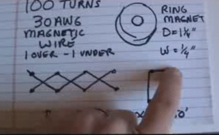
    You can just have 2 pegs per row, and wire this various ways.
    There can be many different ways to do this. I think the wire-crossing
    angle should adhere to the pyramid angle of 51 degrees, 50 min.
    So in other words, you have 2 pegs per row. The distance from one row
    to the next, let us call that X and the distance between pegs, call that Y.
    Pick and X and Y such that tan(51.8333) = X/Y.
    The style I think might be a good one just goes over one, under one,
    over one, under one, creating a diamond shape around the pegs,
    which is a very Walter Russell idea.
    Last edited by morpher44; 01-30-2013, 02:43 AM.

    Leave a comment:


  • Gazzasore
    replied
    And the flower of life
    Attached Files

    Leave a comment:


  • MonsieurM
    replied
    Originally posted by morpher44 View Post
    "Well, Honeycomb, won't ya be my baby, Honeycomb be my own"


    I'm searching for more evidence that this style coil yields a larger
    magnetic field...
    Honeycomb Shape:


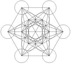
    MetaTron's cube:


    http://en.wikipedia.org/wiki/Metatron's_Cube


    http://en.wikipedia.org/wiki/Saturn's_hexagon

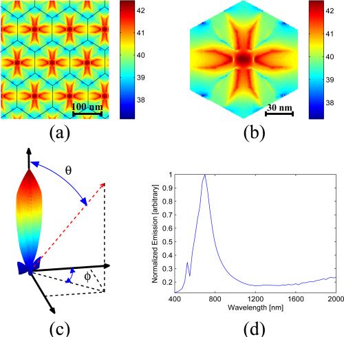
    Optics InfoBase: Optics Express - Unidirectional broadband radiation of honeycomb plasmonic antenna array with broken symmetry


    Last edited by MonsieurM; 01-30-2013, 12:44 AM.

    Leave a comment:


  • morpher44
    replied
    Honeycomb

    "Well, Honeycomb, won't ya be my baby, Honeycomb be my own"

    Do any of you know if a honeycomb coil produces a larger magnetic field
    or not?
    I made a little honeycomb coil, placing 2 rows of 17 equally space
    toothpicks around the "toliet paper roll" 1 5/8 in diameter and wound a 30AWG coil with 100
    turns. The toothpicks are spaced .25 inch apart, to match a
    ring magnet I have.

    With a POT and 2 D-Cells, I can control the amount of current thru the
    coil and then measure the magnetic field with my cell phone.
    current uTeslas Watts
    ----------------------------------
    1E-3 56.23 3E-3
    12.56E-3 57.3 37.68E-3
    80.5E-3 62.34 241.5E-3
    190.2E-3 72.79 570.6E-3
    233.6E-3 80.7 760.8E-3

    I then tried a standard solenoid style coil, 180 turns, much bigger wire,
    longer length... Pumping LARGE amounts of current thru didn't yield
    much at all in terms of magnetic field. Air coils... doh!

    The properties of honeycomb coils are interesting. Btw, I used my
    magic formula to determine how many PEGS to put around
    the circumference ... using PHI and the pyramid angle.
    The shape looks intuitively natural with little wire diamonds
    that look like something nature would create.

    The ring magnet has a north face and a south face, a hole in the
    center, and EAST-WEST are around the circumference.
    So the honeycomb coil would need to be wound as a LARGER
    ring around it -- to cut east-west.

    It occurs to me that if the magnet was on an axis, and possible
    off kilter a bit, that it might spin -- with DC voltages or pulsed DC ...
    not sure.

    To do this with very tiny currents, you will need lots and lots of turns.
    The coil face looks like a pancake coil, but from the side you see
    the wire diamonds.

    I'm searching for more evidence that this style coil yields a larger
    magnetic field...
    Last edited by morpher44; 01-29-2013, 11:53 PM.

    Leave a comment:


  • morpher44
    replied
    photos

    Originally posted by RCGUY View Post
    Ok acording to the schematic C-1 and C-2 500uf caps go directly connected to L1 winding and the caps are placed in the center of the coil windings but in the photo with Hendershots device the transformers are inside the windings, is there a magnetic something happenning in there and possibly the placement of the transformers rotation in the coil is causing a tunning difference of some kind?????
    I feel the 500uf cap in that video is DISINFO and incorrect.
    When you connect it it to L1, you have a tank circuit with a horrible Q
    value that WON'T OSCILLATE. It will just be completely DEAD.
    To prove this is the case, simply connect a scope probe across L1 and CAP,
    as they are connected in parallel. Dial the Volts/Div way way down
    to the most sensitive setting. What do you see? If you see pretty
    much a FLAT-LINE, your patient is dead.
    Get a 6V battery and a Buzzer. Get the buzzer going, and bring
    the coils of the buzzer NEAR L1. See on the scope how well
    it "picks up" the nearby buzzer. You want it to respond and oscillate
    with any nearby oscillating magnetic fields. The big 500uf CAP
    will DRAG that signal down to NOTHING.

    The old picture you must be looking at, and there are several,
    with the transformers IN the coil, may have been just Hendershot
    putting them there to save space on his desk. These 5to1
    transformers can pick up stuff all around them, so by putting
    them here and there nearby other oscillating things, they will
    pick up too with mutual induction. But, there are other photos
    where he had them nicely layed out on the board. So, I would
    bet it doesn't really matter where these are placed.

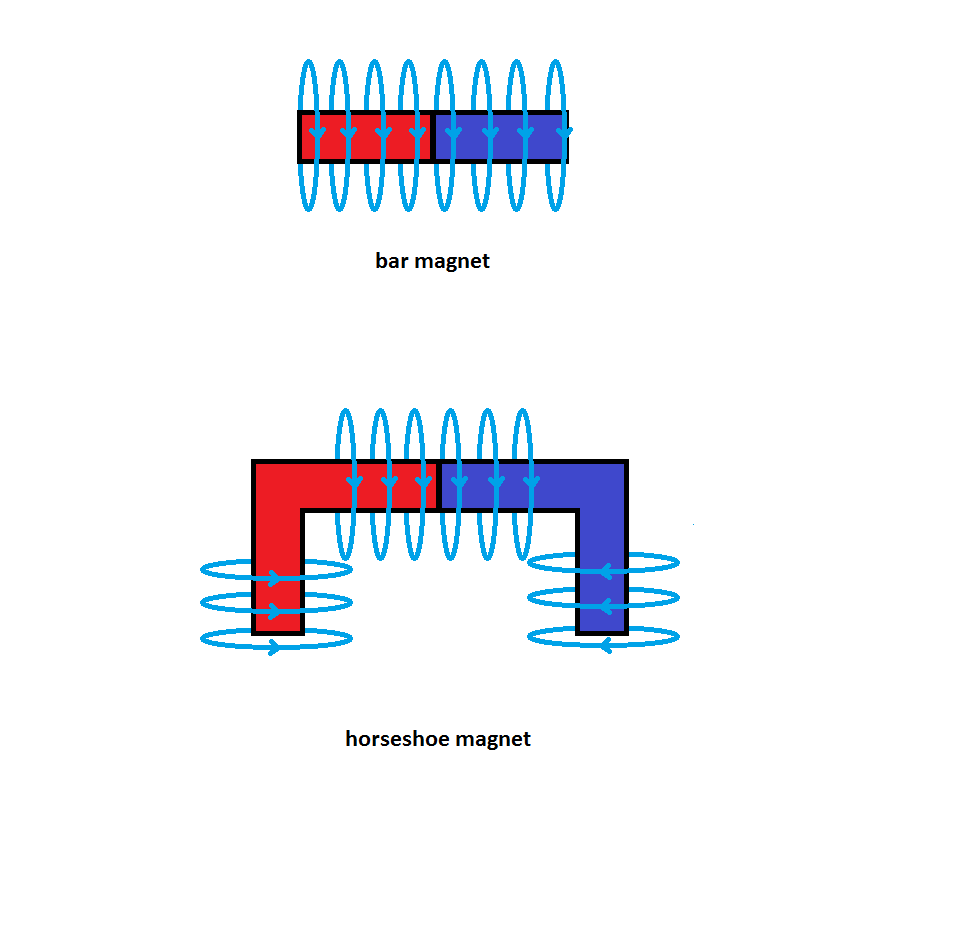
    In my opinion, the more important "mutual induction" that is going
    on is from the bar-magnet-solenoid. With the BAR NEAR
    the magnet, the fields from the horseshoe will spread out
    and follow the bar. One side of the BAR will be energized
    NORTH, and the other SOUTH.
    The solenoid, when pushed near the bar will CUT It's field
    East-West (per Hendershot's discovery), creating a
    magnetic WAKE that sprays out to the LEFT and RIGHT side
    of the bar. I suspect that this spinning WAKE should be SPRAYED
    at our cylinders.

    Do this experiment. Get a bunch hole-punch circular paper pieces
    and dump them on your solid floor near the back side of an open
    door. Standing their holding the door, move it back and forth,
    to half open, then full open, then half open, then full open, etc.
    Observe what the WAKE does to the paper on the floor.
    If done the correct way, you should see them SPIN in the vortex
    you are creating. I think Hendershot's device is doing that,
    but with magnetic fields. If that is true, then the cylinders should
    SIT exactly where the most SPIN is occurring. I've have
    some older videos showing this occur slowed down and using
    compasses, instead of cylinders. I pulse the solenoid at 1 to 2hz
    (slow enough for the compass to respond), and I can make
    the compasses SPIN. I tried this with two different orientations,
    a North-South orientation, and an East-West orientation.
    To my surprise, I could make it work either way, but I had to
    arrange all the components differently. In other words, because
    of the Earth's field, the FOOT-PRINT of everything that is occurring
    to these fields will change. This is easily demonstrated.
    So, I reason that if you put a COIL where I had the compasses,
    the COIL would generate power because it is seeing a
    spinning field (like a virtual spinning magnet inside it).
    Yet, what is wonderful about this approach is there is no friction.
    You don't have to mechanically move these big coils or a big magnet.

    So step 1 might be to not worry about the coils and capacitors so
    much and instead to experiment JUST with the solenoid - bar - magnet.
    You want to make them balanced so that the solenoid exactly
    can match the magnet with the least amount of current.
    With a solenoid, one degree of freedom you have to keep current
    low for the same magnetic field is to increase the number of turns.
    Another is to use a very special metal. Instead of IRON, you could use
    permalloy (k=8000) or mumetal (k=20000). Iron is k=200.
    So in other words, with more expensive solenoids here utilizing
    state-of-the-art metals, you could probably get the solenoid
    to FIGHT the magnet with far less current.
    If you are using steel, that could be bad because steel probably
    has a k far less than IRON ... and hence you would need MORE
    current to fight the magnet. If you choose a really really STRONG
    magnet, you've made your life much harder because the solenoid
    will need to SCALE to your STRONG magnet.

    Magnet - Compass - Solenoids (Hendershot Mystery) - YouTube

    This is good stuff too:
    Hendershot solenoid bar test - YouTube

    See the "first" posts of this thread and read forward. Lots of info.
    Last edited by morpher44; 01-29-2013, 06:51 AM.

    Leave a comment:


  • morpher44
    replied
    give it a try

    Originally posted by RCGUY View Post
    What aboutactually following the video and just doing the way it describes only using the thicker guage wire for the first winding, ok giving that it could be a hoax but has anyone actually tried the schematic as per the video?
    Sure give it a try .. and report back. :-)

    Do NOT, under any circumstances, plug your expensive flat screen TV set
    into your device if you get something going.
    What you are building should be treated with as much respect
    as a high-tension Tesla coil ... if you were to fire the thing up somehow.

    What sort of test equipment do you have?
    Do you have oscilloscope (analog or digital?).
    Do you have pulse generator?
    Good meters for measuring capacitance, inductance, voltage, amps,
    resistance, etc?
    How about a spectrum analyzer?

    These are some of the tools you might need as well to
    understand what is happening and to try various things.

    Leave a comment:


  • morpher44
    replied
    polarized caps

    Originally posted by RCGUY View Post
    What about Non polarized electrolic caps?
    From wikipedia:
    "A non-polarized electrolytic capacitor has both plates anodized so that it can withstand rated voltage in both directions; such capacitors have about half the capacitance per unit volume of polarized capacitors."

    In my personal opinion, you don't want standard electrolytic capacitors.
    You want AC capacitors with a high voltage rating .. such as 450VAC or so.
    Six 40MFD is probably what you need, or you can use
    two 80MFD and two 40MFD. Realize that if you have larger capacitance,
    the magnet-bar-solenoid oscillations will probably be a lot slower.
    This might be BAD in terms of duty-cycle - RMS power.
    People have speculated that Hendershot was trying to achieve 60Hz,
    being a citizen of the United States.

    I have found patents and documentation on a device
    called "Vibrator Power Supply", which is very Hendershot-like, and
    dating from the mid 40s to the mid 50s. You could buy a Tube-like
    device that had a sort of relay thing in it Mallory to make one of these.
    It provide a means to convert 12VDC from your car into
    higher voltage AC to power your TUBE radio in an automobile.
    This tech was no longer needed when transistors became popular.
    Search for "Vibrator Power Supply Design".

    Old-school stuff like this puts us into the mind of a middle-aged
    Hendershot and what he would be exposed to while "inventing"..

    Leave a comment:


  • RCGUY
    replied
    Morpher44

    Ok acording to the schematic C-1 and C-2 500uf caps go directly connected to L1 winding and the caps are placed in the center of the coil windings but in the photo with Hendershots device the transformers are inside the windings, is there a magnetic something happenning in there and possibly the placement of the transformers rotation in the coil is causing a tunning difference of some kind?????

    Leave a comment:

Working...
X