
Torsion....
I'm thinking about Torsion over in the Hendershot thread.
Meanwhile, I found this which is very interesting.
Check out the first experiment and how it resembles the Hubbard coil.
FieldDensity
-

+
the propeller :
Tesla’s Egg of Columbus: Production of working replicas | RT17 | Remarkable Technologies
image from : PHOTO STORY
 Last edited by MonsieurM; 01-09-2013, 06:10 PM.
Leave a comment:
-
Info about Hubbard device
There is plenty of detailed info about Alfred Hubbard device in the book "Awesome Life Force" by Joseph Cater. You can find it in the web:
The Awesome Life Force by Joseph Cater OCred
Please note that the system has many analogies with Clemente Figuera concept for creating induction in the coils.
Also info here:
Hubbard Amplifying transformer
Free Energy Hubbard CoilLast edited by hanon1492; 01-09-2013, 02:31 PM.Leave a comment:
-
indeed , he didOriginally posted by morpher44 View Post ..... and when you look at the ensemble of his patent .... you get this feeling that he left a puzzle for us to figure out
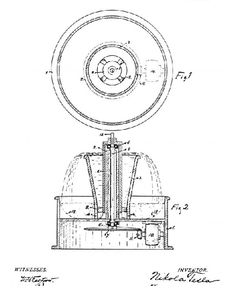
Tesla's Egg of Columbus - YouTubeBack to the "fountain". We have this little tiny tiny spinning propeller thing creating a great big VORTEX in the water. The container for the water is arranged such that the water goes right up to the edge, but doesn't spill over when the thing is OFF. Turn it on, the vortex spins up, the water SHAPE changes due to a BENDING of space and time (from the water's point of view). The water level RAISES, spills over, replenishing the water below, and the circle continues -- in a TOROIDAL movement of water.
Further, we have an example of a "small" amount of input energy creating a LARGE dramatic effect -- lots of water spilling over the edge in great force. Scale this up to a HUGE thing, and the water falling would be impressive.
No laws of thermodynamics have been violated. There is nothing magic here. Its just spinning water and gravity working for you.
Is there an electro-magnetic counter-part to this approach?
Tesla Patent 1,113,716 - Fountain
Water is often used as a way of explaining electrical energy flows.
What geometry do you need to create SPINNING magnetic containers that get ions SPILLING all around the thing??
Leave a comment:
-
tesla's fountain pattent...
Einstein wasn't the only one doing thought experiments.
Tesla was all about that.
So we find Tesla has this funny little "fountain" patent.
This is an ODD one. Here you have a guy who is brilliant with electromagnetic invention creating a patent for what amounts to a little "garden" fountain.
Finding this excited me greatly because I think Tesla's is "teaching" us with some of these patents. He has a legacy that he wants to pass. He has the problem where lots of his patents AREN'T being given or are being secreted away, etc. He wants to be subtle but still be recognized in history (the struggle of being noble and humanitarian versus EGO). So psychologically, how does he deal with these pressures. His form of expression is patents. Some people write. Some people create ART. He invents and gets patents.
Back to the "fountain". We have this little tiny tiny spinning propeller thing creating a great big VORTEX in the water. The container for the water is arranged such that the water goes right up to the edge, but doesn't spill over when the thing is OFF. Turn it on, the vortex spins up, the water SHAPE changes due to a BENDING of space and time (from the water's point of view). The water level RAISES, spills over, replenishing the water below, and the circle continues -- in a TOROIDAL movement of water.
Further, we have an example of a "small" amount of input energy creating a LARGE dramatic effect -- lots of water spilling over the edge in great force. Scale this up to a HUGE thing, and the water falling would be impressive.
No laws of thermodynamics have been violated. There is nothing magic here. Its just spinning water and gravity working for you.
Is there an electro-magnetic counter-part to this approach?
Tesla Patent 1,113,716 - Fountain
Water is often used as a way of explaining electrical energy flows.
What geometry do you need to create SPINNING magnetic containers that get ions SPILLING all around the thing??Last edited by morpher44; 01-08-2013, 10:50 PM.Leave a comment:
-
Morph44 thank you for your enlightening thoughts ... if i may add my little grain of saltOriginally posted by morpher44 View Post
below is the Valvular tube : Nikola Tesla: Disk Turbine / Pump (Articles, patents, links)
and most of his work is Fractal based ....In most of the machinery universally employed for the development, transmission and transformation of mechanical energy, fluid impulses are made to pass, more or less freely, through suitable channels or conduits in one direction while their return is effectively checked or entirely prevented .... this one is one of the most overlooked of his invention ..... think of it as a Wave guide of sort that can be reconfigured geometrically


just a thought + animated picture of the Turbine : http://en.homeconstructor.de/public/...n%202%20HQ.gif
Golden ratio discovered in quantum world: Hidden symmetry observed for the first time in solid state matterLast edited by MonsieurM; 01-08-2013, 09:06 PM.Leave a comment:
-
inverse square law
The magnet just sitting their has I suppose that Torus shaped field around it. As you navigate around the Torus, there are vortex shapes at the N or S pole. At those places, NMR occurs and stuff can SPIN toward the magnet... like a paper clip and its atoms.Originally posted by Dave45 View Post
Whether or not that magnetic field expresses itself PERFECTLY using the PHI ratios for the spiral, I suppose is subject to debate. Certainly we know the inverse-square-law which shows that there is a fall off with distance ... and one would be tempted to use some CONSTANT here. But the math is more likely NOT a constant, but a function, like this:
intensity ~ function(distance,any many other variables, including stuff in the way, etc.) * 1/(distance^2)
In other words, function(distance) needs to take into account the so called NEAR field and FAR field. When NEAR, your experiments work as if function is a constant. Near field stuff is WACKY... Far field is more predictable, except for WEATHER, things in the way, attenuation, etc.
I found this quote: "In this reactive region (NEAR FIELD), not only is an electromagnetic wave being radiated outward into far-space but there is a "reactive" component to the electromagnetic field, meaning that the nature of the field around the antenna is sensitive to, and reacts to, EM absorption in this region (this is not true for absorption far from the antenna, which has no effect on the transmitter or antenna near-field)."
A magnet, I suppose, is a sort of transmitter of fields around it.
A solenoid is more interesting in terms of making the fields OSCILLATE to create effects.Last edited by morpher44; 01-08-2013, 08:51 PM.Leave a comment:
-
ionization...
So one way to create ionization in the immediate area is to have a radioactive material.
Another way, more human friendly, is to have an oscillating magnetic field. As these fields swish back and forth, they excite the ions floating around -- like rubbing a balloon, and CHARGE up the air. As you have these ionic charging going on, your ANTENNA, in the area, does better at receiving.
Ham radio operators know this. They will sometimes CHARGE up their antennas to BOOST gain.
Also, Tesla, while at Colorado Springs had great big JARs filled with salt water. He probably used this material for two purposes; (A) to create salt water capacitors and (B) to allow the salt water to evaporate in the Sun, and ionize the air around his antenna.
-morpher44Last edited by morpher44; 01-08-2013, 07:40 PM.Leave a comment:
-
more thinking out loud...
Suppose Hubbard's original idea was to create a "pickup coil" for background radiation using this PHI ratio "trick".
You could build this thing and see certain results ... and then be encouraged to investigate various ways of optimizing the effects.
Certainly it would be concluded that if you had a better source of radiation, the coil would do better ... which could have pushed Hubbard toward the Radium approach.
It stands to reason, however, that as a "pickup coil", you could optimize it instead to do a better job picking up background radiation, if that were your goal. So in thinking about this, HOW would you get all the background radiation in the immediate area to AIM itself at your little coil?
Answer: A great big magnetic field shaped as a vortex...Leave a comment:
-
is it the magnetic field?
Itsu,Originally posted by Itsu View Post
Thank you very much for doing this experiment.
I had been thinking about this possibility and I have one more "hopeful" idea.
Perhaps the magnetic fields are important here. My reasoning is as follows.
To "push/pull" extra energy in and out of your system, you need NMR effects. You can only get those NMR effects when the magnetic fields get strong enough. Hence, the PHI ratio frequencies expressed as vibrating magnetic fields might yield some sort of negative resistance and/or positive feedback.
Geometry of the fields create may matter as well. Certainly a vortex shape is ideal since particles will SPIN down into the vortex and be attracted to a smaller surface area. You can pick up radiant energy on a simple plate. The problem is ... you need a really really large plate since small plates don't expose enough surface area to get much. But with a magnetic field shaped just right, and I'm betting this conical PHI ratio shape is optimum, the particles can spiral down to a tinier surface area.
That is how I imagine it. It will take some inventive tinkering to prove such a thing.
It is interesting that Otis Car and Walter Russel seemed to want to do things with conical cones. Tesla as well, originally used conical air coils for his device.
The pyramids seem to be expressions in STONE of the inverse-square-law with a CIRCLE (the standing wave on an antenna), squared by the physical pyramid structure.
Yesterday in searching google some more for PHI ratio frequencies, I found some interesting UFO stuff -- such as rumors that UFO audio has been recorded and found to have many PHI ratio harmonics... And other websites where detailed technical information is given discussion PHI ratio harmonics. Harmonics are probably not the correct word -- since PHI is not an integer. Overtone isn't the correct word either. We need a new sort of word for this.
--morpher44Leave a comment:
-
I wonder if a permanent magnet maintains this phi relationship as well.
It only makes sense that the frequency would change as the distance from the magnet increased or decreased.
Leave a comment:
-
Originally posted by morpher44 View Post
Hi Morpher44,
i still have not found the correct sized former for my coils (PHI relation).
But i did a quick setup using a diode to mix 2 PHI (related) frequencies and looking at them with my FFT option (spectrum) of my scope, see diagramm below.
I used 2 Function Generators set at the same output level and at different frequencies (PHI related).
I used both sine waves as square waves.
Frequencies used are:
100Khz and 61.8Khz
100Khz and 161.8Khz
2Mhz and 3.236Mhz
The spectrum clearly showed the both main frequencies and the harmonics.
However, when at or around the PHI relation frequencies, no obvious change in harmonics and/or amplitude levels where noted.
Regards ItsuAttached FilesLeave a comment:
-
-
IRON & other stuff...
Hi Dave,Originally posted by Dave45 View Post
My thoughts exactly. I was thinking of trying things with the air coils FIRST. The PHI relationship, I'm hoping, is what matters here, not the inductance. Magnetic fields in AIR are very FAST, short lived, however, and so it might be difficult to see with my lousy equipment. I have no spectrum analyzer -- shoe string budget.
I know many of you have really good equipment, so I'm hoping to encourage other experimenters with this.
It would be good if we can confirm the PHI ratio beat frequency theory.
Also, in studying one of the pictures from the time, Hubbard appears to be using an 8-cylinder auto distributor and gear box and variac and probably a motor to turn the distributor -- with D.C. motor meter frequency control. Interesting that later in his life he goes on to make a sparc-plug-with-radium pattent -- but never pattents this coil.
So, was he wiring each of the 8 spark plugs (or spark gaps) to each of the 8 outer coils to fire them in turn around a circle? Or was he just creating 8 sparks that were all WIRE-ORed to the same cable. There is a discussion on some other websites about how he didn't have that many wires coming out of his coil. I haven't seen a circuit diagram with the distributor mentioned .. so how he wired things up is a mystery.
I think IRON in the coil doesn't really make sense if using radio signals. You have to SATURATE the iron which will take a bit of current, and so certainly he supplied this device with power -- probably from a battery.
However, I found another story where he connected 4 120 foot wires arranged each going the different directions of the compass. At the center of these 4 wires he connected a glass bulb with mercury -- to create the CHOPPER - make break -- connection to the antenna. This is very radio-ish.
This then went down to his coil. There is some speculation that he had this sort of setup in the woods nearby the LAKE where he powered his boat.
This would be his power transmitter -- unknown to the PRESS -- with a tuned coil. The boat would have a TUNED receiver coil to power the boat.
This article I read gave the impression that this was someones THEORY of what he did -- and provided no evidence. All we have in terms of evidence are the newspaper articles from the time ... which would be good to dig up for a better accurate account.
Certainly there were several aspects of his demonstration that need further explanation.
The achievement, even if radium was inside the coil, is pretty darn amazing.
I think a tiny bit of radium might ionize the coil and make it work better, but I have a feeling there is more to it than just that.
The boat had a 35 horse-power motor ... 26KWatts from a little 14 inch length coil. Yikes!!!
Oh, btw, one way to derive the magic 2.8Ghz number, which is another mystery I would like solved is by adding the 3 diamters:
30 mm + 49 mm + 30 mm
This would represent the total diameter of the coil all taped together.
This wavelength, is approx 2.752Ghz ... round up to 2.8Ghz say.
So this is the size of the fastest possible standing wave across the structure.
The image says "natural magnetic resonance frequency"..
Google searches for "Radium and 2.8" is not easy. APPLE!!! Argh!!!Leave a comment:
-
Morpher44 I think your on the right track bro
watching your work with interest, keep posting
When you add the iron to the system the magic will take place
But building air core is helping to understand
Thanks
daveLeave a comment:
Leave a comment: