
Single wire transmission and the radiant energy principle are different things.
If you are wanting to receive energy from the atmosphere then I don't see how charging metal plates or terminals to high potentials from your own power supply is supposed to be beneficial to the cause.
Energy is meant to flow from high potential to low, so I can't see how one can conclude that a Tesla coil for example will gain energy from the sky or whatever it may be. If the terminal is a higher potential than the surrounding atmosphere then obviously it won't work as one may have hoped. ANY charge on the terminal will have a negative effect. It would be like trying to fill a bucket with free water, but you've already filled it half way from your own supply so it completely defies the point. Not to mention the terminal is directly shorted to ground through the coil so if anything it will essentially just drain energy from the sky to ground.
Tesla's radiant energy patent is based on using an isolated elevated metal plate to charge a condenser, using the potential difference between the earth and the plate, the condenser leaving it an open circuit. The discharging of the condenser requires connecting both terminals of the condenser to a load. But it needs to be switched between charge and discharge in order to work because a short circuit obviously won't allow the condenser to charge, which is where all the other infamous stuff enters the story.
-
dR-Green
So you don't believe in an opportunistic potential force that permeates the space between the ionosphere and the earth? Radiant, Cosmic, Electrostatics, etc are often mentioned by Tesla.
Certainly as frequency changes so does the opportunity. I don't really care what we call it - but your friend Tesla certainly demonstrated the change of nature of different forms of power. So much so that HE termed them distinctly.
Please understand I have no wish to make this complicated in any way, I just want to see the whole picture.
Radiant Energy:Unraveling Tesla’s Greatest Secret by Ken Adachi (June 1, 2001)Leave a comment:
-
Tesla describes that experiment in "The Inventions, Researches, and Writings of Nikola Tesla"Originally posted by DavidE View Post
The Inventions, Researches and Writings of Nikola Tesla, With Special Reference to His Work in Polyphase Currents and High Potential Lighting: Amazon.co.uk: Nikola Tesla, Thomas Commerford Martin: 9781614270607: Books
The same is also described in another experiment, wherein he has a length of wire connected to one terminal of a coil, and observes a bulb lighting and getting dimmer, then lighting again and so on along the length of the wire.
[edit] He connects both terminals of the bulb to the same length of wire, the bulb is essentially short circuited, but depending on where the connections are made along the wire, the bulb lights, or not.[/edit]
The "energised" points related to the wavelength/frequency of operation which set up standing waves along the length of wire that was being used. Tesla doesn't make any references to any ambient energy, or the environment at all for that matter, simply wave propagation and transmission line theory.
Also I'm not sure that it's accurate to say that it's a different form of energy as such. AC at low frequency can kill you, but AC at high frequency apparently does no harm. Why would they be supposed to be different forms of energy? Does a bass singer produce a different form of energy to a soprano singer simply because they sing in different frequency ranges?Last edited by dR-Green; 06-11-2015, 02:51 PM.Leave a comment:
-
dR-Green
If you observe an operating Tesla Hairpin circuit - it appears that the nature of power changes at a certain point (opposite C). Are you saying that at the point of transformation that the energy produced is not from the ambient?


Leave a comment:
-
I would concur with the first part, but not the second. I don't see that ambient energy plays any role whatsoever.Originally posted by Bob Smith View Post
A capacitance AFTER the bulb filament, in my terminology, is in effect loading the terminating end of the transmission line; now the energy is flowing to the terminating capacity via the bulb filament, which happens to be a part of the transmission line, and so it lights.
When the capacitance is removed, the bulb itself becomes the termination, and therefore the energy has no reason to pass through the filament and cause it to light. The transmission line needs some "loading" on the terminating end.
The principle is shown in the Bell Labs video. If the bulb is the termination then the wave will simply reflect back down the transmission line. But you want the energy to flow THROUGH the filament, not reflect off it.Leave a comment:
-
Thanks Dr. Green for the helpful post. Those are excellent demos of single wire transmission. I'd encourage anyone to watch them.Originally posted by dR-Green View Post
As you say, there are varieties of approaches to generating an AC signal that oscillates a primary and secondary at its resonant frequency. Yes, the sig gen is a simple and direct way to achieve this effect. However, there are others, and if we can recognize them as different paths toward achieving the same effect, we should be able to avoid confusion.
To me, both videos demonstrate the interplay of the ambient medium with the resonant HF AC one wire connection to a bulb. The addition of some kind of ground (physical or virtual [antenna]) connection seems to supply what is necessary to complete the circuit so that the bulb lights.
Would you concur?
BobLeave a comment:
-
In my opinion all the "methods" are distractions from the subject. That is to say, there are different methods of achieving the same effect which is one effect, while the different methods are themselves experimental things under development and study. So it will naturally lead to a mess of confusion because there are so many variables involved.Originally posted by Bob Smith View Post
A simple Tesla coil consisting of primary and secondary with an AC source is all you need. Nothing could be simpler. Tune the oscillator to the coil's resonant frequency and you're set up for all your single wire transmission experiments. It's as simple as tuning a radio, because that's essentially what radio is. No fancy oscillators and coils and feedbacks and ferrite rings or a particular type of transistor. Just a signal generator, and amplify signal as desired.
Bulb In Water - Mini Tesla "Test Coil" - YouTube
Also all kinds of transmission mediums work
Tesla Magnifying Transmitter - Colorado Springs Scale Model 1860 kc - Single Wire & Wireless Light - YouTube
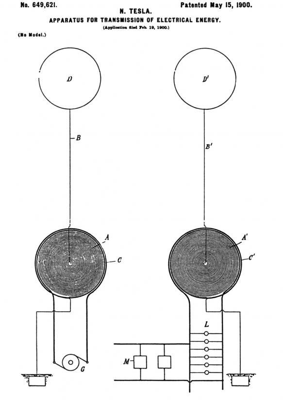
The earth terminal is the (single pole) output.Leave a comment:
-
My Father often told me when I was growing up, "the proof is in the pudding." Ultimately, it is results that speak. And yes, a big part of the problem is that we are perhaps trying to identify a common set of terms, a common language to describe SWP phenomena with fewer concrete examples than theories, which abound.
With enough replicated SWP setups and related effects, we should start to see some kind of consensus around what's being produced, and how it's being done.
I'll post some more examples from online sources; anyone else, please feel free to do so as well.
BobLeave a comment:
-
I think it's no wonder no one understands it. Look at the language used and discussion so far. Quantum this, ambient that, conventional electricity, unconventional. "One-dimensional electricity". What is that??
It's a self-inflicted maze, there's no need for any of it. If I can make stuff that works without knowing any of it, and people who know it don't make stuff that works, then I must conclude that all the extra talk with big words is absolutely useless. But you can sure confuse the beginners through using big irrelevant words! (Isn't that the master plan?)
Your hi-fi will work without the ground connection on the audio input (single wire). The audio signal frequency is sufficiently high. Radio frequency is simply higher still, but otherwise exactly the same principle. You can use your off the shelf audio amplifier to drive your experimental circuits providing they're within the amplifier's frequency range, it's not magic and doesn't need any quantum theories to explain it.
Transmission line theory explains a lot. This video should be mandatory viewing.
AT&T Archives: Similiarities of Wave Behavior (Bonus Edition) - YouTube
It would be advisable to forget everything about Joule Thieves and Slayer circuits and anything else that has been learned on youtube and start from the start. A signal generator, or AC source, and basic (Tesla) coil is all you need. Any transformer for that matter, but it helps to stay on top of the design.
As Carroll already mentioned, ARRL Radio Amateur's Handbook will be most useful here.
More will be learned within 6 months of doing this than 6 years of youtube-ing:
Crystal Radio Initative
Thanks Ernst. Saw pictures of your setup a couple of months ago too I think, it's coming along nicely!Originally posted by Ernst View PostLeave a comment:
-
Most everybody here either is strung up in traditional electrical paradigms, or have adopted their own "speak" about new phenomena and might as well be speaking a foreign language.
That speak satisfies their own egos, but does little to advance the collaborative alternative energy field.
I for one believe that many answers can be found in this SWP subject, but the real exploration for most, is more like an afterthought.
If it can be experimentally proven that ambient power exist, can be collected and transformed to do work - wouldn't that just about change everything?Leave a comment:
-
Hi Ernst
Thanks for your reply and the links. I look forward to reading these docs. Yes, I did see a photo you posted a while back of the TMT you were working on. Pretty exciting stuff. Hope all goes well. Each of us must share in the manner that best fits our circumstances.
I'm not so sure I would share your "difference in potential" assessment of power in the SWP setup as the complete answer. I believe it may indeed be part of the "recipe." However, from my perspective, it is what that difference in potential does to the circuit and surrounding environment, including (and especially) the battery, that fosters a kind of active participation, if you like, by the ambient in the kind of charge made available to the load.
Dr. Green - very enticing photos. I will examine them multiple times to be sure. Photos of this kind are like eye-catching lures in a river of hungry fish. You've got my attention.
Duncan, thanks for your contribution, and I look forward to reviewing the links you kindly shared. Always a pleasure to review the web of interconnected insights in your posts, sir!
BobLeave a comment:
-
Hi Bob,
As I already stated, I do believe that the SWP transmission in some cases relies on the terminal (=antenna) capacity. I have also done a SWP transmission with a coil as receiver, in which case there is a usable voltage generated over the coil. In both of these cases I see no reason to assume additional energy drawn from the surroundings.
I have not done experiments with a hairpin circuit, although I do believe that the SWP transmission with a coil as receiver works on the same principle. Namely that a high frequency signal produces differences of potential over the length of a wire.
You write that your believe is rooted in your experiments and observations. It would be interesting if you can give us some more details. With my experiments in this area the output energy can always be explained by the input power.
Your questions then... Let me first say that I am (still) legally bound not to reveal any more details on my work than I have already done before I got the money to complete my project (=Tesla's Magnifying Transmitter). I hope and trust that these bounds will be released this year. Then I will give you all the details.
This question is largely answered in this article of Tesla of 1932-10-13: "The Eternal Source of Energy of the Universe, Origin and Intensity of Cosmic Rays"How do you understand ambient power?
A friend of mine has recently published his theory (here) which gives it a more (modern) scientific foundation.
There is slightly more to it which you can read in Tesla's article of June 1900: "The problem of increasing human energy". The part where he describes the self acting machine. You will LOVE that article once you know how to read it. Part of it is explained here.
To some extend. I am still working on the final proof, which I hope to get very soon.Has any of your experimental work revealed anything to you about the nature and working of ambient power?
As I said my answer here will probably disappoint you, but I can talk freely about SWP
@dR-Green: Great work! Those coils look familiar!

Ernst.Leave a comment:
-
-
Hi ErnstOriginally posted by Ernst View Post
I believe ambient power plays a role in SWP transmission because of my own observations and tests. If you look at the setup of the single wire transmission, there is one leg left open as an antenna. I do not believe the effect is capacitive; I believe it is drawing in ambient charge.
I believe, along with others, that the hairpin circuit also draws in ambient charge in order to light bulbs with a single wire. Because the hairpin circuit deals with higher voltage, the bulb functions as its own antenna to draw in ambient charge.
A couple of friendly questions to further the discussion:
How do you understand ambient power? Has any of your experimental work revealed anything to you about the nature and working of ambient power?
Respectfully,
BobLeave a comment:
-
Hi Bob a very interesting subject and like others I am pretty convinced elements of the longtitudinal wave are being brought to the fore I add these investigations for your interest
first the demonstration done by JNL Labs
Avramenko's Free Electrons Pump v1.0 by Jean-Louis Naudin
It seems JNL did some later 'improvements' to this design and came up with this demonstration
The AFEP v1.2, Single-Wire Energy transmission test by Jean-Louis Naudin
The circuit drawn in the first article of this PDF
http://www.free-energy-info.com/Issue13.pdf
is suggested as an improvement on the basic AV plug for single wire conversion.
The useful comment on neons as longitudinal wave detectors posted earlier reminded me of this now ancient circuit and information which obviously supports the idea. using neons teetering on the edge (so to speak)

The schematic, is a derivative of a microwave detector
described in the February, 1980, "Ham Radio" magazine. As
originally created, the circuit's purpose is to detect microwave RF
standing waves, but with minor modification, it can also be used as
an effective scalar wave detector.
The schematic shows a round magnet epoxied to the NE-2 lamp, to help
isolate it from EM signals. Additionally, the circuit should be
enclosed in a metal box, or "Faraday Cage", with shielded I/O
connectors.
The power source consists of eight 9V batteries. Battery life is
very nearly the same as shelf life, because the lamp is operated in
"starvation" mode, drawing approximately 0.1ma.
The 25K and 250K potentiometers are adjusted first to fire the NE-2,
at approximately 60-70 volts, then adjusted until only the tip of
the cathode electrode glows. The 100K pot is adjusted for optimum
output gain.
Notes:
1. The 741 can be replaced with a 1458 cascade amplifier for
better results.
2. The RF loops in the NE-2 leads are mandatory to reduce
interference as well as lamp current noise.
3. Component values are not critical, and can be changed as
required for the type of output device.
4. Removing the magnet and Faraday Cage, and adding a
capacitively coupled loop antenna will permit use as a
microwave EM detector.
Kind regards Duncan
Leave a comment:


Leave a comment: