
This forum is preserved as a permanent archive. The community continues at eMedia Press.

Announcement

Collapse
No announcement yet.

Cr�me de la cr�me (perhaps)

Collapse
X
 
  • Filter
  • Time
  • Show
Clear All
new posts

  • #61
    Two good posts Duncan ... you make me smile !

    I would not be so flippant as to call you Dr Duncan because I think it possible you would be offended at such title which reveals acceptance of 'knowledge' and 'theory' you are so clearly now well past accepting - the same as which students are still required to believe as they continue to be 'educated' as if parrots.

    I don't wish to be picky, but you keep saying that Longitudinal Radiation is with respect to Ground, but of course the radiation is generated with respect to a Radiating Ground, and that need not necessarily be Earth.

    Indeed the outcomes (potentially devastating at much higher frequencies) of PTB weaponised longitudinal radiation inclusions within portable, craft based and space related technologies has already been witnessed via worldwide TV, for PTB 'requirements' are quite different to those we ordinary citizens would deem as being essential.

    Cheers .......... Graham
    Last edited by GSM; 01-12-2014, 10:05 AM.

    Comment


    • #62
      Originally posted by dR-Green
      I'm not talking about wave propagation. Here you are misleading yourself again, you are arguing against what you think I'm talking about, not what I'm actually talking about.

      An impulse wave is not a square wave. Read Steinmetz.


      You speak to me of basic radio theory, when you reject all basic radio principles and dispatch those who explain such things as basic LC resonance because it's "conventional nonsense" to the point that they remove their posts? Nice. How non-hypocritical.

      You should check the Eric Dollard thread once in a while, then you might realise that I've actually got a WORKING Colorado Springs scale model transmitter and receiver set built with Eric's personal assistance and I'm not getting all my information from google or watching videos of what other people have done. I don't want to be "saved", thank you very much.
      Whatever you can do,or dream you can,begin it.Boldness has genius,power and magic in it.Begin it now.

      Comment


      • #63
        Originally posted by GSM View Post
        Two good posts Duncan ... you make me smile !

        I would not be so flippant as to call you Dr Duncan because I think it possible you would be offended at such title which reveals acceptance of 'knowledge' and 'theory' you are so clearly now well past accepting - the same as which students are still required to believe as they continue to be 'educated' as if parrots.

        I don't wish to be picky, but you keep saying that Longitudinal Radiation is with respect to Ground, but of course the radiation is generated with respect to a Radiating Ground, and that need not necessarily be Earth.

        Indeed the outcomes (potentially devastating at much higher frequencies) of PTB weaponised longitudinal radiation inclusions within portable, craft based and space related technologies has already been witnessed via worldwide TV, for PTB 'requirements' are quite different to those we ordinary citizens would deem as being essential.

        Cheers .......... Graham
        Whatever you can do,or dream you can,begin it.Boldness has genius,power and magic in it.Begin it now.

        Comment


        • #64
          No more coil winding

          Here's to THAT!!!

          Dave

          Comment


          • #65
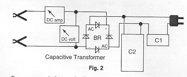
            Hey Duncan, I decided to play around with this basic circuit because I've got a very expensive Optima 12V LA battery I got in a yard sale but never have been able to get a good charge on it. I discovered some very good things along the way of playing with this setup. I started out using your basic schematic above with a heavy toroid 120VAC to 24VAC transformer that can provide a lot of current. I tried AC caps from 3.5 uf to 62 uf and was having some luck charging but the power factor was always up around 0.70. Watts were fairly low from about 2.8 to 5 watts and charging was quite slow as monitored with a Fluke DC meter.

            Then I decided to look at George Wiseman's capacitive charging circuit and what a huge difference that made when I hooked it up as I will describe below. Power factor dropped to 0.02 and watts consumed were around 1.9 watts while the battery was charging way faster as observed on the meter. Before trying his circuit I also tried 120VAC with a 1:1 transformer feeding the setup you posted but charging was slow and PF high with that. But when I went to the circuit below charging got very fast and PF very very low as I said. I've had this info for a while but never really looked into it and especially with a watt meter / PF meter attached. In my setup I used a 220VAC 62 uf cap for C2 and a 14uf 120VAC cap for C1. Based on his formula of input voltage divided by C2 over C1 my output charging voltage is around 27.1 volts. I'll have to check it with the voltmeter to see if that's correct. This setup also limits current based on what cap values are used. Thanks for bringing this up!
            Attached Files
            Last edited by ewizard; 01-12-2014, 09:38 PM.
            There is no important work, there are only a series of moments to demonstrate your mastery and impeccability. Quote from Almine

            Comment


            • #66
              Originally posted by ewizard View Post
              Hey Duncan, I decided to play around with this basic circuit because I've got a very expensive Optima 12V LA battery I got in a yard sale but never have been able to get a good charge on it. I discovered some very good things along the way of playing with this setup. I started out using your basic schematic above with a heavy toroid 120VAC to 24VAC transformer that can provide a lot of current. I tried AC caps from 3.5 uf to 62 uf and was having some luck charging but the power factor was always up around 0.70. Watts were fairly low from about 2.8 to 5 watts and charging was quite slow as monitored with a Fluke DC meter.

              Then I decided to look at George Wiseman's capacitive charging circuit and what a huge difference that made when I hooked it up as I will describe below. Power factor dropped to 0.02 and watts consumed were around 1.9 watts while the battery was charging way faster as observed on the meter. Before trying his circuit I also tried 120VAC with a 1:1 transformer feeding the setup you posted but charging was slow and PF high with that. But when I went to the circuit below charging got very fast and PF very very low as I said. I've had this info for a while but never really looked into it and especially with a watt meter / PF meter attached. In my setup I used a 220VAC 62 uf cap for C2 and a 14uf 120VAC cap for C1. Based on his formula of input voltage divided by C2 over C1 my output charging voltage is around 27.1 volts. I'll have to check it with the voltmeter to see if that's correct. This setup also limits current based on what cap values are used. Thanks for bringing this up!
              Thanks ewizard I was aware of Wisemans work but of course LA batteries have been charged like that before there was a USA never mind a George Wiseman. I didn't think it a particularly good example to offer folks not au fait with exposed high voltages and charged capacitors I could have cited Tom Dick or Harry as regards the implication its hundreds of years old technology.
              Here's yet another Tom or more probably a 'big Dick' in this example charging huge banks of batteries in minuets , and rejuvenating batteries that have been sulphated for years very quickly.

              Capacitive Battery Charger - John Saves Energy"well we know what they want. They want more for themselves and less for every body else"

              George Carlin ~ The American Dream - YouTubeI know full well there are strange thing happening when an LA battery is being charged !! I got a serious ear bashing from my wife, when after a couple of days charging a battery on one of our Granite work surfaces, upon moving the battery the Granite had taken on the shape of the cell structure within !! And despite a whole day of re polishing there is still the faint outline !!

              I wonder if your now prepared to make an educated guess at why Grumage had to spend days polishing and scraping ?poor o'l Grum
              Last edited by Duncan; 01-13-2014, 06:40 AM.
              Whatever you can do,or dream you can,begin it.Boldness has genius,power and magic in it.Begin it now.

              Comment


              • #67
                Well Duncan

                I will take a stab at your question, mainly, because I want you to continue, and for some reason, you always stop, never to finish, and I'm never sure why. I'm not answering because I really know what your getting at, so go easy.
                First, I assume your granite was raised, ridges, and not just a stain?

                So, once upon a time, cells were placed in wooden boxes, which didn't work well.
                Edison used metal box. The metal box would discharge to ground, not good. So now we use plastic, insulator, and it should not matter if you put your battery on the cement floor.

                So if you are getting ridges in the granite, then we have an ion flow, so we either have a magnetic field attracting ions, should probably say, inductive or dielectric field causing ion migration.

                Machine

                Comment


                • #68
                  I've build myself a capacitive charger to see if that really can desulfate lead acid battery. I have one which were sitting on 0 volts and after connected to normal charger can only take miliamps.

                  Comment


                  • #69
                    Originally posted by boguslaw View Post
                    I've build myself a capacitive charger to see if that really can desulfate lead acid battery. I have one which were sitting on 0 volts and after connected to normal charger can only take miliamps.
                    Hi Boguslaw,

                    Just remember , if the lead acid battery plates are shorted out (the internal lead plates)-which is the cause of 30% percent of most dead batteries, then no matter what kind of charger you put on it. Will be a waste of time -"no worky"

                    Regards,
                    Paul

                    Comment


                    • #70
                      Originally posted by boguslaw View Post
                      I've build myself a capacitive charger to see if that really can desulfate lead acid battery. I have one which were sitting on 0 volts and after connected to normal charger can only take miliamps.
                      just keep a very close eye on it boguslaw , and do it slow, I have brought a few back from the grave. I only posted on the subject really to point out that the impossible is being done . that is reactive current is doing useful work its as simple as that, if your battery charges at all from that method the laws of AC theory have just been broken. Its then a case of making it very much better! Its Scary and not very safe like wiseman and John suggest still prove to yourself (and us of course) good luck
                      PS .. I have PM'd you regarding
                      Last edited by Duncan; 01-19-2014, 12:28 AM.
                      Whatever you can do,or dream you can,begin it.Boldness has genius,power and magic in it.Begin it now.

                      Comment


                      • #71
                        It seems logical to me that the next step along the line from these crude capacitive chargers which I really only posted as proof of concept. Is to do it very much faster using a fraction of the power and discover a way of tracking and holding series resonance , here are a few previous articles from guys who haven't quite hit the bulls eye but have got close.


                        meanwhile being but a simple soul I was wondering if something might be made of this idea I had
                        as yet untried ..


                        which in turn I stole from here

                        Simple DIY Induction Heater - RMCybernetics

                        you will see the circuit is supposed to automatically track and hold resonance , what chance guys ? Is it worth a try? I'm sure it can't be that simple someone would have done it !
                        PS not at all sure a load is a good Idea, it being effectively a tuned circuit it would effect the Q factor already low because of very low Internal resistance of a LA battery
                        Last edited by Duncan; 01-19-2014, 04:28 AM.
                        Whatever you can do,or dream you can,begin it.Boldness has genius,power and magic in it.Begin it now.

                        Comment


                        • #72
                          Originally posted by Duncan View Post
                          It seems logical to me that the next step along the line from these crude capacitive chargers which I really only posted as proof of concept. Is to do it very much faster using a fraction of the power and discover a way of tracking and holding series resonance , here are a few previous articles from guys who haven't quite hit the bulls eye but have got close.


                          meanwhile being but a simple soul I was wondering if something might be made of this idea I had
                          as yet untried ..


                          which in turn I stole from here

                          Simple DIY Induction Heater - RMCybernetics

                          you will see the circuit is supposed to automatically track and hold resonance , what chance guys ? Is it worth a try? I'm sure it can't be that simple someone would have done it !
                          PS not at all sure a load is a good Idea, it being effectively a tuned circuit it would effect the Q factor already low because of very low Internal resistance of a LA battery
                          I built that first one ( http://dnp.s3.amazonaws.com/b/b6/201...desulfator.pdf ) a year or two ago. It was that exact circuit from that PDF (12V) and it works fairly well. I used all the correct parts as specified but I do think I might have undersized one of the inductors a bit and it would probably be best to have a slightly larger L1 inductor. IIRC looking at it on a scope the pulses looked a bit weak. It's on the back burner as one of those projects to look at again and do a bit of tweaking on.
                          There is no important work, there are only a series of moments to demonstrate your mastery and impeccability. Quote from Almine

                          Comment


                          • #73
                            Hi ewizard thanks for your circuit and observations, Its important to realise I have been chasing this rabbit a long time! Focusing on battery resonance is if you like the end of six or seven entirely different investigations.
                            One on the mathematics of crystal oscillators, another on the temporary phenomenal energy available from the three battery generating system on this forum. Which in turn IMHO depends on the LA battery being held at resonance.
                            With these pulse chargers and of course the Bedini SSGs they all have in common the LA battery
                            is at series resonance at some stage.
                            My belief then is that if series resonance can be found and held on the battery despite rapidly changing conditions then the battery would remain fully charged.
                            I introduced these resonant chargers just to stress the importance of resonance. Strange how we all talk of de sulphating a battery as so much hum drum these days, folks need to take a deep breath,and remind themselves they are doing something considered impossible.
                            Just adding to that ewiz none of these resonance chargers are actually anywhere near resonance
                            when we discover a way to track it and stay tuned then I think you'll see the feathers fly!
                            Whatever you can do,or dream you can,begin it.Boldness has genius,power and magic in it.Begin it now.

                            Comment


                            • #74
                              20 Kilowatt Self Running

                              My circuit? That was your circuit - first one in your post above - lol anyway just wanted to mention I built it. Now here is something a bit more interesting. I got this from a scanned PDF member 'wings' posted at OU - Quest for Zero Point by Moray King. Very good book. From pages 78-80 (or 39-40 if you are using the PDF viewer page count) this info I found very interesting and I think relevant to some discussion here. Apologies for below text may not be perfect as it was OCR'd and then quickly corrected some errors.

                              " Pappas (1991)hypothesized all sparks produce excessive energy. Shoulders (1991) demonstrated that excessive energy can be created in any electrical discharge that produces EV's. What if every spark naturally produces submicron plasmoids (even smaller than Shoulder's EV 's)? Finally, there is abrupt ion motion on the inception of any spark, fulfilling Moray's hypothesis. There is a strong likelihood of some ZPE coupling in any abrupt electrical discharge. In fact some investigators have proposed that an abrupt voltage pulse with only (vacuum) displacement current and minimal charge motion is sufficient to produce anomalously excessive energy. Bearden (1993) proposed this is his "final secret, and Hyde (1990) used this principle in designing his invention (a mechanical electrostatic field chopper) that reportedly output 20 KW while self running. Hyde stressed there should be no corona present whatsoever. The Swiss ML Converter could likewise be sirnply explained if indeed there were energy in all electrostatic pulses.
                              Electrostatic pulses or abrupt voltage spikes are notoriously difficult to tap efficiently as an energy source.

                              Many inventors have directed high voltage pulses to recharge batteries with claims of over unity. Unfortunately such pulsing often damages the battery, and of course, an energy machine that cannot self run, but instead relies on batteries, is unconvincing to skeptics.
                              Clearly what is needed is a method to convert voltage spikes to a useful form of power, preferably DC. Hyde (1990) had to solve this problem in order to make his machine free running. His solution (described in figure 6 of his patent, also King, 1993) took advantage of the fact that even though the individual electrostatic pulses were of high voltage, the current (and thus power) of each was very low. This allowed Hyde to make a voltage divider current multiplier circuit utilizing a large number of inexpensive capacitors and diodes that could be run in excess of their voltage specification without damage. High voltage electrostatic pulses were converted to amplified current pulses at a lower voltage which were then rectified to DC by Standard means. Hyde empirically solved a difficult engineering problem, and the solution allowed him to build a self running energy machine. An easy to build, efficient, current multiplier would facilitate wide spread experiments to investigate claims of excessive energy in electrostatic pulses or sparks, as well as form the basis for a solid state zero-point energy machine. The following Pulse Current Multiplier (PCM) was inspired by Hyde's invention. The PCM is based on the Standard
                              voltage division technique of charging a bank of capacitors in series,
                              then discharging them in parallel. Figure 3 illustrates four stages of the
                              PCM. In practice it is desirable to have ten or more stages. The high
                              voltage pulse is input across the A terminals at the polarity shown.

                              The sharper the voltage spike, the better the performance.
                              The inductances should be the minimum value necessary to block the
                              input, for they must allow the output current (as a slow rise time pulse)
                              to pass with minimal attenuation. Hyde did not show any blocking
                              inductances in his patent. Since he developed his circuit empirically,
                              perhaps long or coiled output wires provided a sufficient blocking in-
                              ductance to achieve the same behavior. Ferrite beads might also suffice.
                              Since the PCM uses inexpensive components, it offers an economical
                              investigation of a possible ZPE coherence associated with high voltage
                              pulses and discharges.

                              A ten stage PCM amplifies the current by a factor of ten. Two
                              such PCM's can be combined in series to create a multiplication factor
                              of 100 (Figure 4). The output from the first PCM is impressed across the
                              input of the second. Since the pulses entering the second PCM will not
                              be as sharp, larger blocking inductances will be required in it. The principle
                              can be extended to a third PCM in series to give a multiplication
                              factor of 1000. Thus a sharp 40 KV spike could be stepped down to a
                              less steep 4 KV pulse and then to a wider 400 volt pulse. The second and third PCM 's will require more robust circuit components since
                              appreciable current is being accumulated. Once the pulses become sufficiently wide, then Standard, solid state switching technology can be used instead of the blocking inductances to create a PCM via Standard electrical engineering, voltage division techniques. Such a PCM could be
                              employed last in the series. An appropriate configuration of PCM's can
                              thus become an efficient voltage spike Converter.
                              output current pulse occurs across the B terminals. The inductors' purpose
                              is to block the sharp input voltage pulse (via high impedance) and
                              channel it down the (low impedance) series path which should be physically short.
                              Last edited by ewizard; 01-20-2014, 06:39 PM.
                              There is no important work, there are only a series of moments to demonstrate your mastery and impeccability. Quote from Almine

                              Comment


                              • #75
                                I'm a fan of Pappas Ewiz particularly this piece of work where he substitutes Amperes force law for the Lorentz /Einstein force law with very different results , It takes a bit to try and spit the pips out of that!

                                http://papimi.gr/university.htm

                                thank you very much for this contribution.
                                Last edited by Duncan; 01-21-2014, 07:48 AM.
                                Whatever you can do,or dream you can,begin it.Boldness has genius,power and magic in it.Begin it now.

                                Comment

                                Working...
                                X