This forum is preserved as a permanent archive. The community continues at eMedia Press.

Announcement

Collapse
No announcement yet.

Re-Inventing The Wheel-Part1-Clemente_Figuera

Collapse
X
 
  • Filter
  • Time
  • Show
Clear All
new posts

  • hanon1492
    replied
    This is posted in the other forum

    Originally posted by marathonman View Post

    can you believe the statement was made that Buforn neither uses any internal energy recycling device. Wow ! talk about brain dead, i guess that power is brought into the system from the power fairies. ha, ha, ha !
    i must of laughed for 30 min. total incomprehention at it's finest.

    TRUST ME FOLKS when i say the power is recycled back and forth between the primaries and part G every half turn it does exactly that. THIS IS THE KEY to self sustainment otherwise it is no better than a transformer.

    MM
    Then you have been lying all around with your COP 3 device made with resistors

    For references to my post which was just stating what is written in the patent. Not your own opinion which is what you write in your posts. You are just promoting the toroid and you are just distorting what the patent states.


    Evidences of that:

    - You said that was done with resistors. Now you say that resistors wont work and just the toroid works because if not it is just a transformer.... Are you scamming people?

    - You sold your 100 W in / 300 W output device. A very smart move: selling your only ou device forthe price of an iron core.

    - No pictures taken, nor videos of your device

    - I suppose no witnesses from this planet

    - Your notebook got spoiled by a flooding in your area. Now you dont have nor the device neither your notes...

    - For one device you released two sets of design parameters, one in OU dot com and other in EF dot com with different cores sizes, turns and driving parameters. How can that be possible?

    - Now someone has stolen in your home and they took your camera cable you can not show your progress in part G. BTW when will you get a new cable? Two weeks all your followers waiting for those pictures.

    - Now you have put up a funding campaing to give you money . OMG

    - In a communication you told me that you PCB was costing around 350 dollars, telling me that you havent that money. I see now that the one you bought was just 33 dollars...

    You are confusing people saying that just the toroid invented by your mentor, not by you is the only method which work. This is your opinion. The key is to move the two fields no matter how you do it. How many OU devices have an internal recycling device? None. Even Figuera has none. Just your own proposal has one.

    You are distorting what the patent says. That why you get mad each time that I just quote the patent. If the toroid was essential then it must be described in the patent. But it is not even mentioned. If you dont describe an essential part then your patent is invalid. Period. Dont fool people to believe that the toroid is mandatory when it is not.

    I am about posting my builder pictures in the other thread and start to ask just technical questions about the alleged recycling concept. Just technical question and wait for the technical answers.
    Last edited by hanon1492; 11-05-2016, 12:20 PM.

    Leave a comment:


  • seaad
    replied
    ""The details releases in the latest 1914 patent by Buforn invalidate your proposal and reinforce the use of straight cores.""

    I was thinking of that also when I made my proposal.
    Gaps "mostly" reduces the power factor, but not always. As in my ' 100%+ test' with space between primary coils and inner rod with secondary.

    Follow your path as you wish, that was only a suggestion.
    I do not care how to make OU the only main thing is to make it!

    Regards / Arne
    Last edited by seaad; 11-04-2016, 02:02 PM.

    Leave a comment:


  • hanon1492
    replied
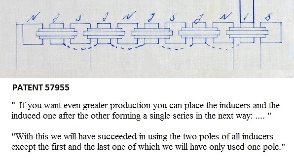
    The details releases in the latest 1914 patent by Buforn invalidate your proposal and reinforce the use of straight cores.

    I always tend to follow the patents guidelines.

    I agree with Ufo that probably the three cores are separated by a small gap or an insulator/aislant. Maybe just to define the permanent location of the electromagnets poles, which act as permanent exciter elements and they must not be "mixed up" with the induction achieved in the induced coil, which is changing polarity in each half cycle. I already posted that months ago.


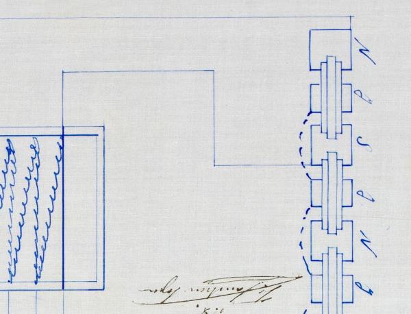
    Note that Buforn neither uses any internal energy recycling device..: He just uses a fraction of the energy output to excite the electromagnets continuously. This is what is written in the patents. The rest are just our interpretations.

    Another advantage is that in the sinus of the core of the induced electromagnets we can put another small size induced electromagnet with equal or greater core length than the large induced one. In these second group of induced an electric current will be produced, as in the first group of induced, and this produced current will be sufficient for the consumption in the continuous excitation of the machine, being completely free all the other current produced by the first induced electromagnets in order to use it in all purposes you want.

    Leave a comment:


  • seaad
    replied
    HOPE and Suggestion

    In post 1525 hanon send me (us) a video; This what happens with two fields in repulsion when moving the fields https://vimeo.com/155371838

    That video shows one principle to produce voltage.
    Another principle can be seen in my picture below; 'Fig Induction'
    From that (x) principle I have made a suggestion of a Figuera scenario, se my picture; 'Figuera Principle 1'

    In this picture the green and blue rectangels are representing the Figuera N and S coils. Here they are used as modulating coils, weakening and strengthen the magnetic flux from the permanent magnets making movement, Orange arrows, of the magnetic fluxlines, Violet lines.
    No DC power needed!!
    Now induction occurs in the y-coil, BUT the fluxlines from that, Red arrows goes perpendicular to the incomming modulated fluxlines! And that is my hope to produce power without disturbing the primary coils.
    (Don't kill the dipole!)

    Regards /Arne
    Attached Files
    Last edited by seaad; 11-04-2016, 12:13 PM.

    Leave a comment:


  • seaad
    replied
    Reply 2

    --> hanon, All, (not MM, UFOp)

    A new picture showing the difference of magnetism from test with DC OR signals containing DC above zero level at poles between N-y-S when operating in normal or bucking mode.

    N-N or S-S at normal mode
    N-S or S-N at bucking mode

    Here comes my always bad answer ; In normal mode WITH OUTPUT = YES the sad thing is that we have back-kick affecting the primaries. The magnetism reflects back from y to S+N (magnetic coupling).

    PS: And worse! We have to add the DC-power keeping the AC above zero.level !!

    Arne
    Attached Files
    Last edited by seaad; 11-05-2016, 05:17 PM.

    Leave a comment:


  • Ufopolitics
    replied
    Originally posted by marathonman View Post
    UFOP;

    I would not waist one second more of breath on this approach to insanity. let them be, let them waste all they're time and effort to the point of giving up. then and only then will they decide if what i have been bringing to the table is a reasonable,viable alternative to they're insanity approach.

    good luck seaad, all, but unfortunately even lady luck won't be by your side.

    off toppic post can kill a thread. look at OU..... dead as hell.

    MM
    MM,

    You're right!

    It would be just like trying to teach a deaf and blind person...where no matters how state of the art Audio-Visuals are utilized...nothing at ALL would be captured...

    It is a shame though, honestly.

    I've got a LOT to do and MAKE...to waste time here...


    Au revoir...


    Ufopolitics
    Last edited by Ufopolitics; 11-03-2016, 02:44 PM.

    Leave a comment:


  • marathonman
    replied
    Breath

    UFOP;

    I would not waist one second more of breath on this approach to insanity. let them be, let them waste all they're time and effort to the point of giving up. then and only then will they decide if what i have been bringing to the table is a reasonable,viable alternative to they're insanity approach.

    good luck seaad, all, but unfortunately even lady luck won't be by your side.

    off toppic post can kill a thread. look at OU..... dead as hell.

    MM
    Last edited by marathonman; 11-03-2016, 02:26 PM.

    Leave a comment:


  • vidbid
    replied
    Originally posted by gyula View Post
    yes, here they are for instance at the European Patent Office, they also have free machine translating service if you click on the "Description" menu point on the left column:
    1) https://worldwide.espacenet.com/publ...0243635A&KC=A#
    2) https://worldwide.espacenet.com/publ...1150938A&KC=A#

    Gyula

    PS for qwekw: thanks for your post above with the patent details.
    Thank you, Gyula, for posting those.

    Much appreciated.

    Leave a comment:


  • Ufopolitics
    replied
    Originally posted by seaad View Post
    --> UFO #1529
    Please land your UFO and calm down!
    This was a fundamental test normal/ bucking. I responded to hanon proposal #1510 and told my results only. /saeed
    Little Ant,


    If I land my UFO...you must run and hide...or would be blown away or be abducted (meant crispy burnt for an Ant) under the high antigravity beam...

    Now I went to Hanon Post #1510

    Plus I will quote it here:

    Originally posted by hanon1492 View Post
    This is an explanation for the Figuera generator. A motionless generator creating virtual motion by moving two opposing repulsive magnetic fields in unison.

    https://vimeo.com/155371840

    No motion = No dragging

    No dragging = No need for the equivalence of mechanical work to electricity


    For further details just read and study the patent filed in 1908.

    And, yes, I watched video (many times)

    Now, could You tell me where he "proposes" to use a single core?

    Plus sticking Core like four times out of primaries?

    Plus using MilliVolts and Milli Amps to drive Primaries?


    The more I read...the less I can find this "Hanon Proposal" that you are referring to...and have tested?...

    Please "Enlighten Me"...


    Ufopolitics

    Edit 1...btw, you signed Saeed?...is it Seaad or is it Saeed...?...which one should be used?
    Last edited by Ufopolitics; 11-03-2016, 01:54 PM.

    Leave a comment:


  • seaad
    replied
    --> UFO #1529
    Please land your UFO and calm down!
    This was a fundamental test normal/ bucking. I responded to hanon proposal #1510 and told my results only. /seaad
    Last edited by seaad; 11-03-2016, 08:23 PM.

    Leave a comment:


  • Ufopolitics
    replied
    Originally posted by hanon1492 View Post
    BTW, this is one of my test devices


    Two set of three identical coils. 90 mm diameter and 50 mm thickness. 300 turns. Wire 1 mm diameter.

    I will not share any further pictures because all it is represented in the previous one. I already posted some pics and results in OU dot com forum some months ago.

    This is just to show that there are more builders than those who proclaims themselves as builders, one of them without even showing yet any picture of a coil.

    Hanon,

    Please allow me...just some Constructive Criticism...

    Your Primaries...can't they be ANY FLATTER?...I mean, by now they look like Flying Discs?

    Your Ratio of Thickness Versus Length...should be like 3 Diameter X 0.5 Length...

    Do you realize the HUGE SPATIAL MAGNETIC FIELD LOSSES BETWEEN THEIR OWN POLES you are having there...just between those Two Primaries shown above?

    The Ratio of a well designed Electromagnet should be anywhere around 3 Units of Length X 1 Unit Thickness...

    And so it means that The Further Apart the Poles are...the much less "SELF LEAKAGE" Magnetic Field would suffer...

    I honestly doubt...you will have any good results there...


    Sincerely


    Ufopolitics
    Last edited by Ufopolitics; 11-03-2016, 12:57 PM.

    Leave a comment:


  • seaad
    replied
    LT spice XVII (+ plus)

    Here you can see the relationship between DC and AC-signals.
    To improve the efficiency and output power two G-parts (not closed wiring) have been used! /Arne
    Attached Files
    Last edited by seaad; 11-03-2016, 12:47 PM.

    Leave a comment:


  • Ufopolitics
    replied
    Ant Brain...

    Originally posted by seaad View Post
    --> hanon, All


    Hello! I have made some tests again, in our real world, to check the above statement and more.

    Test set up according to picture 'Figuera 1 D' and 'CIMG1447' below.

    (I have assumed that the middle coil (y) (dotted points) in the hanon 'film' is a normal helix coil)


    1) Normal transformer N-y-S coils: NS-y-NS OUTPUT: ~ 0.5 Volt

    2) Normal transformer with DC input making AC go above zero N-y-S coils: NS-y-NS OUTPUT: ~ 0.5 Volt

    3)Bucked transformer (as the hanon "film") N-y-S coils: SN-y-NS OUTPUT: ~ 2 milli Volt

    4)Bucked transformer with DC input making AC go above zero (as the hanon "film") N-y-S coils: SN-y-NS OUTPUT: ~ 2 milli Volt


    Now it is just to spit in our fists and make new studies and tests to achieve OU with the Figuera concept!

    But anyhow a BIG THANKS to hanon for his research and documentation!

    Regards
    Arne (the ant )
    Hello ant,

    Please, allow me to show you a zoomed detail from Figuera Patent 1908...Primaries-Secondaries-Primaries Relationship...:

    [IMG][/IMG]

    And after you look at it AGAIN...let me ask you...:

    Do You see there ANY, BUT I MEAN ANY CONNECTIONS AT ALL, between Primaries and Secondary??!!...But a freaking and clearly shown AIR AND BLANK GAP??!!

    Do You see there...ANY COMMON CORE BETWEEN the 3 Components?!

    Then may I ask...why did you have the so intelligent and "smart" idea...to add a SUPER LONG AND COMMON CORE between all three components?

    [IMG][/IMG]

    Which happens to EVEN STICK OUT SO MUCH BEYOND Primaries LIMITS??!!

    Just like Cadman wrote...but not only related to "deaf ears"...now we are seeing here "deaf eyes"...

    NOW...Besides all this WRONG approach...


    Do You realize that Figuera RELIES SOLELY ON MAGNETIC FIELDS STRENGTH??

    In order to penetrate the Secondary Coil+IRON Core...

    Then, let me ask you...what kind of "Super Duper Magnetic Field" do you think you would be generating by using in your WRONG SET UP...SUCH SMALL VOLTAGE...of 0.5V??!!

    How many "MilliAmps" would 0.5 Volts be driving?

    What kind of field do you think would be generated?

    Very Strong?


    I really can NOT understand why People are so BAD, when it comes to follow SO SIMPLE GUIDELINES.


    Ufopolitics
    Last edited by Ufopolitics; 11-03-2016, 12:54 PM.

    Leave a comment:


  • seaad
    replied
    Reply 1

    --> hanon, All
    Clarified and new pictures

    Scope shots are from input points V AC
    350 Hz with output about 0.5 V no load.
    (DC mean have a minor reading fault! Some 0.1V )

    In bucking mode it's not hard to achieve 0.2mV output! It's only to slide one of the primarys some mm to or from the Y-coil.

    1) Clarified picture, 2) Scope shot Ground level, 3) V AC no DC, 4) V AC with DC

    Arne
    Attached Files
    Last edited by seaad; 11-03-2016, 11:00 AM.

    Leave a comment:


  • hanon1492
    replied
    Seead, Revising your sketch I think your DC bias input must not be connected to the ground.

    Try this scheme:

    Leave a comment:

Working...
X