
Originally posted by Netica
View Post
-
Thank YOU Netica! But be prepared for the STORM!Originally posted by Netica View Post
Hanon; If I stick to the thumbnails I do not need to upload the images to "somewhere" first. I am extremely lazy... AND retired.
You guys have to read my posts as carefully as you read the patents. LOL.
See also my very first post here on EF it's still valid. http://www.energeticforum.com/292732-post1103.html
/ ArneLast edited by seaad; 11-23-2016, 11:46 AM.Leave a comment:
-
OR you can make it on insulated iron ring (solid) with insulated iron wire
Leave a comment:
-
Thank you for deciphering original Figuera governor Now you can remove core and wind it on any piece of concrete toroid with resistive heating wire.
Leave a comment:
-
--> Netica
Netica Quote from continuum #147:
""You may of already wound a continious coil around the toroid with the load connections at opposing sides.
Disconnect these two load connections.
Make a splite in the continious winding wherever you like, you will now have a beginning and end to the torroid winding.
Connect the load connections to each side of the this split.
Connect the wires from you commutator around the G core at intervals.
It will now work.""

Netica, Is my G-part shown in my pic from post #1324 (here) correct and similar to your description above?? If Yes then MM have got an builder ant into His ContinuumThread! / Arne
PS Quote from continuum #148:
Originally posted by Cornboy 555 View PostLast edited by seaad; 11-25-2016, 08:22 AM.Leave a comment:
-
Current
Simple. The net current into a node is zero. Therefore, current into a node (or point on a circuit) is equal to the current out. Current is a "thru" variable, which means what goes in comes out and vice verse.Originally posted by Cadman View Post
Regards,
biLeave a comment:
-
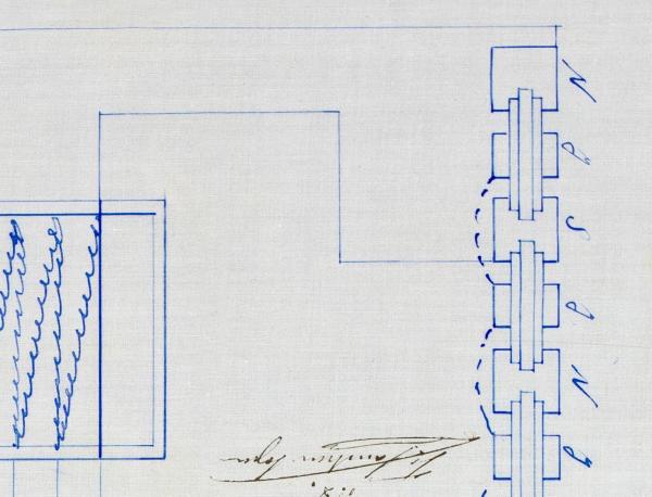
By the way, those who are convinced the N S notation in the patent and patent drawings means North and South poles, just look at Hanon's picture from the 1914 patent. How can each inducer be all N or all S?
Regards
CMLeave a comment:
-
Bistander,Originally posted by bistander View Post
I find your explanation to be self contradictory. I read this as:
So yes, current always flows towards lower potential nodes but it always flows towards the higher potential nodes, as well as always flowing away from lower potentials.
Could you clarify please?
Thanks
Regards,
CMLeave a comment:
-
Current flow
Hi hanon,Originally posted by hanon1492 View Post
I saw this on the other thread. I guess they don't want me to post there. So I'll give it a go here.
Your premise is flawed. Current flows in circuits or loops. So yes, current always flows towards lower potential points (called nodes) but it always flows towards the higher potential nodes, as well as always flowing away from lower potentials.
Regards,
biLeave a comment:
-
Some days ago I posted a couple of question in the other thread :
Originally posted by hanon1492 View Post
Today I saw a post with kind of refering to my post:
Now I just need that somebody could explain me how the magnetic field can move directly between the electromagnets and the toroid ( ---> and <--- ) without passing to the electric field.Originally posted by marathonman View Post
.Leave a comment:
-
An interesting link with many similarities with Figuera's foundation. In that link they talk abouth Bloch Wall disconnection and reconnection as the common denominator in many OU devices. We are talking here with Figuera about moving the Bloch Wall.
Bloch wall disconnect and reconnect. The final design!

Leave a comment:
-
You are right hanon. The small steps are unecessesary and just causing the problem.Originally posted by hanon1492 View Post
We should be pulsing our coils at 2 levels instead of 8 using 50 or 60 cycle.
The wave-form would then look more like the second linear image.
We might also get somewhere with this thing.
Glad you saw the light.Leave a comment:
-
All those input signals (red signal and blue signal) should be around 50 or 60 Hz if your aim is to get AC output at a standard frequency. The small steps in the top image are just the results of the succesive contacts in the original commutator from the 1908 patent, not really needed nowadays if the driving signals are made with current methods. When one is at maximum the other is at minimum, when one is increasing the other is decreasing. This is the foundation to move the two fields.
 Last edited by hanon1492; 11-11-2016, 04:47 PM.
Leave a comment:
 UFO could bless us with one of his colorful drawings.
Leave a comment: