 Tweet
Tweet
Hello,
quick intro (new here): I have always loved tinkering with electricity projects. I used to build pretty complex LED light fixtures for reef aquariums, so I have some minor understanding of things. Anyway, since I�ve gotten rid of my reef tanks I�ve wanted to keep up my electricity tinkering and thought I�d start with a Bedini.
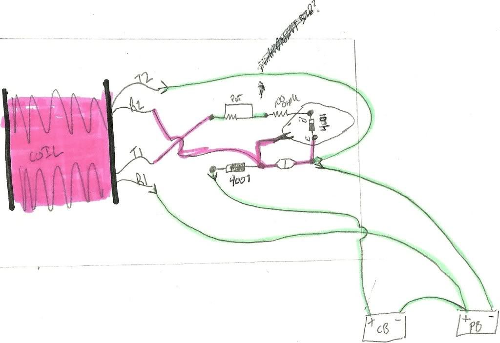
So I�ve built the circuit but it�s not working yet�.and I have a few idea�s why�.but I wanted to ask a couple things that I can�t seem to find the answer to online to help trouble shoot. I�ll probably rebuild my rotor, and then the coil also if that doesn�t work things out. So here�s the questions�
1) Does the size of the magnet affect rotation? For example I have some pretty big Neo�s and a pretty small coil. The neo�s are about 3� diameter and 1/4� thick (think they�re N35�s). The coil core is about 1/2� diameter (copper coated steel welding rods), and the coil OD is about 2.5� diameter. 26 awg and 30 awg. About 800 turns.
2) What should the coil�s ohms be when measured?
3) How important is bearing or rotor friction? I.e. can the rotor be a little stiff? I�m using some cheap $1.50 bearings and don�t really want to spend $20 on some German ones.
4) Is there a guideline or way to test for optimum magnet spacing?
5) Will more coils increase the torque potential of the rotor?
6) lastly what's the correct way to wire a 5 pin potentiometer for this application? or should I just go get a 3 pin?
Thanks.
quick intro (new here): I have always loved tinkering with electricity projects. I used to build pretty complex LED light fixtures for reef aquariums, so I have some minor understanding of things. Anyway, since I�ve gotten rid of my reef tanks I�ve wanted to keep up my electricity tinkering and thought I�d start with a Bedini.
So I�ve built the circuit but it�s not working yet�.and I have a few idea�s why�.but I wanted to ask a couple things that I can�t seem to find the answer to online to help trouble shoot. I�ll probably rebuild my rotor, and then the coil also if that doesn�t work things out. So here�s the questions�
1) Does the size of the magnet affect rotation? For example I have some pretty big Neo�s and a pretty small coil. The neo�s are about 3� diameter and 1/4� thick (think they�re N35�s). The coil core is about 1/2� diameter (copper coated steel welding rods), and the coil OD is about 2.5� diameter. 26 awg and 30 awg. About 800 turns.
2) What should the coil�s ohms be when measured?
3) How important is bearing or rotor friction? I.e. can the rotor be a little stiff? I�m using some cheap $1.50 bearings and don�t really want to spend $20 on some German ones.
4) Is there a guideline or way to test for optimum magnet spacing?
5) Will more coils increase the torque potential of the rotor?
6) lastly what's the correct way to wire a 5 pin potentiometer for this application? or should I just go get a 3 pin?
Thanks.


Comment