Announcement

Collapse
No announcement yet.

COP 20.0 (2000%) Demonstration

Collapse
X
 
  • Filter
  • Time
  • Show
Clear All
new posts

  • Here is a single cap simulation of one switching scheme which is not ideal and is limited by the simulator clock capabilities but it illustrates that 320W peak power through load, is obtained from 831VA reactive power. So the generator needs to support this reactive power but it is returned to the generator. You still have all the transmission line losses remember.

    Ideally 2 caps should be used with each cap charging in alternate half cycles and then discharging in the next alternate half cycles. This will give you the waveform shown in the presentation.

    You can partially see this in the simulation but not exactly because the falstad simulator doesnt allow timing to be set up for each quadrant (1/4 cycle).

    Barry


    $ 1 4.9999999999999996E-6 13.097415321081861 47 5.0 50
    v 400 448 400 320 0 1 50.0 177.0 0.0 0.0 0.5
    T 464 352 560 416 0 0.11 1.0 3.3954918443849547 1.7033270709454484E-5 0.9999
    w 464 320 464 352 0
    w 464 416 464 448 0
    w 560 352 560 320 0
    r 592 320 688 320 0 24.0
    w 560 416 560 448 0
    p 560 416 560 352 0
    l 560 448 720 448 0 0.13 1.7033270709898574E-5
    c 880 352 880 416 0 1.9999999999999998E-5 111.9773684933316
    159 752 320 688 320 0 0.1 1.0E10
    w 832 320 880 320 0
    w 880 320 880 352 0
    w 832 448 880 448 0
    w 880 448 880 416 0
    w 800 272 928 272 0
    w 832 448 768 448 0
    w 592 320 560 320 0
    w 800 272 752 272 0
    w 752 320 832 320 0
    w 720 448 768 448 0
    w 752 272 720 272 0
    w 720 272 720 304 0
    w 656 512 928 512 0
    w 928 512 928 272 0
    R 656 512 608 512 1 2 200.0 2.5 2.5 2.2689280275926285 0.4
    r 464 448 400 448 0 0.01
    w 400 320 464 320 0
    o 0 32 0 35 179.79859685352167 14.383887748281737 0 -1
    o 0 32 1 291 1757.6744692288928 6.103515625E-55 1 -1
    o 9 32 0 34 574.0653476371273 2.8703267381856366 2 -1
    o 9 32 0 33 214.30172143725346 8.572068857490141 2 -1
    o 5 64 1 35 559.9361855444511 9.765625E-105 3 -1
    Attached Files

    Comment


    • Trying a JPG this time
      Attached Files

      Comment


      • Reactive Power

        Going back over the Babcock presentation Time 1.05.30, he does state that the SERPS intentionally produces a reactive load to the generating source.

        Here are a few comments I picked up on the web about reactive power and generators...

        Reactive power would put no extra load on a generator shaft if everything were perfect.
        However, real generators have real losses, with some of those proportional to the square of the current.
        The reactive load causes more current in the wires than there would be with a purely resistive load of the same real power.
        The extra current causes additional real power to be lost.
        The power companies would not tolerate mass reactive loads.


        For half each cycle, each reactive load is pushing power back into the phase/phases that is/are accepting energy.

        You can't recover chemical energy, and some of that energy fed back into the generator is lost, but some of the energy is fed back into rotating kinetic energy of the generator.
        Which makes the generator turn faster-slower-faster-slower etc.

        A small generator does not have much rotating kinetic energy, so most of this energy is lost, and it just stresses the system.

        Perhaps SERPS is better suited to wind generators?

        Barry

        Comment


        • Reactive+Energy+Extra

          Originally posted by Listener192 View Post
          Going back over the Babcock presentation Time 1.05.30, he does state that the SERPS intentionally produces a reactive load to the generating source.

          Here are a few comments I picked up on the web about reactive power and generators...

          Reactive power would put no extra load on a generator shaft if everything were perfect.
          However, real generators have real losses, with some of those proportional to the square of the current.
          The reactive load causes more current in the wires than there would be with a purely resistive load of the same real power.
          The extra current causes additional real power to be lost.
          The power companies would not tolerate mass reactive loads.


          For half each cycle, each reactive load is pushing power back into the phase/phases that is/are accepting energy.

          You can't recover chemical energy, and some of that energy fed back into the generator is lost, but some of the energy is fed back into rotating kinetic energy of the generator.
          Which makes the generator turn faster-slower-faster-slower etc.

          A small generator does not have much rotating kinetic energy, so most of this energy is lost, and it just stresses the system.

          Perhaps SERPS is better suited to wind generators?

          Barry
          Hi Barry

          The question is? Where? Where is the extra 20X coming from not so much that we can't do it. Statements like "You Can't" are uncalled for here because "they did" you are already a few years to late.

          Did they understand your argument when they built the machine?

          Did the Patent office see it as a violation or an unethical energy exchange?

          No No and No.

          So what you are thinking is not happening.

          Now as far as all of your posts about the definitions of power, they are standard replies. The truth is no one knows where this 20X is coming from.

          Dude, didn't you hear Paul say that now his generators only need a tiny portion of the fuel that they use up before? Hello?

          You see that was my question to and then I looked for the answer and found it. You don't think Paul has his own grid tie 60hz alternator winding?

          Mike
          Last edited by BroMikey; 07-25-2014, 02:41 AM.

          Comment


          • An Opinion

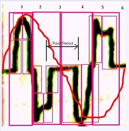
            Great job Mike. I'm going to pollute it with one crappy image to give my interpretation of this wave form. I have superimposed where, I think, the original, unbroken sine wave is. At the top is numbers to represent what I feel are important events in this image. Comments below image.

            1. First quadrant ( quarter ) of the sine. Terminated with first switch.
            2. Flyback from first switch off.
            3. Switch off with pause (important).
            4. Down side of sine terminating with switch off.
            5. Flyback from switch off.
            6. Final pause.

            When I say switch off I am referring to as it relates to the source. They obviously are redirecting between input, caps, gen coils, and output. Using the switches to change the circuit from gen/rlc/load to motor/load. Remember, they load both directions.

            That is my opinion of this wave form though I could be WAY out there. Please correct my understanding if I am.

            Randy

            Originally posted by BroMikey View Post


            This is a close up of the waves but I do not know what is what as far a what is called a quadrant.

            This is 1 or 2 cycles not really for sure coming out of the transformer (standard isolation type)


            Thanks Mike
            Last edited by tachyoncatcher; 07-25-2014, 03:54 AM.
            _

            Comment


            • Hi BroMikey,

              Firstly all simulations I have run albeit with less than perfect switching, confirm what Babcock and Murray are saying is correct, so I am not a naysayer.

              The simulated circuit is a resonant tank. In past experiments I have never had success in extracting power at these low frequencies from a resonant circuit, as the load usually kills Q. This configuration is different.

              The simulator doesnt allow the switching scheme Babcock and Murray are using to be replicated exactly, so to investigate further I am working on a build.

              I already have bidirectional power switches zerocross detectors etc, just waiting on parts for the timing side.


              Re my post you quoted..

              These were not my thoughts but comments from others regarding the effect of reactive power on generators generally, not related to, or in response to the release of the SERPS concept.

              These are my views regarding these comments...

              Transmission line losses: I agree these would be unchanged.

              You can't recover chemical energy: I would agree with this however the premise with SERPS is that you are not burning so much fuel in the first place.

              Recovery of rotational energy: This would happen every half cycle and I would agree that the power companies would not like millions of people putting large reactive loads on the line. Power station generators are designed to keep rotational speed, hence frequency within a tight tolerence while handling a nominal power factor. If you made all line loads reactive with SERPS these generators would not be able to maintain frequency and would have additional mechanical stresses placed upon them that would shorten bearing life etc.

              Small generators: I remain open minded about, hence my comment about wind generators. It would have been good to see SERPS function on a motor/generator set, so you could see the electrical power reduction to the driving motor.


              Barry

              Comment


              • Circuit Builds

                Originally posted by Listener192 View Post
                Hi BroMikey,

                Firstly all simulations I have run albeit with less than perfect switching, confirm what Babcock and Murray are saying is correct, so I am not a naysayer.

                The simulated circuit is a resonant tank. In past experiments I have never had success in extracting power at these low frequencies from a resonant circuit, as the load usually kills Q. This configuration is different.

                The simulator doesnt allow the switching scheme Babcock and Murray are using to be replicated exactly, so to investigate further I am working on a build.

                I already have bidirectional power switches zerocross detectors etc, just waiting on parts for the timing side.


                Re my post you quoted..

                These were not my thoughts but comments from others regarding the effect of reactive power on generators generally, not related to, or in response to the release of the SERPS concept.

                These are my views regarding these comments...

                Transmission line losses: I agree these would be unchanged.

                You can't recover chemical energy: I would agree with this however the premise with SERPS is that you are not burning so much fuel in the first place.

                Recovery of rotational energy: This would happen every half cycle and I would agree that the power companies would not like millions of people putting large reactive loads on the line. Power station generators are designed to keep rotational speed, hence frequency within a tight tolerence while handling a nominal power factor. If you made all line loads reactive with SERPS these generators would not be able to maintain frequency and would have additional mechanical stresses placed upon them that would shorten bearing life etc.

                Small generators: I remain open minded about, hence my comment about wind generators. It would have been good to see SERPS function on a motor/generator set, so you could see the electrical power reduction to the driving motor.


                Barry
                Hi Barry

                You are way over my head dude. My deepest apologies I am glad to hear you are on our side. You mentioned the small generators and then I remembered that in the video they were talking about putting the SERPS on wind farms or like he said that they would like to MARRY the technology with wind turbines.

                Also you mentioned reactive power, frequency and stress, my answer to that is "IF" the consumption of coal is reduced by 1000X wouldn't that lower stress?

                I am sure many would love to see your old setup plus the new one coming because it sounds like to me you are one up on us. Personally as far as building and designing I not not much help yet.

                My plan is that if someone shows me a circuit and how they are drawing off extra, I am off to the races so please show me anything you have time to.

                I know we all have our normal work and teaching may not always be easy, but I for one would like to see more building block type experiments is this direction.

                Thanks Barry for your explanation.

                Mike

                Comment


                • Hi Mike,

                  Re generator stress: In my last simulation 320W real power through load is comprised of +831W from the generator in the forward direction through the load with the cap storing charge, which then is returned through the load in the reverse direction -831W to the generator. This power would be considered reactive as it largely cancels.

                  However the +831W from the generator is a load driven by the prime mover which is burning fuel and the generator rotor is under torque for the first half cycle when this happens. When the -831W is returned in the second half cycle the torque on the shaft from the prime mover is negated as the power is turned into rotational torque on the generator rotor.

                  What I am saying here is the prime mover sees an intermittent Torque/Power demand every half cycle and rather than a continuous demand through 360 degrees of rotation. This is a mechanical stress on the system. If the rotor was large enough, the inertial mass may well even the torque fluctuation out and so the primer mover would just see a reduced torque requirement through 360 degrees. In a small generator this may not be the case though.

                  If this were a simulation including the electromechanical part I.e. the generator, there would be conversion losses which would add to the transmission line losses, so this would reduce the power returned.

                  I have posted some circuits over on Overunity.com for zero cross detector and a Bidirectional switch. I have used these previously on a capacitor based voltage multiplier which did not use any inductors. The isolated driver circuits do not use any special parts.

                  As SERPS has inductance in its resonant tank, I do have some transient recovery circuits that I have used on another project, that involved switching inductors at high current/voltage. These are not the same as Babcocks patented switch. I could employ variants of these, if switching transients become a problem.

                  By the way SCR's in series with IGBT's (SCR turn on and IGBT turn off), is not new. It was first used in rail gun design. This information has been in the public domain some time.


                  Barry

                  Comment


                  • Originally posted by Listener192 View Post
                    Hi Mike,

                    By the way SCR's in series with IGBT's (SCR turn on and IGBT turn off), is not new. It was first used in rail gun design. This information has been in the public domain some time.


                    Barry
                    SCR IGBT hybrid railgun design
                    Attached Files

                    Comment


                    • also opinion

                      The rendering of the waveform there is a timing in there can be approximated there is a sequence of two and inverted two. The first wave resembles half an ellipse and the second is a trapezoid common in motor switching and has a bottom of an offset sine spliced into top of the trapezoid then the next sequence is inverted. This looks like microprocessor programmed wave. The output has been converted to 2 sequence positive.
                      Last edited by mikrovolt; 07-25-2014, 12:14 PM.

                      Comment


                      • I believe this how the wavform is obtained.

                        Barry
                        Attached Files

                        Comment


                        • Paup Babcock's Iron Shot Core Recipe

                          Gentlemen,

                          The iron shot Paul uses is from Precision Reloading, Inc. They also have a web site.

                          PO Box 122
                          Stafford Springs CT 06076
                          860-684-5702

                          It is called Steel Shot Zinc Plated for Shotshell Reloading size #7

                          Paul places a single loose layer of these pellets into the bottom of a box and sprays them with Krylon Crystal Clear Acrylic (available at Wal-Mart) canned spray paint. He lets them dry and repeats the process until enough coated pellets are so treated for the project at hand. Next they are hand packed into a suitable form that has been lined with common baking wax paper a tablespoon at a time.

                          A layer of high quality 24-hour clear Epoxy is poured over that. The pellets can be moved around as necessary and then another layer of pellets and epoxy are again applied.

                          The form is filled one layer at a time until full and then allowed to cure for a couple of days. The core is then removed from the form. Edges and imperfections can be sanded away as needed.

                          I don't know if any advanced technical analysis has been done on the performance of this kind of core. Paul maintains that it is superior to using copper coated iron welding rods and favors odd shapes.

                          Spokane1

                          Comment


                          • Thanks Mark! I will definitely give this a shot.

                            Randy

                            Originally posted by Spokane1 View Post
                            Gentlemen,

                            The iron shot Paul uses is from Precision Reloading, Inc. They also have a web site.

                            PO Box 122
                            Stafford Springs CT 06076
                            860-684-5702

                            It is called Steel Shot Zinc Plated for Shotshell Reloading size #7

                            Paul places a single loose layer of these pellets into the bottom of a box and sprays them with Krylon Crystal Clear Acrylic (available at Wal-Mart) canned spray paint. He lets them dry and repeats the process until enough coated pellets are so treated for the project at hand. Next they are hand packed into a suitable form that has been lined with common baking wax paper a tablespoon at a time.

                            A layer of high quality 24-hour clear Epoxy is poured over that. The pellets can be moved around as necessary and then another layer of pellets and epoxy are again applied.

                            The form is filled one layer at a time until full and then allowed to cure for a couple of days. The core is then removed from the form. Edges and imperfections can be sanded away as needed.

                            I don't know if any advanced technical analysis has been done on the performance of this kind of core. Paul maintains that it is superior to using copper coated iron welding rods and favors odd shapes.

                            Spokane1
                            _

                            Comment


                            • Very clear examples

                              Originally posted by Listener192 View Post
                              I believe this how the wavform is obtained.

                              Barry

                              Wow yeah I see it now thanks Barry.

                              I think you are right as to this being chopped up and moved around and the ETO stuff is old I agree, with the scr and fet.

                              Mike

                              Comment


                              • Spokane1 (Mark)
                                Thank you for taking the time to explain about Paul's epoxy iron shot core.

                                There should be a non-hertzian relation to timing that will adjust more than serps.
                                Last edited by mikrovolt; 07-26-2014, 04:48 AM.

                                Comment

                                Working...
                                X