Announcement

Collapse
No announcement yet.

BiTT OverUnity Transformer Bi-Toroid Thane H. Bill A.

Collapse
X
 
  • Filter
  • Time
  • Show
Clear All
new posts

  • #76
    A word of support

    Hi Mike,

    I just now had time to get caught up on this thread. Your OU report of four days ago really shook the trees. All the baboons come after you when you do that. Fractions of a watt don't impress many people but it sounds like your basic SFT setup might handle more going forward. Remember what I said about incremental improvements. You have put forward enough details for any serious builder to replicate your device. I know you plan to stay at it and I think you will add to your present accomplishment. I like what you have done so far.
    There is a reason why science has been successful and technology is widespread. Don't be afraid to do the math and apply the laws of physics.

    Comment


    • #77
      Greetings

      Hello wayne

      Glad to see you coming around. Thanks for the kind words.

      Also I will use this opportunity to post some driver circuits for a more efficient BiTT. You see folks it's not enough to post circuits without testing them, expecting results for every experimenter who drives by.

      Up until now all I have posted are the beginner circuits that Kurt used and a million other experimenters who want to drive coils. Not good enough if we stop right here.

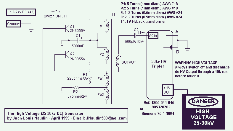
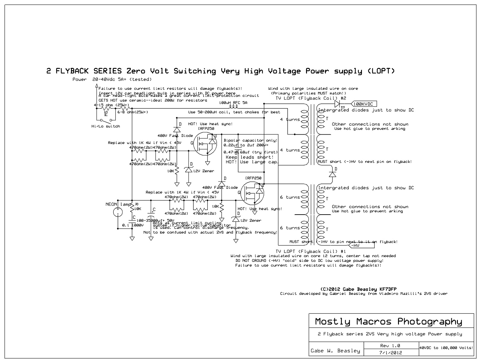
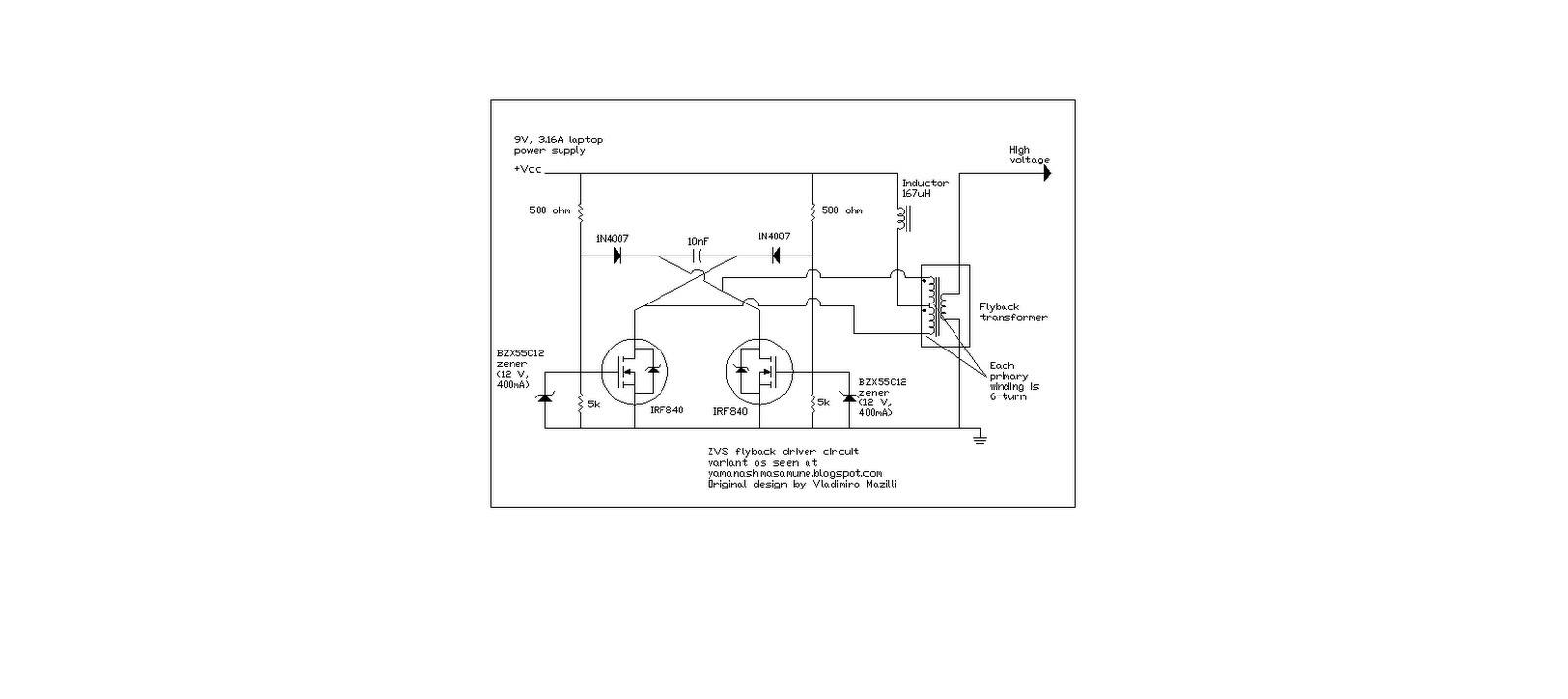
      There is nothing wrong with starting at the beginning but let's finish the job also. I will be posting ZVS circuits from here on out as these circuits are far superior to the pulse dc fast saturating as Kurt said.

      Kurt said that there was no comparison. Most of you may not have had time to even watch Kurts video's but he did stop using that circuit I have been posting of his.

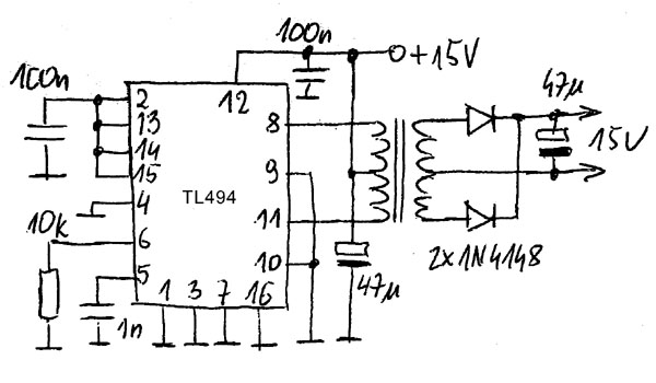
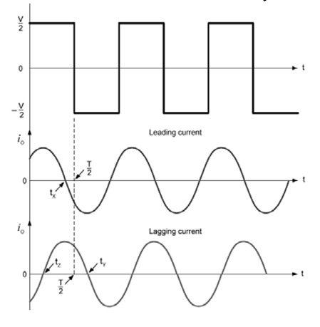
      These circuits are the right idea. Kurt said he used a tl494 to a split primary of his new ZVS. What is a ZVS? It is a circuit that sends a dc pulse upward and the next pulse goes down ward crossing the zero line then repeats. This is the next best thing to a true AC sine wave.


      Originally posted by wayne.ct View Post
      Hi Mike,

      I just now had time to get caught up on this thread. Your OU report of four days ago really shook the trees. All the baboons come after you when you do that. Fractions of a watt don't impress many people but it sounds like your basic SFT setup might handle more going forward. Remember what I said about incremental improvements. You have put forward enough details for any serious builder to replicate your device. I know you plan to stay at it and I think you will add to your present accomplishment. I like what you have done so far.

      Comment


      • #78
        ZVS drivers MEG

        Here Kurt shows you the waveform of his ZVS telling you that the voltage on the secondaries is higher due to the fact that this wave generator in the primary works better. Also i am continuing to post possible ZVS flyback drivers that preferably that have an adjustable frequency.


        https://www.youtube.com/watch?v=UNmj8nJyuuY


        Comment


        • #79
          Some ZVS "Zero" "Voltage" "Switching" are full bridge meaning there are 4 Mosfets toggling the wave on the output where the have bridge has only two Mosfet's.

          This is a full Bridge waveform


          How to Build a ZVS Driver, Run, and Mosfet Failure - YouTube


          Here is the half bridge wave shape


          Last edited by BroMikey; 11-30-2014, 01:36 AM.

          Comment


          • #80
            Zvs

            To properly power a transformer winding some form of AC must be used. In the case of the BiTT/SFT this is true. Many experimenters can not build these circuits and I think this is what stops the progress in this area of research.

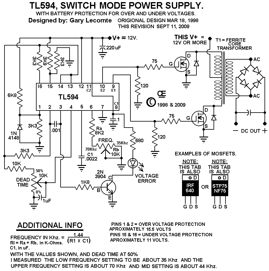
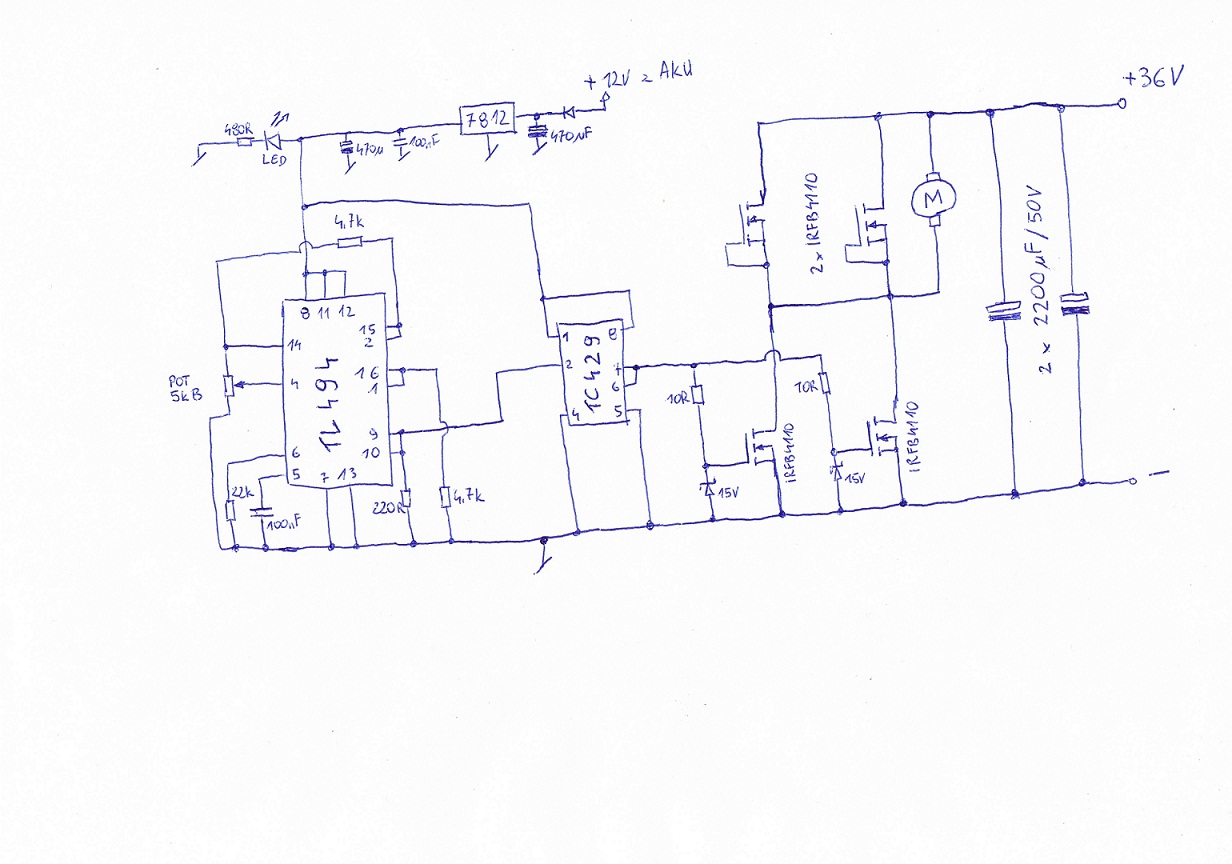
            I am using a tl594 to feed a TC4420 then to a mosfet to get a standard DC pulse in the upward direction. Now i would like to use these same componets to make the pulses like this circuit does.


            The problem with some of is the circuit is not very adjustable but a tl594 or others could be added.


            Last edited by BroMikey; 12-01-2014, 02:32 AM.

            Comment


            • #81
              Powering Up

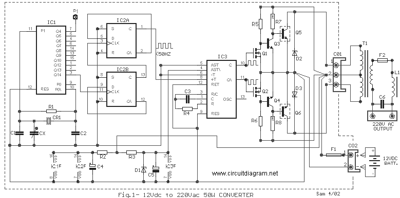
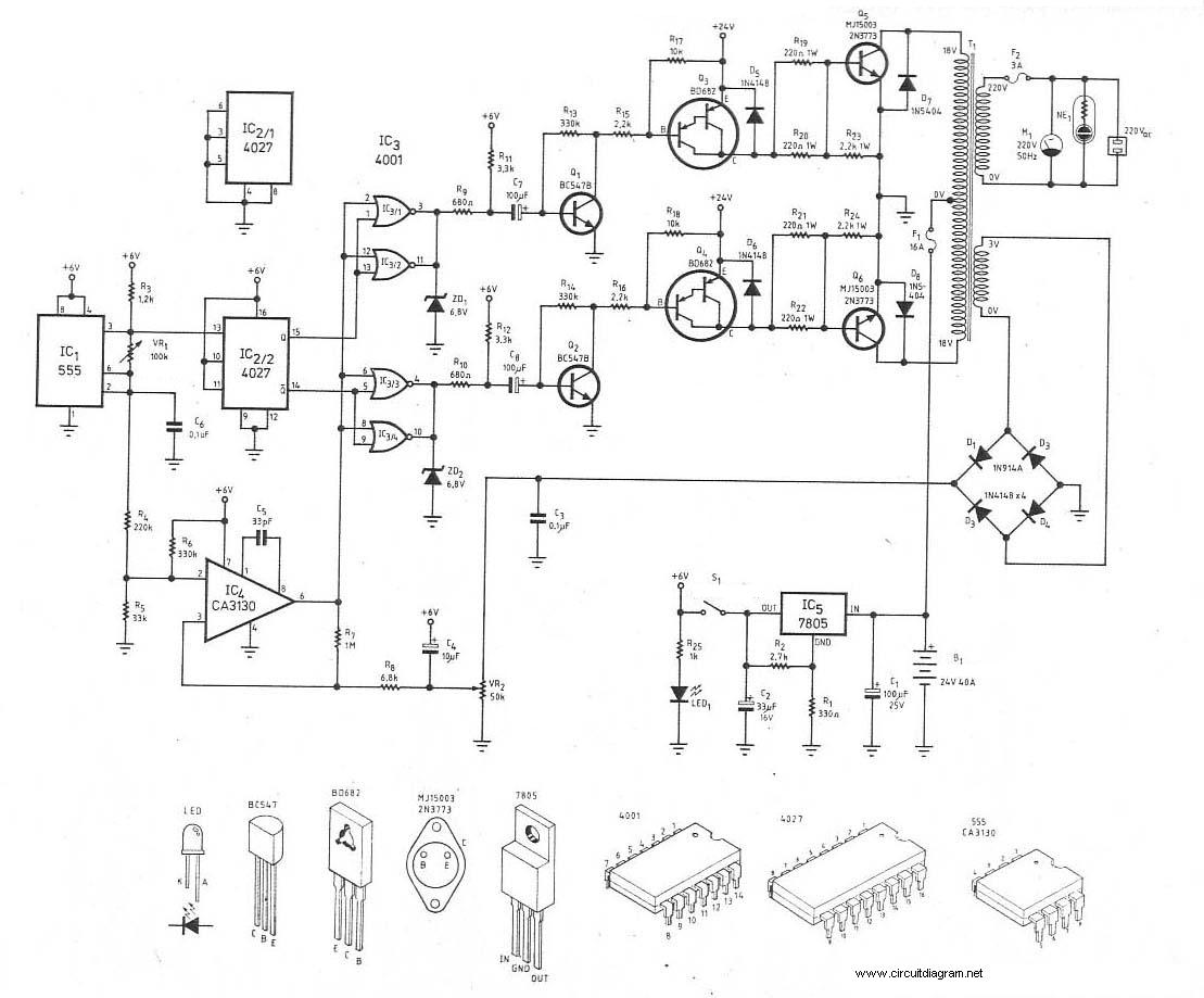
              In order to properly power up the windings of a Bi-Toroidal Transformer from a 12vdc source, an adjustable frequency inverter is needed.

              Also known as a VFD "Variable Frequency Drive"


              This website has devoted time to teaching and though you may not have time to build every circuit that I post, much can be learned from reviewing this material.

              Most of these inverter circuits could be altered to adjust dead time as well as duty and freq.

              Free Schematic Diagram at www.circuitdiagram.net


              300Watt Inverter DC 24V to AC 220V | CircuitDiagram.Net


              Comment


              • #82
                Firstly there is nothing to believe, there is no evidence of anything. Making over
                unity claims without providing any supporting evidence is very easy, actually
                anyone can do it anytime.

                It doesn't mater what anyone thinks of me or what anyone says of me, what
                matters is that there is no evidence of anything.

                I encourage people to experiment and try whatever they please, but if claims
                are to be even taken seriously there needs to be supporting evidence and the
                results should be repeatable.

                I myself have shown the effects Thane claims are OU with both the
                acceleration under load affects and the transformer version of that effect.

                There is no doubt that if a motor generator is setup to do it then it can be
                shown to accelerate when loaded, however in all cases it proves to be under unity
                and actually quite inefficient.

                In time I will also build a BiTT and show the claimed effects and why it isn't
                OU, But I will do it in my own time, people are free to doubt it but considering
                I achieved the acceleration under load and the transformer effect of it and I
                can do it at will with different setups, I have no doubts I can do it when I
                get the time and I'm up to it. Getting a reduction in input when load are
                applied is very easy as well, not OU either.

                I find it comical that Thane is so completely wrong and misleading on the
                acceleration under load effect and the transformer version of it, and yet
                people still think he did not do the same misleading and mistaken claims with
                the BiTT.

                Science is evidence based not hearsay claim based.

                I honestly hope you can get some OU and show some credible evidence of it.
                If even one shred of what Thane claimed was true it would be proven beyond
                doubt by now.

                As long as you don't expect anyone to believe the claims then there is no
                reason to show any evidence, but expecting sane people to believe OU
                claims without any credible supporting evidence does not even make sense.

                ..

                Comment


                • #83
                  Why it isn't OU?

                  Just look at your own words. You are looking for it to be Under Unity and as long as you do that Under Unity is what you will find.

                  Here we go. The earth is flat and extra energy is unavailable. And Thane is a Liar? And so many other men who show Over Unity? My My you are a mess Farmboy

                  You really are a SAD SAD case huh? Did you fall off the wagon?

                  Better put your order in at AURORATEK scooters.

                  I have an idea, go get some extra energy any way you feel you can like a solar panel or a water wheel, then start a thread here to post the results. Start there and you will surprise yourself.

                  Pedal powered, something.

                  Mikey Can't got stuck in the mud but try pull him out.


                  Originally posted by Farmhand View Post
                  I myself have shown the effects Thane claims are OU with both the
                  acceleration under load affects and the transformer version of that effect.
                  ............... however in all cases it proves to be under unity
                  and actually quite inefficient.

                  I find it comical that Thane is so completely wrong


                  In time I will also build a BiTT and show the claimed effects and why it isn't
                  OU,

                  Science is evidence based not hearsay claim based.


                  ..
                  Last edited by BroMikey; 12-03-2014, 02:15 AM.

                  Comment


                  • #84
                    The Jetson Self-Charging Electric Scooter (SSES)
                    500 Watt Brushless Hub Motor with 48 VDC 12 Ah Sealed Lead Acid Batteries.

                    Delivery beginning: January, 2015

                    Retail Price (MSRP): $1495.00

                    Imagine NEVER attaching a battery charger to recharge your electric scooter again!

                    AuroraTek introduces The Jetson 3X48 Self-Charging Electric Scooter (SSES) using patent-pending SmartPAK / SFT technology.

                    The Jetson SSEC is an innovative new electric vehicle that is revolutionizing personal transportation and rehab mobility at home and in the workplace. Three wheels provide greater stability and safety than regular two wheeled transporters, not to mention more torque and longer range for more rigorous use. The sturdy seat is removable, so you can stand up or sit down while riding making it great for recreation or mobility use. With speeds up to 20 miles/hr (35 km/hr), the Jetson is the ultimate in a comfortable, Pre-Mobility Electric Scooter. The new collapsible handlebar makes it a cinch to store or transport. Just drop the handlebars and store it in the back of the RV, van or trunk. The all-new design increases ease of operation by locating the controls and battery feedback with the brakes on the handlebar along with the keyed ignition. The headlight incorporates a powerful, new 7 LED design. Now you can see be seen. The Jetson SSEC has the same or better performance than other mobility devices and operates at no electric cost. The scooter has zero exhaust emissions, making it great for indoor use and personal transportation outdoors. It has a range of 25 miles (40 km) between self-charging cycles.

                    The Jetson Self-Charging Electric Scooter is truly a product for young and old. It's backed by a two year warranty on parts and labor from date of purchase.


                    Comment


                    • #85
                      I need a bit of help with this. I watched Thane's transformer video and he
                      seems to go on about lowering the power factor. Our electricity supply
                      company starts charging extra when the PF. gets below 0.95.
                      What would the practical implementation of these transformers be?
                      John.

                      Comment


                      • #86
                        Practically Speaking

                        Hi John

                        Well the way the Patent info reads and all of the video's of THANE H and BILL A

                        They say when the current is 90 degrees out of phase (Leading) that the loads put on the secondary do not increase the primary power draw.

                        I a standard transformer the opposite is true. Everybody knows that a conventional transformer increases in current draw all the way around.

                        So if the primary is drawing 1 amp at idle then as the demand calls for more power to supply the load the current will skyrocket to 10 amps if the unit is as large as a microwave oven transformer.

                        I have hooked up my BiTT/SFT wrong and it draws power just like a normal one but if done correctly the idling current in the primary will not change.

                        Now having said that there is much more to explain.

                        "IF" you can do this first step then tuning is next. "IF" tuning is done right you will be looking at many many frequencies that optimizes the input output relationship that you are after.

                        This is the basic idea. So when you draw 1 amp using a normal transformer 95 percent of that amp is consumed with 5 percent being returned in the form of reactive power.

                        With the BiTT the same 1 amp under normal conditions around 78 degrees only 20 percent of that amp is consumed while 80 percent is reactive that will recirculate.

                        So from this you should see some difference between the two units.

                        The trick is to tune the secondaries so they both see the 1 amp and transform it into power while the primary only burns up 20 percent.

                        Of course the circuitry feeding the primary must be high frequency, tunable and conservative. Many of our present circuits that could be used to power the primary are only 50 percent efficient.

                        Then on the other end at the secondaries a translation must take place as well. Say that the output was 2 volts at 1 amp and you needed it to be 44vdc, well a converter would drop the systems overall collection depending on how things are handled.


                        Thanks for asking John

                        mikey


                        Originally posted by Iamnuts View Post
                        I need a bit of help with this. I watched Thane's transformer video and he
                        seems to go on about lowering the power factor. Our electricity supply
                        company starts charging extra when the PF. gets below 0.95.
                        What would the practical implementation of these transformers be?
                        John.
                        Last edited by BroMikey; 12-03-2014, 07:31 AM.

                        Comment


                        • #87
                          Power Factor Penalty

                          Originally posted by Iamnuts View Post
                          Our electricity supply company starts charging extra when the PF. gets below 0.95.

                          What would the practical implementation of these transformers be?
                          Below 95%, holy crap. What that really translates to is we need to get you off the grid and as quickly as possible.

                          Keep this handy because we will use it for some examples and you will surely want to use it to verify your electrical billing:
                          Power factor correction calculator

                          Suppose you have a typical 1500 watt isolation transformer for your bench equipment. You bought a big one to make sure it could handle everything. So you plug everything in and power up. Let's say you are drawing 1.5kW, 13 amps, 120 volt, 60Hz. We run the numbers and it tells us your power factor is 96%. Not bad and you shouldn't be getting penalized. You will notice the Power Factor is equivalent to the absolute value of the cosine of the phase angle. So lets take the arc cosine of the Power Factor and see what we have. I get roughly 16.3 degrees, which tells us the voltage/amperage sine waves are that much out of phase from each other.

                          Now lets keep the same setup and begin to turn some of your equipment off; everything is still plugged into your isolation transformer. Now we measure 1.0kW, 13 amps, 120 volt, 60Hz. Running the calculator we see a Power Factor of 64%. Ouch! Plan on getting dinged severely for this. The phase angle now computes to roughly 50 degrees.

                          Go a step further and turn everything off, but leave the isolation transformer plugged in. As you would guess, the Power Factor goes to zero, but now you not only pay for all that reactive power, you pay a penalty too. Moral of the story is don't use any transformers unless you run them at full rated load and shut them off when not in use.

                          Now imagine using a BiTT or SFT that is by design built to stay far away from a phase angle difference of zero. You simply don't want such a device plugged into your wall.

                          Comment


                          • #88
                            Originally posted by BroMikey View Post
                            [SIZE="4"][FONT="Comic Sans MS"][FONT="Comic Sans MS"]The Jetson Self-Charging Electric Scooter (SSES)
                            500 Watt Brushless Hub Motor with 48 VDC 12 Ah Sealed Lead Acid Batteries.
                            Here is their explanation:

                            SCIENCE

                            Comment


                            • #89
                              He continues

                              The Split-Flux Bifilar Transformer (SFT) Operating Performance
                              By William S. Alek
                              President and CEO
                              July 15, 2014

                              The operating characteristics of traditional transformers have been well understood by mainstream science for well over a century.
                              Transformer - Wikipedia, the free encyclopedia

                              By comparison, the Split-Flux Bifilar Transformer (SFT) developed at AuroraTek has a very different operating characteristic. Shown below is a remarkable graph that compares the operating performance of the SFT and the Traditional Transformer:

                              The graph shows the Voltage Current Phase Angle vs. Transformer Efficiency. You'll observe the Traditional Transformer can never exceed an efficiency of 100%. On the other hand, as the Phase Angle of the SFT approaches 90 degrees, the Efficiency reaches POSITIVE Infinity. On the other side of 90 degrees, it becomes NEGATIVE Infinity. At this point, the SFT becomes a power source, delivering power back to the generator. In other words, as the Phase Angle continues to increase, more power is being delivered back to the generator. The generator becomes a motor. Interestingly, the Efficiency curve of the SFT resembles a hyperbolic function.

                              Comment


                              • #90
                                Yes DogOne,
                                It all depends on your contract. You get metered on two sides of
                                the triangle at half hourly intervals.
                                It's amazing what can be done with several thousand dollars worth of
                                capacitors!
                                What would be a suitable application for a BITT?
                                Old Thane's transformer is nearly jumping of the bench it's buzzing that
                                harshly.
                                John.

                                Comment

                                Working...
                                X