 Tweet
Tweet
To preface this thread, a quote by Eric Dollard:
A quote by John Bedini:
A magnetic amplifier (magamp) is a specially designed inductor that allows for variable power flow with a small input much like a transistor. The magamp, in its simplest configuration, consists of at least two windings and a magnetic permeable core. One winding is is called the control winding and the other is the AC (power) winding.
The idea of operation is that one applies a small DC bias current to the control winding which in turn, saturates the permeable core and lowers the impedance (by lowering the inductance) of the AC winding. A simple illustration taken from Wikipedia can be seen below.

The fundamental components shown in the illustration above are a bit inefficient by themselves. Further modification needs to occur before one has minimum-energy-loss magamp.
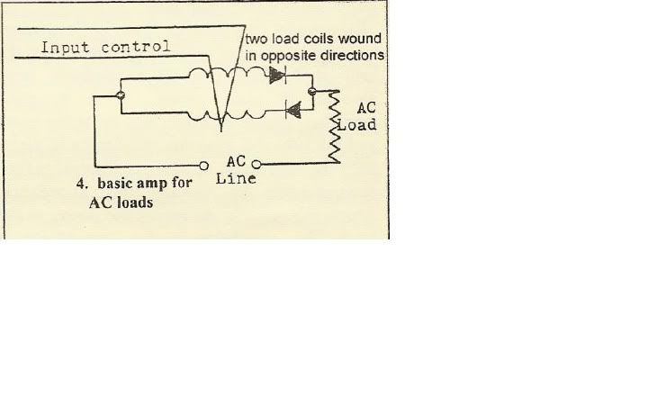
When there are only two windings (AC and Control) on a magamp core, the AC winding will perform a transformer action on the control winding. This is undesirable for two reasons: the flux on the control winding will cause instability in the control winding bias and also, there will be unnecessary energy loss from the power winding. This can be eliminated by adding another AC winding wound in the opposite direction as the first and a couple of diodes. This can be seen in the illustration below.
For further reading about magamps, George Trinkaus has edited a paper which highlights the fundamentals of magamps which can be found here: http://www.themeasuringsystemofthego...amplifiers.pdf
Eric Dollard has developed the Four Quadrant Theory of Electricity. The Idea behind the four quadrants is there is a quadrant for inductive biased power consumption, a quadrant for capacitive biased power consumption, a quadrant for inductive biased power production, and a quadrant for capacitive biased power production.
Normally in electrical engineering, since steady state currents are "desirable", the quadrants of of of power production are not readily seen. It is only when one synchronously varies the parameters (capacitive or inductive) that the power production quadrants are achieved.
The following is an illustration and a quote by Energetic Forum member garrettm4:

The illustration and description above describes what Mr. Dollard was referring to when he said "parameter variation at the 2nd harmonic represents power". The fundamental concept is to charge the inductor in a low impedance state and discharge in a high impedance state. This type of synchronous inductance variation is what will begin to produce a negative power factor.
Armagdn03 wrote a good series of posts that describe what is happening with the magnetic flux in the core. The posts start here: http://www.energeticforum.com/renewa...tml#post144398 The posts continue on to the next page of the thread.
This thread has been started for the discussion of different magamp configurations and experimental results. There are many different variations of magamp cores. I personally will be starting out with a toroid due to availability issues. Any core configuration discussion is welcome so long as the control winding changes the inductance of the AC winding and the AC winding has minimal coupling to the control winding.
I encourage you all to google magamp cores and find distributors that are willing to sample their cores for R&D purposes. There are many out there and at worst case scenario, they will charge you for shipping and handling.

Dave
In my mind parameter variation at the second harmonic represents power but parameter variation at the third harmonic represents energy. These
are just ideas, see Steimetz A.C. Theory book in his parameter variation
chapters. The magnetic amplifier of E.F.W. Alanderson is definitely the
way to go.
are just ideas, see Steimetz A.C. Theory book in his parameter variation
chapters. The magnetic amplifier of E.F.W. Alanderson is definitely the
way to go.
The Germans already had over unity devices and were using them and the Mag Amp was at the root of that.
The idea of operation is that one applies a small DC bias current to the control winding which in turn, saturates the permeable core and lowers the impedance (by lowering the inductance) of the AC winding. A simple illustration taken from Wikipedia can be seen below.
The fundamental components shown in the illustration above are a bit inefficient by themselves. Further modification needs to occur before one has minimum-energy-loss magamp.
When there are only two windings (AC and Control) on a magamp core, the AC winding will perform a transformer action on the control winding. This is undesirable for two reasons: the flux on the control winding will cause instability in the control winding bias and also, there will be unnecessary energy loss from the power winding. This can be eliminated by adding another AC winding wound in the opposite direction as the first and a couple of diodes. This can be seen in the illustration below.
For further reading about magamps, George Trinkaus has edited a paper which highlights the fundamentals of magamps which can be found here: http://www.themeasuringsystemofthego...amplifiers.pdf
Eric Dollard has developed the Four Quadrant Theory of Electricity. The Idea behind the four quadrants is there is a quadrant for inductive biased power consumption, a quadrant for capacitive biased power consumption, a quadrant for inductive biased power production, and a quadrant for capacitive biased power production.
Normally in electrical engineering, since steady state currents are "desirable", the quadrants of of of power production are not readily seen. It is only when one synchronously varies the parameters (capacitive or inductive) that the power production quadrants are achieved.
The following is an illustration and a quote by Energetic Forum member garrettm4:
The, 2x frequency, blue square wave shown is one of the control signals for the circuit and for the sake of discourse we will say it controls the MagAMP in the above circuit diagram. The green sine wave is that of voltage and is in a quadrature relationship with the purple sine wave of current and the black, 2x frequency, is that of power, something that will interest you is that the power waveform goes into both the top and bottom half of the graph, this represents reactive power or a surging to and fro of stored and returned energy. Something to take note of, is if, the black waveform is on one side or the other, top or bottom of graph with respect to the x axis, this would mean unilateral transfer of power is taking place, or simply power dissipating into a load. Dependent upon the actions taking place in the circuit, the power waveform can be any place between the two points of top/bottom or in between. Thus you could see in a device that returns more power than it consumes, such as in the circuit above, that the power wave form will be smaller on top and bigger down below where it is situated on the x axis. Thus the source input becomes a quasi-load and the load now a quasi-source. The understanding that power is a product of voltage and current, with phase angle taken into account, and the direction of its flow is fundamental in making one of these devices work. Now back to the blue control waveform as seen above, the current pulsed into the control winding of the MagAMP controls its relative saturation or capacity at any one moment in time. Thus you would saturate the core from the zero crossing / rise to peak portion of the purple wave and desaturate at the peak to fall / zero crossing portion. Thus inductance changed from L0, low inductance to L1, high inductance at the proper times.
Armagdn03 wrote a good series of posts that describe what is happening with the magnetic flux in the core. The posts start here: http://www.energeticforum.com/renewa...tml#post144398 The posts continue on to the next page of the thread.
This thread has been started for the discussion of different magamp configurations and experimental results. There are many different variations of magamp cores. I personally will be starting out with a toroid due to availability issues. Any core configuration discussion is welcome so long as the control winding changes the inductance of the AC winding and the AC winding has minimal coupling to the control winding.
I encourage you all to google magamp cores and find distributors that are willing to sample their cores for R&D purposes. There are many out there and at worst case scenario, they will charge you for shipping and handling.
Dave
 I have only simple sinewave wein-bridge circuit and small car audio amplifier 20W :-(. Did you rewound transformer primary to get 4 or 8 ohms resistance ?


Comment