Announcement

Collapse
No announcement yet.

Bessler wheel; how I see it

Collapse
X
 
  • Filter
  • Time
  • Show
Clear All
new posts

  • Bessler wheel; how I see it

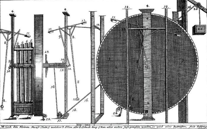
    Few days ago a friend, Sepp Hasslberger, introduce me the wheel of Bessler.
    After thinking about it, this is how I see it;

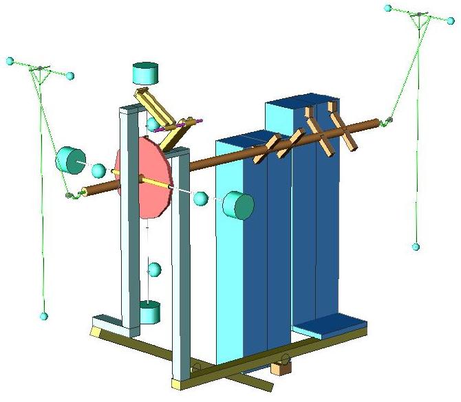
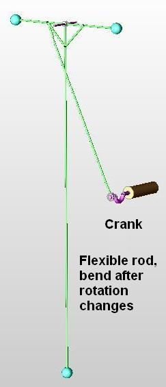
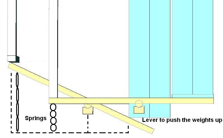
    The pendulums are energy storage devices. The crank allows for storage when the wheel speeds and to drive it when the wheel slows.
    The long and small bob have to purposes; the first to store extra energy, bending when the rotation accelerates and the second as a damper, vibrating at higher speeds (mechanical resonance).

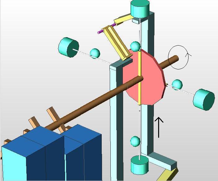
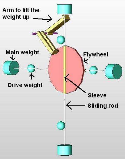
    The wheel is a parametric oscillator, with pairs of weights on the sliding rod thru a sleeve.
    Near the center, smaller radius possible, and horizontally up, is the better point to apply the force to change the trajectory.
    Different torque rates and leverage are used in the arms that transmit the weights´ force falling.


    thermoenergetics
    Sepp Hasslberger

  • #2
    Hi everybody

    I have dimensionless Acad drawings to share.
    How can I post them here?
    David

    Comment


    • #3
      You seem to be more clever than most of us here, very impressive work!

      Hopefully someone smarter than I does understand what you're seeing, and put it in a Phun simulation.

      Do you think your understanding of the wheel would allow for work to be extracted, while rotation speed is kept?

      Comment


      • #4
        I've always thought that the Bessler wheel picture posted was nothing more than a large wind up watch. Does anyone know what year Bessler made his device?

        Just looked it up 1715.
        Last edited by Mark; 07-24-2010, 12:26 PM.

        Comment


        • #5
          Originally posted by Cloxxki View Post
          put it in a Phun simulation.

          Do you think your understanding of the wheel would allow for work to be extracted, while rotation speed is kept?
          Hi Cloxxki
          I think so. With right balancing may be an OU.
          The Big weights are lift with high torque, on the shaft.
          Underneath, Bessler may had springs, that are under tension under the weight, and will help the shaft pulling them up
          The driving weight (small weight offset) shall be placed as close to the center as possible.
          When the working bar push it in, will take advantage of its slower angular velocity.
          I have a big feeling that will work, but you are right, only with computer simulation (Phun, Working Model) or a physical prototype will tell us.
          I change my mind, and will be the same if we put the lifting bar on the opposite side where I first placed it.
          Thank you
          23.JPG

          25.JPG

          Comment


          • #6
            With the lifting bar on the bottom

            4c.JPG

            Comment


            • #7
              I like your thinking. I had a similar idea about changing the diameter of the mass. The difference is that I am using another force to do the work.
              It's really about using the kinetic energy of the pendulum's velocity through centrifugal force. Using this force to alter the radius of the rotating mass allows gravity to become the prime mover. Otherwise there is no way to achieve an imbalance.
              As you can see below, the pendulum has two weights; one fixed and one movable. The axis of the pendulum is allowed limited vertical movement since it is on a lever arm. This movement is regulated by the spring on the left, and the stop on the other side of the fulcrum support.
              When the pendulum swings around in a clockwise direction, the centrifugal force compresses the spring and forces the axis downward. As the axis moves down, the bottom weight hits the ramp and is prevented from traveling down any further. Nevertheless, the fixed weight continues to compress the spring and force the pendulum arm down even more.
              This pushes the bottom weight up a channel in the arm, and into a latch which secures it fast.
              As the pendulum continues to turn, weight is taken off the spring and the pendulum starts back up. Since the center of gravity of the pendulum has been moved in towards the axis, the angular velocity increases. There is also less leverage for gravity to work against and so velocity and momentum are conserved.
              Additionally, there less time for gravity to decelerate the pendulum since the trip to the top takes less time at a higher speed.
              When the pendulum reaches the top of it's arc, the latch is released on the bottom weight. Either through centrifugal force, or a spring, the weight is forced out to the end of the pendulum again.
              This immediately slows down the angular velocity and increases the leverage. Gravity now has more time and leverage to impart energy to the pendulum as it descends to repeat the cycle once again.
              That's the general idea anyway. It's the same idea you and a lot of other people have had for a gravity wheel, but with an important twist.


              Cheers,

              Ted

              Comment


              • #8
                Originally posted by Matos de Matos View Post
                Hi everybody

                I have dimensionless Acad drawings to share.
                How can I post them here?
                David
                Change the extension from .dwg to .txt and use the attachment feature (paper clip icon).

                Users saving the file downloading the file will need to change the extension back to .dwg

                "Amy Pond, there is something you need to understand, and someday your life may depend on it: I am definitely a madman with a box." ~The Doctor

                Comment


                • #9
                  Originally posted by Ted Ewert View Post
                  That's the general idea anyway. It's the same idea you and a lot of other people have had for a gravity wheel, but with an important twist.


                  Cheers,

                  Ted
                  Hi Ted:
                  Nice setup.
                  I suppose that showing your idea is for us to comment on it.
                  That is my intention posting here, too. Please, criticize it, correct me, call me non sense, but say something; please nourish my knowledge.

                  I think that counter clock rotation will have less load on the fulcrum and more on the spring at descendent.

                  You are expecting that the spring brings the sliding weight to the top, its original potential energy, because centrifugal will do it at expense of angular velocity. If the weight moves out, slows the RPM.
                  To move the weight in, we only gain kinetic energy at expense of work on centripetal force.
                  You are not applying a force; kinetic energy will be exchanged for torque, heat and friction.
                  I think that if you drop it from the top, it will reach 9:00 o’clock.

                  Bessler was a watchman that used precision, tuning, and harmonics on his work.
                  I think that Bessler applied the force at the lowest angular velocity possible, to move the pendulum´s full arm in, and taking gain of the Mechanical advantage of the wheel (radius wheel/radius axel).
                  The force applied is tuned at right angles, and is regulated by the lever arm between the working weights and the driven weight, that is pushed in.
                  The position of the fulcrum is tuned, in such that the velocity of the arm moving up is in time with the resonance frequency of the drive weight, increasing the angular momentum.

                  The springs under tension, when released tuned with the arm on the shaft, will increase the momentum and reduce inertia, reducing the work of the shaft pulling them up.
                  The shaft´s drive is done when the arm pushes the drive weight on the wheel.
                  Various forces multiplied and tuned to absorb energy, this setup may surprise us.
                  Thank you
                  David

                  Comment


                  • #10
                    Bessler tuned an automatic mechanical well.
                    The Bessler wheel rotated at around 20 RPM. I think too, that at low angular velocity is better to apply the force up, with less loss of kinetic energy.
                    Can you folks help me doing a mathematical model of the mechanical well?
                    Weight lifted, dropped will cause an advantage that will turn the shaft that will lift the weight, and closes the loop.
                    The gain with the parametric pumping will be enough to feed the loop?
                    What is the ideal combination for the working weights =weights on wheel arms relationship, and the ideal radius for fixed weight (on end of arm) and driven weight (close to the axis).
                    Any left over?
                    Thank you
                    David
                    250px-Wheelaxle_quackenbosaaaa.GIF
                    Sketch 1.JPG

                    Comment


                    • #11
                      Hi David,

                      I have studied these configurations before and there are some things about them that are problematic. But I also know there are some things that can be applied to assist toward the final goal.

                      One thing that is problematic with the well driver, is that centrifugal force works against you even at 20 RPM. The weights will tend to be forced to the outside everywhere and that force will have to be overcome to bring them back to the center before the upstroke.

                      Now as far as moving the weights without impacting the torque on the wheel, that has a hidden problem. We know that any orthogonal force to the wheel will produce zero effect on the wheel torque. So the momentum of the wheel itself, the framework of spokes and rims, is conserved even though we move the weights around. But there is a conservation of angular momentum of the weights that occurs and a force will be present between the weights and the axles that adds to the frame acceleration as they are drawn inward and subtracts from it as they are drawn outward. So indirectly, a reactionary force does impact the wheel torque.

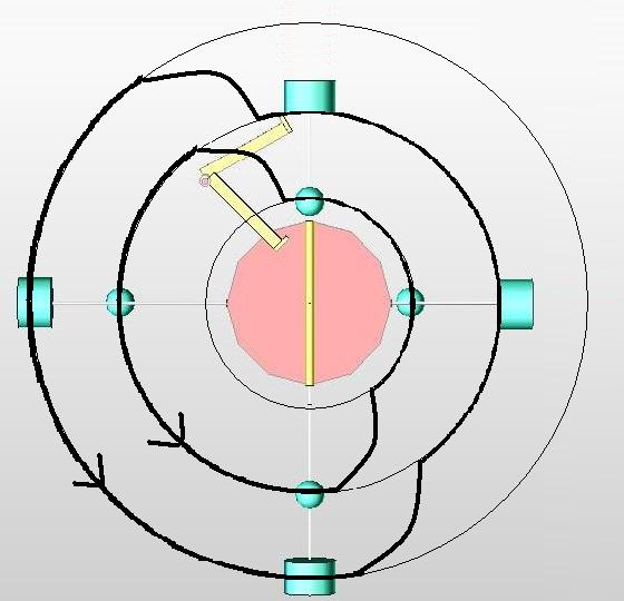
                      Perhaps a wheel inside a wheel and the middle turns faster but by synchronization we are able to slide the weights between the two. Would there be any advantage?

                      Or what about an horizontal wheel that is used to raise the weights by centrifugal force? Then the rods could change length that transfer the weights from one to the other. Taking the weights from the bottom of the vertical wheel and depositing them at the top

                      However we do it, even if we lay the wheel flat, move the weights around and then stand it back up again, we always end up lifting that weight with some force or energy. I suppose we could use high tide to float the weights to the top and then low tide to allow them to fall and in this way we will have truly used gravity 100% to turn our wheel. But it would be a slow moving 12 hour cycle and would have to be a really long cylinder type wheel with a lot of weight to be useful. But it could be constructed and it would work.

                      "Amy Pond, there is something you need to understand, and someday your life may depend on it: I am definitely a madman with a box." ~The Doctor

                      Comment


                      • #12
                        Just for discussion:
                        Zoom Image

                        Can you see why my design here fails even though the blue rollers are 15 foot long cylinders?

                        "Amy Pond, there is something you need to understand, and someday your life may depend on it: I am definitely a madman with a box." ~The Doctor

                        Comment


                        • #13
                          Originally posted by Harvey View Post

                          Now as far as moving the weights without impacting the torque on the wheel, that has a hidden problem. We know that any orthogonal force to the wheel will produce zero effect on the wheel torque. So the momentum of the wheel itself, the framework of spokes and rims, is conserved even though we move the weights around. But there is a conservation of angular momentum of the weights that occurs and a force will be present between the weights and the axles that adds to the frame acceleration as they are drawn inward and subtracts from it as they are drawn outward. So indirectly, a reactionary force does impact the wheel torque.
                          Hi Harvey:

                          I understand that we are exchanging torque for kinetic energy, when we move weights in or out in a wheel’s spoke.
                          It is energy transformation on the mechanical advantage of the wheel.
                          Energy input is necessary to conserve one of the two.

                          I think that Bessler was taking advantage of lifting weights on different reference frames.
                          I call them relativistic machines.
                          The picture below shows the mechanism.
                          There is any gain?

                          I can´t manage to attach the ACAD drawing.
                          Change the extention and do not upload.

                          Thank you
                          David
                          Sketch 2.JPG

                          Comment


                          • #14
                            I forgot, there is a file size limit also


                            As regards the 100kg being lifted by the wheel there are several factors to consider.

                            1. The real torque on the wheel delivered by the sliding 50kg weights will only be the differential of the arm lengths (leverage differential) because the weights are balanced.

                            2. The torque of the wheel must exceed 100kg to lift the 100kg weight, otherwise if they were equal it would only raise to half height.

                            3. The distance and timing must allow for an advantage. The trade off for using short pegs on an axle to increase the lifting torque, is that the lift is a lesser height.

                            So we find that we can either accumulate energy over time and release it all at once, or we can trade height for mass in the gravitational potential energy equation but the energy is still balanced out some how.
                            "Amy Pond, there is something you need to understand, and someday your life may depend on it: I am definitely a madman with a box." ~The Doctor

                            Comment


                            • #15
                              Originally posted by Harvey View Post


                              As regards the 100kg being lifted by the wheel there are several factors to consider.

                              1. The real torque on the wheel delivered by the sliding 50kg weights will only be the differential of the arm lengths (leverage differential) because the weights are balanced.

                              2. The torque of the wheel must exceed 100kg to lift the 100kg weight, otherwise if they were equal it would only raise to half height.

                              3. The distance and timing must allow for an advantage. The trade off for using short pegs on an axle to increase the lifting torque, is that the lift is a lesser height.

                              So we find that we can either accumulate energy over time and release it all at once, or we can trade height for mass in the gravitational potential energy equation but the energy is still balanced out some how.
                              Hi Harvey
                              The leverage distance provides the torque to lift the weights.
                              It balances out, like always.
                              Any load, and it will not reach the vertical upside down.
                              The model on the quest thread will tell if with an initial velocity, the down pendulum have or not higher velocity than the horizontal drop.
                              I thought about springs under the weights, but conservation is difficult to beat.
                              I am working on a setup that uses the same concept of parametric pumping with a centrifugal hammer to apply the force.
                              Give me a few days.
                              David
                              Sketch 4.JPG

                              Comment

                              Working...
                              X