 Tweet
Tweet
Environmental capacitive coupling
Capacity in general is an interesting beast, of which I have yet to wrap my mind around. Because of this my understanding is incomplete, and so my theories, are as always flawed. This being said, here are a few mental experiments which may help some move a step closer to their energy independence goals.
If you imagine a parallel plate capacitor, You know that the distance between the plates directly relates to the capacitance in a linear way. This is an interesting topic of conversation in and of itself, and we will return to this topic, but for now it is a starting point.
Imagine instead of plates, capacitive point particles, or spheres. Each has a free space capacitance, or a capacitance relevant to the environment in which it floats.
The field intensity around this particle or sphere is known to decrease with the inverse square of the distance, this is known as the inverse squared law. So for example, if you had a sphere charged to 16 volts, and doubled your radius and took a potential measurement you would find a potential value of 4.
This attribute affects this point particle spheres ability to affect its environment, and the effect the environment has on it. Now let�s wade through some mental experiments.
Imagine a parallel plate capacitor. Charge it up to an arbitrary value. Now, attempt to discharge only one plate of the capacitor by touching it to ground. Obviously this is not possible, nearly 100% of the charge on one plate, is within very close proximity to the other, and within their respective fields, they tightly hold onto their charges. This is one extreme.

Now imagine two spheres miles apart, charged to an arbitrary value. Because they are so far from one another, they really do not sit within the same environment, and so have very little if any mutual relation. Try and discharge one side of this capacitor, It will be quite easy, and the path of discharge will be to an object of differing potential. This is the other extreme of the spectrum. Here the person could touch the point charge (vandegraaff sphere) and because of her lower potential, the sphere will discharge into her and equalize.

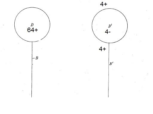
Now imagine Two spheres separated by some distance. This distance equals 2 doublings of the radius of each of the individual spheres. Therefore, if you have one of the spheres charged to 64v, the other will sit inside this inverse squared field and feel a strength of only 4v. (one doubling of the radius away and we would feel 16, two away and we feel 4) Again one could view each of these spheres as one plate of a capacitor.
One could charge each of these spheres to say�.64v. Now try the same as above, Try to discharge one side only of our capacitor. If you were to leave one side charged to +64v, then try to discharge the other side, you would find that you could only discharge it to -4v. This is because this distance (2 doubling of the radius) the +64v spheres field has a decreased field strength of +4v. Thus the second sphere when discharged will only discharge to the -4 level, to balance with its environment.
As you can see, because we have caused increased separation between the spheres, they have less �holding� power on each other. As the spheres get closer, they are immersed more and more in each others influence, and they behave more and more like a parallel plate capacitor. As they move further and further apart they behave more like individual point charges. The further they separate, the less they are coactively connected to one another, and the more they are coactively connected to their environment.
As the spheres move further and further apart, they become more and more like monopole entities. Their capacity is more and more in relation to their environment than to each other. As they increasingly relate to their environment, they will create their own equal and opposite poles. For example, if you had an individual sphere charged to 64v, then placed very near to it a piece of metal, you would induce an equal and opposite charge on the surface of that new object, this is known as electrostatic induction.

(object C induces equal and opposite charge on object X)
This is an important mechanism to consider as it allows, the spheres become independent entities, which now look to the environment for their equal and opposite charges rather than each other. You have shifted away from a closed capacitive system, to one that is open and interacts with the environment. This is the beginning of a �charge sinkhole� condition in which energy is siphoned from the surrounding area.
Capacity in general is an interesting beast, of which I have yet to wrap my mind around. Because of this my understanding is incomplete, and so my theories, are as always flawed. This being said, here are a few mental experiments which may help some move a step closer to their energy independence goals.
If you imagine a parallel plate capacitor, You know that the distance between the plates directly relates to the capacitance in a linear way. This is an interesting topic of conversation in and of itself, and we will return to this topic, but for now it is a starting point.
Imagine instead of plates, capacitive point particles, or spheres. Each has a free space capacitance, or a capacitance relevant to the environment in which it floats.
The field intensity around this particle or sphere is known to decrease with the inverse square of the distance, this is known as the inverse squared law. So for example, if you had a sphere charged to 16 volts, and doubled your radius and took a potential measurement you would find a potential value of 4.
This attribute affects this point particle spheres ability to affect its environment, and the effect the environment has on it. Now let�s wade through some mental experiments.
Imagine a parallel plate capacitor. Charge it up to an arbitrary value. Now, attempt to discharge only one plate of the capacitor by touching it to ground. Obviously this is not possible, nearly 100% of the charge on one plate, is within very close proximity to the other, and within their respective fields, they tightly hold onto their charges. This is one extreme.
Now imagine two spheres miles apart, charged to an arbitrary value. Because they are so far from one another, they really do not sit within the same environment, and so have very little if any mutual relation. Try and discharge one side of this capacitor, It will be quite easy, and the path of discharge will be to an object of differing potential. This is the other extreme of the spectrum. Here the person could touch the point charge (vandegraaff sphere) and because of her lower potential, the sphere will discharge into her and equalize.
Now imagine Two spheres separated by some distance. This distance equals 2 doublings of the radius of each of the individual spheres. Therefore, if you have one of the spheres charged to 64v, the other will sit inside this inverse squared field and feel a strength of only 4v. (one doubling of the radius away and we would feel 16, two away and we feel 4) Again one could view each of these spheres as one plate of a capacitor.
One could charge each of these spheres to say�.64v. Now try the same as above, Try to discharge one side only of our capacitor. If you were to leave one side charged to +64v, then try to discharge the other side, you would find that you could only discharge it to -4v. This is because this distance (2 doubling of the radius) the +64v spheres field has a decreased field strength of +4v. Thus the second sphere when discharged will only discharge to the -4 level, to balance with its environment.
As you can see, because we have caused increased separation between the spheres, they have less �holding� power on each other. As the spheres get closer, they are immersed more and more in each others influence, and they behave more and more like a parallel plate capacitor. As they move further and further apart they behave more like individual point charges. The further they separate, the less they are coactively connected to one another, and the more they are coactively connected to their environment.
As the spheres move further and further apart, they become more and more like monopole entities. Their capacity is more and more in relation to their environment than to each other. As they increasingly relate to their environment, they will create their own equal and opposite poles. For example, if you had an individual sphere charged to 64v, then placed very near to it a piece of metal, you would induce an equal and opposite charge on the surface of that new object, this is known as electrostatic induction.
(object C induces equal and opposite charge on object X)
This is an important mechanism to consider as it allows, the spheres become independent entities, which now look to the environment for their equal and opposite charges rather than each other. You have shifted away from a closed capacitive system, to one that is open and interacts with the environment. This is the beginning of a �charge sinkhole� condition in which energy is siphoned from the surrounding area.

 *************
 the good stuff....keep it coming...
Comment