 Tweet
Tweet
Hi everyone,
This thread is dedicated to the heater method by Rosemary Ainslie. I hope to see some replication attempts.
I'm pasting a message from Peter that he posted in another thread below - it comes from this thread:
http://www.energeticforum.com/renewa...ld-model.html:
This is the schematic that is proven to work - USE THIS:
WATCH THIS VIDEO FIRST
YouTube - Quantum Magazine 555 Circuit Test on Rosemary Ainslie's COP 17 Heater Circuit

Tune the circuit to resonance for highest gain - it will go into high speed
self oscillation when increasing gate resistance but you need to play with
the duty cycle and frequency.
Here is a pic of what it should look like:

TAKE NOTE: The 1N4007 diode across the load inductive resistor is OPTIONAL. It shows how to get more charge back to the front battery, etc... However, the biggest gains are WITHOUT that diode. The above
schematic does NOT show the diode.
If you use the diode, you get more battery charging on the front battery
and less heat. Without, you get greatest heat and less charging on the
front battery.
------------------------------------------
This thread is full of skeptical nonsense. I always welcome questions and comments but when invalid points that are completely fabricated, false, made up, fraud, etc... WILL NOT BE TOLERATED IN THIS THREAD. They will be deleted and anyone contributing to this nonsense may be removed from the forum.
Just so you know, here are a few skeptical claims made by supposed experts:
Anyway, enjoy and make sure to look at my notes above and take that schematic and build it.
A builder's group will be posted soon...
----------------------------------------------------------------------------------
Below is a post from Peter - he brought this technology to my awareness. His circuit
below is something to be tested thoroughly after Rosemary's circuit is replicated.
Aaron,
Thanks for re-invigorating this older thread. I was about to start a new thread about Rosemary's work. I have also posted her major contributions to a new page on my site at: Free Energy | Rosemary Ainslie On this page, I have collected her papers and put them all in simple, downloadable PDF files, for ease of handling.
This material clearly shows how to build an electric heating device that produces 17 times more heat than the "equivalent" amount of electricity. It accomplishes this by using a resistive heating element that also has inductive properties, and by "recycling" the energy of the inductive collapse.
Rosemary's original test circuit is shown in the article she tried to have published in a "refereed" scientific journal, but the submission was always rejected. In the last 5 months, I have had extensive email correspondence, and numerous telephone conversations with Rosemary, who lives in South Africa. After studying her work, I was absolutely thrilled with her discovery of the super-efficient heating effect. In mid-February of this year, I proposed to her an "idealized" schematic of her DC resonance circuit to produce the effects she had discovered. That circuit diagram is here:
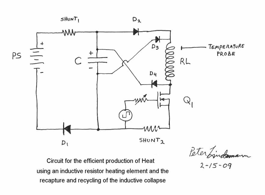
Based on the circuits and work done in the Electric Motor Secrets thread, this circuit should be easy enough to understand.
For those that do not understand it, I will describe its function in a later post.
There are broad implications connected with the proper understanding of the functions of this circuit. We all owe Rosemary Ainslie a deep debt of gratitude, both for her discoveries, and for her willingness to publish her results for the betterment of Science and the human condition.
Peter
This thread is dedicated to the heater method by Rosemary Ainslie. I hope to see some replication attempts.
I'm pasting a message from Peter that he posted in another thread below - it comes from this thread:
http://www.energeticforum.com/renewa...ld-model.html:
This is the schematic that is proven to work - USE THIS:
WATCH THIS VIDEO FIRST
YouTube - Quantum Magazine 555 Circuit Test on Rosemary Ainslie's COP 17 Heater Circuit
Tune the circuit to resonance for highest gain - it will go into high speed
self oscillation when increasing gate resistance but you need to play with
the duty cycle and frequency.
Here is a pic of what it should look like:
TAKE NOTE: The 1N4007 diode across the load inductive resistor is OPTIONAL. It shows how to get more charge back to the front battery, etc... However, the biggest gains are WITHOUT that diode. The above
schematic does NOT show the diode.
If you use the diode, you get more battery charging on the front battery
and less heat. Without, you get greatest heat and less charging on the
front battery.
------------------------------------------
This thread is full of skeptical nonsense. I always welcome questions and comments but when invalid points that are completely fabricated, false, made up, fraud, etc... WILL NOT BE TOLERATED IN THIS THREAD. They will be deleted and anyone contributing to this nonsense may be removed from the forum.
Just so you know, here are a few skeptical claims made by supposed experts:
- TK's (Tinsel Koala) claim the Quantum article timer is wrong (FACT - it works)
- TK's claim the Quantum article circuit won't oscillate (FACT - it does)
- TK's claim the oscillation is a red herring (FACT - it isn't)
- Poynt99 and Poynt's claim there is NO AC in this circuit at all (FACT - there is in the load inductive resistor)
- All claims the diode can't help charge input battery (FACT - it does)
- All claims the spikes will damage the mosfet and that the ringing should be stopped (FACT - this mosfet IRFPG50 is designed EXACTLY for this kind of application)
- All claims that the spike would be too small to be significant (FACT - on a decent circuit the voltage is 4 times the input voltage, it charges batteries or caps - it is VERY significant)
- All claims that when the mosfet is off, the battery cannot conduct and therefore won't receive a charge (FACT - the diode in the mosfet allows just this exact current conduction as it is designed to do this!)
- All claims that the spike will disappear with improved circuit connections, etc... (FACT - it only makes the spike bigger)
- All claims that the inductive resistor will change resistance as it heats up will throw off all the numbers (FACT - these resistors are made to be VERY ACCURATE at these operating temperatures. That is the whole point. They can be within 5% across a WIDE range of temperatures but the most discrepancy will be when they are extremely cold (way below ambient - or way too hot - this demonstrates the skeptics knowledge of this kind of resistor is completely lacking)
- Skeptics claim that a battery capacitance analyzer is an accurate way to determine battery capacitance for load testing and this supposedly makes the actual draw down tests unnecessary. (FACT - they are good only for sorting through batteries to see which ones need replacing or not. They are in NO WAY AT ALL - an accurate way to see what a battery will deliver.)
- When skeptics analyzed my waveform of the shunt - it was determined all the ringing was above the 0 line in the positive including the bottom half of the ringing. (FACT - The middle of the positive and amplitude of the ringing after the negative spike is in fact the zero line - and by not knowing this, they admit they don't understand how to read a waveform.)
- The skeptics claimed that the ringing cancels out any charging effect the negative spike will give. (FACT - The negative spike reduces what the battery delivers in net - the ringing down itself cancels itself out as far as battery charging ability but provides extra heat to the coil.)
- TK claimed the Quantum article schematic (posted above) will not cause the mosfet to oscillate or do anything useful for the circuit. (FACT - with the EXACT circuit from the article, I can get the mosfet to oscillate - and I have shown pics and videos)
Anyway, enjoy and make sure to look at my notes above and take that schematic and build it.
A builder's group will be posted soon...
----------------------------------------------------------------------------------
Below is a post from Peter - he brought this technology to my awareness. His circuit
below is something to be tested thoroughly after Rosemary's circuit is replicated.
Aaron,
Thanks for re-invigorating this older thread. I was about to start a new thread about Rosemary's work. I have also posted her major contributions to a new page on my site at: Free Energy | Rosemary Ainslie On this page, I have collected her papers and put them all in simple, downloadable PDF files, for ease of handling.
This material clearly shows how to build an electric heating device that produces 17 times more heat than the "equivalent" amount of electricity. It accomplishes this by using a resistive heating element that also has inductive properties, and by "recycling" the energy of the inductive collapse.
Rosemary's original test circuit is shown in the article she tried to have published in a "refereed" scientific journal, but the submission was always rejected. In the last 5 months, I have had extensive email correspondence, and numerous telephone conversations with Rosemary, who lives in South Africa. After studying her work, I was absolutely thrilled with her discovery of the super-efficient heating effect. In mid-February of this year, I proposed to her an "idealized" schematic of her DC resonance circuit to produce the effects she had discovered. That circuit diagram is here:
Based on the circuits and work done in the Electric Motor Secrets thread, this circuit should be easy enough to understand.
For those that do not understand it, I will describe its function in a later post.
There are broad implications connected with the proper understanding of the functions of this circuit. We all owe Rosemary Ainslie a deep debt of gratitude, both for her discoveries, and for her willingness to publish her results for the betterment of Science and the human condition.
Peter


")

Comment