Announcement

Collapse
No announcement yet.

Diy magnetic field scope/a scanline e-beam plane imaging tool.

Collapse
X
 
  • Filter
  • Time
  • Show
Clear All
new posts

  • Diy magnetic field scope/a scanline e-beam plane imaging tool.

    Hello to All,

    I had a few requests on my YT Chanel to upload a video showing how it is easily converted...so, this was a pending job on my Agenda...the following one is the CRT 2 Video, where we will see a FULL 360º Scanline Plane around differently excited fields, thanks to four of this Instruments.

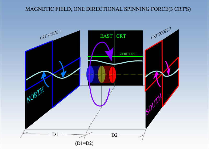
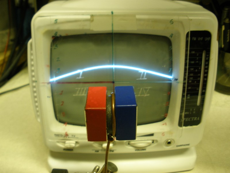
    Basically on this Thread I will be guiding anyone interested in making this awesome tool (or you could call it "Equipment" or "Instrument"..) for your Testing Lab Bench, which would help you visualize the COMPLETE MAGNETIC FIELD SPATIALLY AND THREE DIMENSIONAL TRUE GEOMETRY.

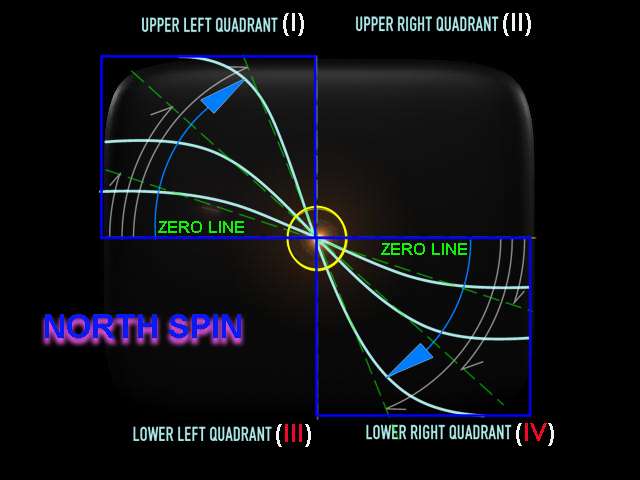
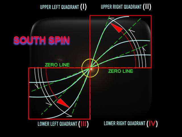
    PLUS, realize Magnetic Field DO HAVE A Directional SPIN, and NOT like it was concluded by Hendrik Lorentz long ago...that Fields were not rotational.

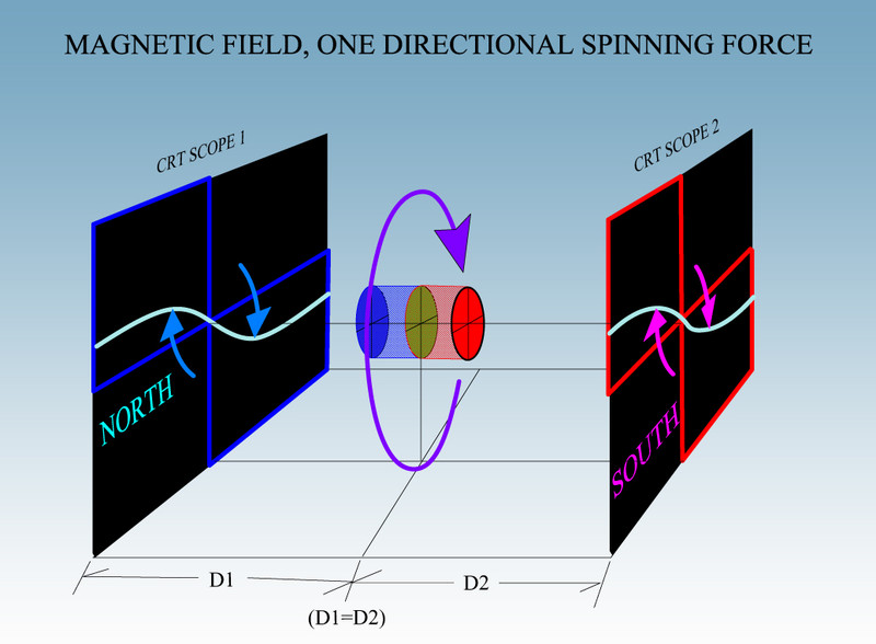
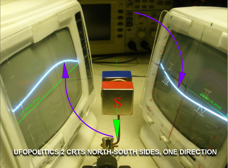
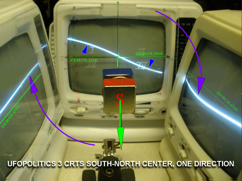
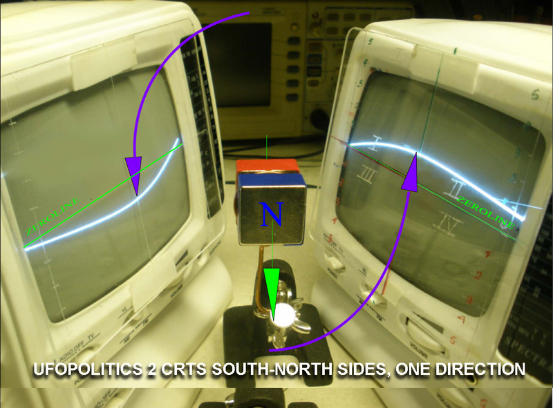
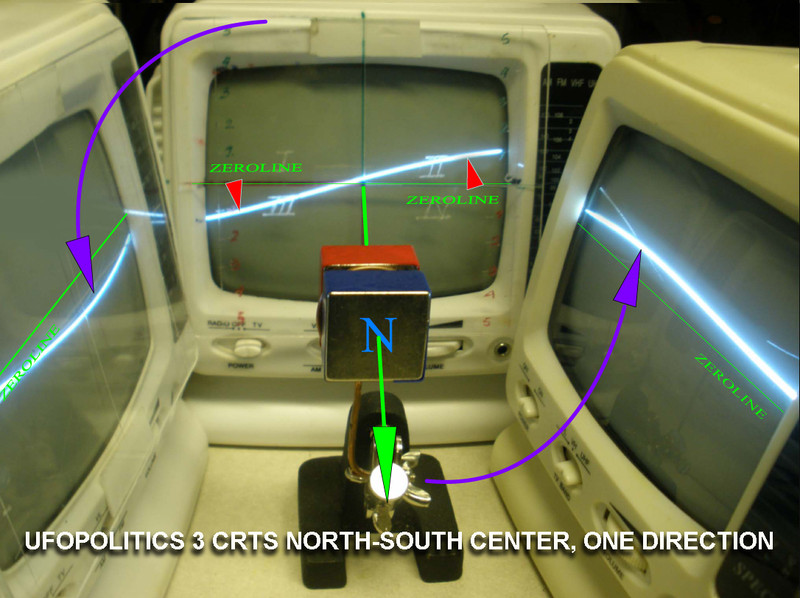
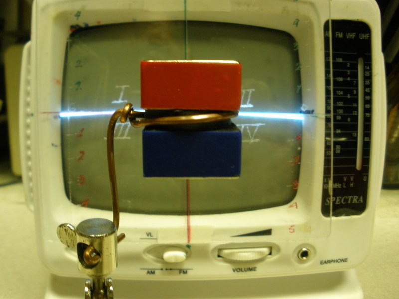
    Further on with Four of this small CRT units...and thanks to the HORIZONTAL SCANLINE ELECTRON BEAM RASTERING (SWEEPING) around whole Field...

    It will help you ALL see (in my further CRT Video) that Fields are also SPATIALLY DIVERGENT, when we all would verify it with FOUR CRT's 360º SCANLINE PLANE around ANY Magnetic Field.

    Finally, We'll all arrive to the same conclusion...that Magnetic Field Spinning Direction is just BUT ONE SINGLE SPINNING FORCE, which includes its NORTH and SOUTH POLARIZATIONS.

    Exactly as it has been stated by Ken Wheeler on his Free E-Book.

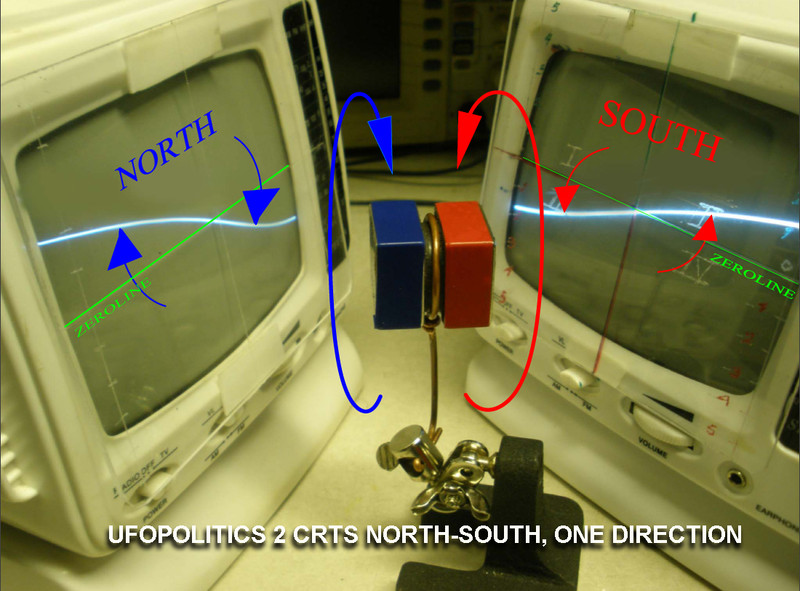
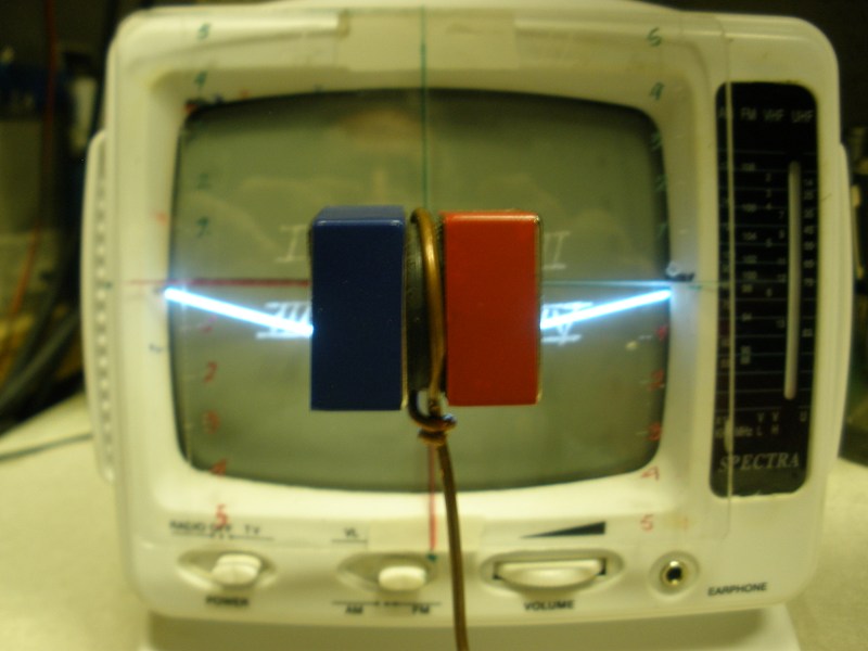
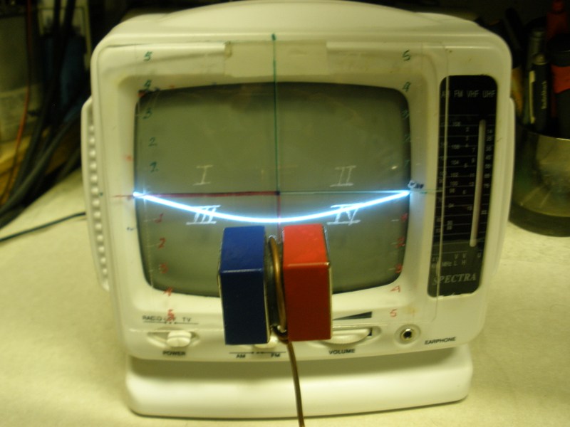
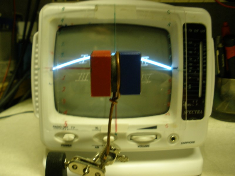
    I have put together a short video below, where I have shown how easy it is to CONVERT any (working) Analog small and old B&W CRT TV...into this awesome tool.

    [VIDEO]https://www.youtube.com/watch?v=E372P74Gq6k[/VIDEO]

    DIY MAGNETIC FIELD SCOPE

    If Anyone needs further assistance or deeper knowledge on how this small unit works...below is a MUCH DETAILED VIDEO where it is "dissected" all the way from each of the TWO MAIN DEFLECTING COILS to the electronic signals which generate the ELECTRONIC BEAM HORIZONTAL SCANLINE PLANE with all Full Color 3D Animated CAD's for easy understanding.

    [VIDEO]https://www.youtube.com/watch?v=l7OzMURRU_k&t=1370s[/VIDEO]

    CRT REVEALING MAGNETIC FIELD VORTEXES

    This Tool is HIGHLY RESPONSIVE to Electromagnets which we are pulsing-switching, whether by AC, by Square DC Positive or Negative Pulses...or a constant Reversing DC Signal, generating an ALTERNATED DC Signal.


    Regards to All


    Ufopolitics
    Last edited by Ufopolitics; 02-08-2018, 10:11 PM. Reason: rectifying caps on title
    Principles for the Development of a Complete Mind: Study the science of art. Study the art of science. Develop your senses- especially learn how to see. Realize that everything connects to everything else.― Leonardo da Vinci

  • #2
    CRT Scope/E-Beam Scanline Identifying N+S Spins

    Hello,

    The First thing this Instrument will clearly REVEAL, and ALWAYS IDENTIFY SAME WAY, is the Opposite Spin Directions between a NORTH and a SOUTH Polarization (Poles):

    NORTH SPIN SEEN ON CRT SCOPE


    SOUTH SPIN SEEN ON THE SAME CRT SCOPE SCREEN


    And this FAST AND ACCURATE RESPONSE works the same way for an ELECTROMAGNET which is being fed with direct DC Currents...Or whenever we pulse it with ANY SIGNAL we would be working with.

    Example: If we just connect our Coil to a Regulated PSU, and start dialing UP Voltage and Amperage...we will see the ANGLES WILL INCREASE, tending to reach the Vertical Line at center of screen, and perpendicular to ZERO LINE.


    Ufopolitics
    Last edited by Ufopolitics; 02-08-2018, 07:54 PM.
    Principles for the Development of a Complete Mind: Study the science of art. Study the art of science. Develop your senses- especially learn how to see. Realize that everything connects to everything else.― Leonardo da Vinci

    Comment


    • #3
      Opposite Spins=Same Rotational Direction in 3D Perspective View...

      Originally posted by Ufopolitics View Post
      Hello,

      The First thing this Instrument will clearly REVEAL, and ALWAYS IDENTIFY SAME WAY, is the Opposite Spin Directions between a NORTH and a SOUTH Polarization (Poles):

      NORTH SPIN SEEN ON CRT SCOPE


      SOUTH SPIN SEEN ON THE SAME CRT SCOPE SCREEN


      And this FAST AND ACCURATE RESPONSE works the same way for an ELECTROMAGNET which is being fed with direct DC Currents...Or whenever we pulse it with ANY SIGNAL we would be working with.

      Example: If we just connect our Coil to a Regulated PSU, and start dialing UP Voltage and Amperage...we will see the ANGLES WILL INCREASE, tending to reach the Vertical Line at center of screen, and perpendicular to ZERO LINE.


      Ufopolitics
      Even though, I have shown on my above quoted post, that a NORTH SPIN is COMPLETELY OF OPPOSITE NATURE to a SOUTH SPIN ...

      When we get TWO of this CRT SCOPES, and set them according to below CAD DIAGRAM, meaning FACE TO FACE with the FIELD IN CENTER:


      It is ONLY then, when we realize that BOTH SPINS AGREE ON SAME ROTATIONAL DIRECTION, from BOTH POLARIZATIONS...NORTH AND SOUTH.


      Regards to All


      Ufopolitics
      Principles for the Development of a Complete Mind: Study the science of art. Study the art of science. Develop your senses- especially learn how to see. Realize that everything connects to everything else.― Leonardo da Vinci

      Comment


      • #4
        Real test verification...

        Originally posted by Ufopolitics View Post
        Even though, I have shown on my above quoted post, that a NORTH SPIN is COMPLETELY OF OPPOSITE NATURE to a SOUTH SPIN ...

        When we get TWO of this CRT SCOPES, and set them according to below CAD DIAGRAM, meaning FACE TO FACE with the FIELD IN CENTER:


        It is ONLY then, when we realize that BOTH SPINS AGREE ON SAME ROTATIONAL DIRECTION, from BOTH POLARIZATIONS...NORTH AND SOUTH.


        Regards to All


        Ufopolitics

        And NOW, ...IN AN ACTUAL TEST, with Two CRT's showing exactly SAME DIRECTIONAL SPIN as seen on previous CAD Diagram...:


        Therefore, this is NOT, just about Diagrams and CAD Images...BUT THE REAL DEAL.


        Regards


        Ufopolitics
        Principles for the Development of a Complete Mind: Study the science of art. Study the art of science. Develop your senses- especially learn how to see. Realize that everything connects to everything else.― Leonardo da Vinci

        Comment


        • #5
          More Tests with Two and Three CRT's...

          Hello,

          Below are some pictures taken to a Permanent Magnetic Field REVEALING ITS DIRECTIONAL SPINS by CRT E-BEAM SCANLINES...:


          Above We are observing SOUTH Facing toward Screen, with TWO CRT's on each SIDE...can clearly see the deflections:

          LEFT CRT= ABOVE (POSITIVE) ZEROLINE
          RIGHT CRT= BELOW(NEGATIVE) ZEROLINE


          Above Image, same configuration, but now with a THIRD CRT in the BACKGROUND, Confirming the CLOCKWISE SPIN, according to FIELD POSITIONING.

          NOW LET'S SEE SAME CRT SET UP, BUT REVERSING FIELD POLARIZATIONS (POLES) BY 180º...


          Meaning, now NORTH POLE is facing Screen, so we have:

          LEFT CRT= BELOW(NEGATIVE) ZEROLINE
          RIGHT CRT=ABOVE (POSITIVE) ZEROLINE

          Completely opposite as previous setup...

          ...And below are the THREE CRT's CONFIGURATION...:


          Where SOUTH POLE is facing CENTER-BACK CRT SCREEN, and we see the TYPICAL SOUTH SPIN on CRT's Screen...


          Regards to All


          Ufopolitics
          Principles for the Development of a Complete Mind: Study the science of art. Study the art of science. Develop your senses- especially learn how to see. Realize that everything connects to everything else.― Leonardo da Vinci

          Comment


          • #6
            East-West CRT'S Scanlines...

            Hello to All,

            Basically on this post I will refer to the EAST and WEST CRT's SCANLINE Magnetic Field Views...

            EAST VIEW:


            At the center of above Image we can see the EAST CRT and we observe a completely different Electron Beam Rastered Plane (2D SCANLINE) DEFLECTION.

            The Green ZERO LINE used as reference on ALL CRT's, shows that whole deflection takes place on Both Negative Lower Quadrants, with a MUCH NEGATIVE DEFLECTION, EXACTLY at CENTER between both quadrants (Screen Center)...

            WEST VIEW:


            Above image I have kept the previous EAST VIEW CRT, (for Comparison purposes) so I had to add transparency to WEST CRT Screen...

            And so, we can see on the WEST VIEW, EXACTLY THE OPPOSITE as the Eastern View SCANLINE DEFLECTION.

            Whole WEST DEFLECTION is located in the TWO UPPER AND POSITIVE QUADRANTS.

            But with the same HIGHER POINTS ON CENTER OF SCREEN which ALIGNS exactly with Magnet's EQUATORIAL PLANE (DIELECTRIC FIELD)...except here, they are on HIGHER POSITIVE LEVELS.

            And basically, if we take a closer look at both deflections above...we will notice that if we rotate just one CRT (say EAST for example) in a 360º SPIN around Field, following its EQUATORIAL PLANE, when we reach across by 180º (where WEST CRT is set)...then we will realize that it results in exactly same deflections as seen in WEST VIEW, at just different locations of the Field.

            Other words, East and West are just relative coordinates around an EQUATORIAL PLANE which always follow SAME DIRECTIONAL SPIN...

            ON A SEPARATE NOTE, LET'S REALIZE THAT THE SCREEN SCANLINE IS JUST "A TWO DIMENSIONAL (2D) PROJECTION" ON THE FLUORESCENT SCREEN FROM THE ELECTRON BEAM CONSTANT RASTERED (SCANNED) PLANE...WHICH TAKES PLACE IN THE THREE DIMENSIONS (3D).

            Further on, I will be showing this E-Beam Plane deflections which develops in a 3D Environment within the CRT vacuum Glass Tube...just by making tube more transparent in a more advanced 3D Software CAD Program...

            Besides the obvious fact that the 3D E-Beam swept, scanned, plane, also travels OUTSIDE OF CRT Screen...to meet ALL FIELD VORTEXES...


            Regards to All


            Ufopolitics
            Last edited by Ufopolitics; 02-20-2018, 11:06 PM.
            Principles for the Development of a Complete Mind: Study the science of art. Study the art of science. Develop your senses- especially learn how to see. Realize that everything connects to everything else.― Leonardo da Vinci

            Comment


            • #7
              Backing up previous post by REAL Tested Images

              Hello,

              Here I will just BACK UP previous Post Claims with REAL TEST IMAGES, not just "painted" CAD's...

              EAST VIEWS


              ...

              WEST VIEWS


              Interesting Notes: When I am pulsing a Cylindrical Coil as an "Exciter"...with a shorter -in length- Secondary, wrapped within same core, but "movable" along the common core axis...it results very interesting that the HIGHEST AMPERAGE LEVELS are ALWAYS reached right at the VERY CENTER AREA of the Exciting and much longer Coil/Core...curiously, coinciding where we can see a MUCH HIGHER "LUMP" towards either positive or Negative Zones on CRT Deflected Scanlines (remember pos-neg or "east-west" is just a relative surface concept)...


              Regards


              Ufopolitics
              Last edited by Ufopolitics; 02-21-2018, 12:35 AM.
              Principles for the Development of a Complete Mind: Study the science of art. Study the art of science. Develop your senses- especially learn how to see. Realize that everything connects to everything else.― Leonardo da Vinci

              Comment


              • #8
                90°

                Interesting stuff Ufo,

                Please show horizontal line when magnet(s) are turned red up and blue down, centered left to right.

                Thanks in advance,

                bi

                Comment


                • #9
                  Originally posted by bistander View Post
                  Interesting stuff Ufo,
                  Thanks Bistander,

                  And I believe it would be even more interesting when I start analyzing Coils-Cores under different excitation signals...

                  Originally posted by bistander View Post
                  Please show horizontal line when magnet(s) are turned red up and blue down, centered left to right.

                  Thanks in advance,

                  bi
                  Yes, sure, I see exactly what you are suggesting...also realize it would be the same as using a Vertical Scanline-Plane (instead of Horizontal) then leaving magnet in the same position that I have before, meaning with poles axis at 90º to Scanline...correct?

                  By doing that, yes magnet poles-axis would be at 90 degrees to E-Beam Scanline... BUT, looking from the Equatorial Plane point of view (what is defined by Ken Wheeler as the Dielectric Field-Plane, which is exactly in "Counterspace") the Scanline-Plane would be perfectly aligned with this Equatorial Plane...or Parallel to it (simply put, in the same plane both)...agree on that?

                  I would post pictures later and maybe tomorrow a short video...but, based on the above facts, could you tell me first, off your thoughts, just as a guess...what would you think, the scanline deflections should look like when we align magnet that way?

                  Thanks and great test proposal from you!!


                  Regards


                  Ufopolitics
                  Last edited by Ufopolitics; 02-21-2018, 11:55 PM.
                  Principles for the Development of a Complete Mind: Study the science of art. Study the art of science. Develop your senses- especially learn how to see. Realize that everything connects to everything else.― Leonardo da Vinci

                  Comment


                  • #10
                    _____________

                    Originally posted by Ufopolitics View Post
                    ...what would you think, the scanline deflections should look like when we align magnet that way?
                    ...
                    Boring....... ______________ .

                    Comment


                    • #11
                      Scanning Dielectric Counterspace Field...

                      Originally posted by bistander View Post
                      Boring....... ______________ .
                      Exactly Bistander, just the same "boring" Flat Line...nothing happens...

                      Originally posted by bistander View Post

                      Please show horizontal line when magnet(s) are turned red up and blue down, centered left to right.

                      Thanks in advance,

                      bi


                      And it don't matter whether South or North is Up...same, exact result takes place...

                      The E-Beam Zero Scanline will not be affected at all (zero deflection) when passing PARALLEL and ALIGNED through the Dielectric Field Plane, or Equatorial Plane.

                      I have repeatedly mentioned this fact before, and it has been CLEARLY observed previously with...

                      MAGNETIC VIEW FILM

                      [IMG][/IMG]

                      And FERROCELL

                      [IMG][/IMG]

                      [IMG][/IMG]

                      This Equatorial Plane Zone is completely "inactive" from magnetism or better said, not captured within our dimension because it is taking place in Counterspace.

                      [IMG][/IMG]

                      Actually, as previously written by K. Wheeler, this is where magnetism returns back as also emanates from its origin, Aether, which is in Counterspace.

                      If you have one of this CRT Scanline Tools, then you could see how THIN is this Plane, where a minimal, slight turn of the Magnet Axis, will rapidly start showing either North or South Spinning Patterns, depending on the tilting direction of the very narrow angle.

                      Surprised with results?...Were you expecting other deflection's Patterns here?...please share your thoughts...

                      On the other hand, as seen on iron filings views of the Magnetic Field...where there is "no center" shown, but straight lines crossing between both poles (heavy "traffic"), then E-Beam should reflect -at least- some "activity" in your suggested 90º position...don't you think?


                      Regards


                      Ufopolitics
                      Last edited by Ufopolitics; 02-22-2018, 02:49 PM.
                      Principles for the Development of a Complete Mind: Study the science of art. Study the art of science. Develop your senses- especially learn how to see. Realize that everything connects to everything else.― Leonardo da Vinci

                      Comment


                      • #12
                        Thanks for running the test

                        Originally posted by Ufopolitics View Post
                        ...

                        The E-Beam Zero Scanline will not be affected at all (zero deflection) when passing PARALLEL and ALIGNED through the Dielectric Field Plane, or Equatorial Plane.
                        ...
                        This Equatorial Plane Zone is completely "inactive" from magnetism or better said, not captured within our dimension because it is taking place in Counterspace.
                        ...
                        Why then is there maximum deflection of the scan line in that zone in the test here?

                        Originally posted by Ufopolitics View Post
                        Next question:
                        Originally posted by Ufopolitics View Post
                        ...
                        On the other hand, as seen on iron filings views of the Magnetic Field...where there is "no center" shown, but straight lines crossing between both poles (heavy "traffic"), then E-Beam should reflect -at least- some "activity" in your suggested 90º position...don't you think?
                        No, because the lines of flux are perpendicular to the beam so the resulting forces on the charges (electrons) are parallel to the scanline, so do not deflect it.

                        Thanks again for the test.

                        bi

                        Comment


                        • #13
                          Originally posted by bistander View Post
                          Why then is there maximum deflection of the scan line in that zone in the test here?


                          I knew you were gonna ask about this...

                          It is simple Bistander, in above settings the E-Beam Scanline Plane is PERPENDICULAR to the Dielectric Field Plane, therefore, both planes only INTERSECT at a center point, or line if we are talking about planes 3D...what I mean here is that Dielectric/Scanline Planes Intersection is reduced to a THIN LINE or a POINT on Screen...whichever way you wanna look at this... 2D or 3D...

                          While majority of magnetic forces from both polarizations (N-S) are EMANATING right from very CENTER area of magnet to DIVERT IN A SPIN towards each Spatial End Area in a 3D Curve which keeps pushing the Scanline Plane in the Spinning Direction of the whole Field (Both Poles Forcing plane in same direction), in above image we are seeing BOTH POLES SPINNING FORCES, in the same direction PUSHING Scanline Plane UPWARDS to top of screen.

                          Why HIGHER Deflection at Center of Screen?...simple, because there are exactly TWO FORCES PUSHING right at center Scanline Plane, while also DIVERGING (Splitting) away as well, which actually fades out forces as it turns in 3D away from screen TOWARDS both opposite ends, just like any curvy-linear or Torsion Force acts in SPACE, except here we have Dual Torsion Forces plus diverging (fading) away to both ends...

                          Originally posted by bistander View Post
                          Next question:

                          No, because the lines of flux are perpendicular to the beam so the resulting forces on the charges (electrons) are parallel to the scanline, so do not deflect it.

                          Thanks again for the test.

                          bi
                          As you have noticed from all previous CRT images...this Electron Beam Scanline reveals perfectly well when it is precisely aligned in a PERPENDICULAR Fashion to the Field Planes/Axis (lines).

                          First when we project Magnetic Field Poles AXIS, where Spin REVOLVES in a 3D Plane, which is exactly Perpendicular to the Scanline Plane...then we clearly see each pole spinning direction.

                          Second, and as you have shown above...whenever the Scanline Plane is Perpendicular to the Dielectric Plane.

                          Third, in your proposed test Dielectric Plane was PARALLEL to Scanline Plane...so, no go, nothing, boring right?

                          Now, I agree that in order to fully understand what I am writing above...basically answering your first question, I will have to build the whole model in 3D View, where I show the Three Dimensional Curvatures coming out from center plane and flowing towards opposite extremes (Divergence) of the Magnetic Field Polarizations...while showing a Full 3D Scanline Plane on CRT only...without any black and opaque tube, but mainly the E-Beam Rastered Plane being TWISTED by the Magnetic Spinning Forces...

                          ..and I will eventually do that further on...it must be on a video to capture the 3D Views plus animated dynamics of both 3d curvy-linear flows...


                          EDIT: We have to realize that this Magnetic Spatial Spins are PARTIAL
                          , and NOT fully 360º and continuous spins...otherwise we would have Free Energy by far and long time ago...plus MPM, etc,etc...Reason why we have to physically advance or retract magnetic embodiments in space to observe induction, so that these Partially aligned spins enter the induced coils and push an electron flow in a steady fashion...

                          Ken Wheeler did a beautiful work on this Spatial Curves Geometry where he concluded with a specific SEPARATION AND INCLINATION ANGLE in between each spin curved vector...


                          Regards


                          Ufopolitics
                          Last edited by Ufopolitics; 02-22-2018, 06:10 PM.
                          Principles for the Development of a Complete Mind: Study the science of art. Study the art of science. Develop your senses- especially learn how to see. Realize that everything connects to everything else.― Leonardo da Vinci

                          Comment


                          • #14
                            O.K.

                            Originally posted by Ufopolitics View Post
                            I knew you were gonna ask about this...

                            It is simple Bistander, in above settings the E-Beam Scanline Plane is PERPENDICULAR to the Dielectric Field Plane, therefore, both planes only INTERSECT at a center point, or line if we are talking about planes 3D...what I mean here is that Dielectric/Scanline Planes Intersection is reduced to a THIN LINE or a POINT on Screen...whichever way you wanna look at this... 2D or 3D...

                            While majority of magnetic forces from both polarizations (N-S) are EMANATING right from very CENTER area of magnet to DIVERT IN A SPIN towards each Spatial End Area in a 3D Curve which keeps pushing the Scanline Plane in the Spinning Direction of the whole Field (Both Poles Forcing plane in same direction), in above image we are seeing BOTH POLES SPINNING FORCES, in the same direction PUSHING Scanline Plane UPWARDS to top of screen.

                            Why HIGHER Deflection at Center of Screen?...simple, because there are exactly TWO FORCES PUSHING right at center Scanline Plane, while also DIVERGING (Splitting) away as well, which actually fades out forces as it turns in 3D away from screen TOWARDS both opposite ends, just like any curvy-linear or Torsion Force acts in SPACE, except here we have Dual Torsion Forces plus diverging (fading) away to both ends...
                            ...
                            Hi Ufo,

                            I don't buy it. I think you're grasping for straws. There is no "dielectric field plane" or "equatorial plane". But that's your story, so carry on.

                            Regards,

                            bi

                            Comment


                            • #15
                              Originally posted by bistander View Post
                              Hi Ufo,

                              I don't buy it. I think you're grasping for straws. There is no "dielectric field plane" or "equatorial plane". But that's your story, so carry on.

                              Regards,

                              bi
                              Bistander, and am NOT selling nada...
                              You asked me about a test, and I did so, plus I knew your requested test was not to discuss in a normal way, but end it up in your typical disagreement fashion...
                              Now, how do you EXPLAIN EACH POLARIZATIONS OPPOSITE SPIN CLEARLY SHOWN?
                              PLUS demonstration of ONE FORCE SPIN when incorporated into 3D?
                              Do NOT wanna talk about that part huh?

                              I will end up saying THIS IS NOT ALL...NOT FINISHED YET, BUT JUST STARTING UP.


                              Take care


                              Ufopolitics
                              Principles for the Development of a Complete Mind: Study the science of art. Study the art of science. Develop your senses- especially learn how to see. Realize that everything connects to everything else.― Leonardo da Vinci

                              Comment

                              Working...
                              X