 Tweet
Tweet
Hi Pals,
Since this might be different from the thread about the Lockridge's device as envisionned by our friend and mentor Peter Lindemann, I'm opening this new thread as an alternative path.
I'm currently wondering if the Lockridge device could have been a double Werner von Siemens device with a capacitor in the middle...
See here why, and please feel free to give your opinion :
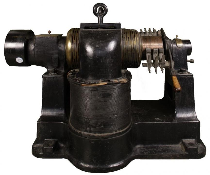
https://www.siemens.com/history/en/n...principles.htm
Here is an an "exploded view diagram" :

Thanks.
Since this might be different from the thread about the Lockridge's device as envisionned by our friend and mentor Peter Lindemann, I'm opening this new thread as an alternative path.
I'm currently wondering if the Lockridge device could have been a double Werner von Siemens device with a capacitor in the middle...
See here why, and please feel free to give your opinion :
https://www.siemens.com/history/en/n...principles.htm
Here is an an "exploded view diagram" :
Thanks.
 , and more : it was a severe war time and zone).


Comment