 Tweet
Tweet
Post 1 - Left Blank
-
-
Expecting the day to come, I kept my single comm write ups mostly in just two posts on the 'My Asymmetric Electrodynamic Machines' thread. There is some early stuff remaining there which predates the following information, but it is not critical to the continued analysis of the Single Commutator Hybrid Symmetric-Asymmetric DC Motor...the SC series.
Post 1 is blank should there be any information which I want to distill from the thread in the future.
The following two posts are lifted, unedited from 'My Asymmetric Electrodynamic Machines'.Last edited by HuntingRoss; 05-31-2015, 08:09 PM. -
Hi to everyone. I've been quiet but not inactive. I submit for peer review, the SC#5.
Schematic at the end of this post and photos to follow shortly.
The OEM motor -
MY6812 24v 120w
12 poll 2 stator 1 commutator 2 brushes
0.53mm guage wire
A symmetrical motor has one length of wire wound with coils in series, the wire returning to the origin.
The route for current is one direction along two paths from brush to brush. If you picture the brushes at 3 and 9 o'clock, path 1 passes through 12 o'clock and path 2 passes through 6 o'clock.
This embodiement retains the original structures of the OEM replacing only the wire and adding 2 brushes.
--S--
Title explained -
The SC#5 (single commutator build 5) embodies the symmetric principle with one wire wound in coils in series returning to the origin. It departs from the principle as only 2no commutator sectors are so wired. The remaining comm sectors are wound as independent pairs giving a total of 6no pairs.
In this way pairs are isolated after leaving their Motor brushes and are free to deliver their energy to the Generator
brushes just prior to being re-energised 180o advanced.
For this reason I have retained the description Asymmetric and hence HYBRID.
--S--
Winding.
3 coil groups in pairs. 11 turns 3 poles per coil of 0.5mm wire. Wound for CW rotation.
Starting with P1 at 9 o'clock. Moving clockwise wind for north coil repulsion 3 coil groups. On completion of the first 3 coils hook over P7 comm and still moving clockwise wind another 3 coil groups (all coils are wound clockwise as seen from the front with shaft seen behind the coil). On completion of the second 3 coils hook over P1 comm and twist the two ends together tightening against the P1 tab. If this is not clear in the description, schematic below should help. This is one Pair of 3 coil groups.
Pairs are as follow -
P1 / P7
P4 / P10 (P4 is perpendicular to P1)
P2 / P8
P5 / P11 (P5 is perpendicular to P2)
P3 / P9
P6 / P12 (P6 is perpendicular to P3)
This winding pattern gives a very 'flat' build, meaning the build up of wire towards the commutator is minimised and wire length is more balanced around the armature as the wind progresses.
The coils on the 12 o'clock side energise North and the coils on the 6 o'clock side energise South. Both are in repulsion to their stators.
The geometry of the 12 pole motor places the P1 Coil 1 bisector approximately 20o past the north stator bisector. The geometry of this motor doesn't allow for that figure to be greatly reduced. Reduction is crudely adjusted depending on poles grabbed per coil. Finer tuning would require re-engineering of the brush mounting plate.
I tested each pair after winding at 5v PSU and measured amps -
Pair 1 - 1.92A
Pair 2 - 2.46A
Pair 3 - 2.44A
Pair 4 - 2.41A
Pair 5 - 2.38A
Pair 6 - 2.09A
A feel (literally) for torque was assessed with each pair by pinching the shaft between my fingers and I was surprised from
coil one onwards the reluctance for the motor to stall.
Bench test SC#5 -
5v @ 2.09A @ 2700rpm rising to 2800rpm
10v @ 2.30A @ 6048rpm
Bench test OEM -
5v @ 1.18A @ 763rpm
10v @ 1.18A @ 1546rpm
--S--
Static Scooter tests :
The motors were plugged into the controller only. Not driving the rear wheel.
SC#5 -
25.1v @ 3.6A @ 13,128rpm (90.4W)
OEM -
25.1v @ 0.88A @ 3840rpm (22W)
With the scooter tethered to a static object (washing machine) with a scale balance -
SC#5 5.7kg
OEM 8.525kg
This is in effect a static stall torque test measured at the radius of the wheel.
Findings -
The static test places the SC#5 at 70% of the OEM torque.
The 5v, 10v and 24v tests places the SC#5 at around 3-4x the revs and 2x the amps.
The motor drives the back wheel through final gearing. The shaft sprocket is a 16 tooth the wheel sprocket is 88 tooth giving
5.5:1. The OEM no load free spinning speed is 640rpm.
--S--
Adding Brushes -
The OEM brush holders are brass with 4no tab feet bent under the mounting board. My donor motor was stripped of its brushes and I drilled and mounted into the SC#5.
As the repulsion coils rotate off their Motor brushes the collapsing north and south coils continue to repel but become increasingly attracted to their opposite magnet. Positioning the Generator brushes is set to allow the incoming attractive coils to assist rotation for as long as possible, accordingly they are set at P3 and P9.
Bench test V out -
5.4v PSU no load
5.02v in @ 2.32A. 3.89v out @ 2706rpm
10.28v PSU no load
9.93v in @ 2.49A. 9.93v out @ 5919rpm
The additional brushes added some load / resistance. These figures settle a little outwith the snapshot of testing.
--S--
Running a load off the SC#5 output -
5.38v PSU
SC#5 4.94v @ 2.28A @ 2692rpm (11.3w) @ 3.69v out
Connect OEM load to SC#5 output
SC#5 4.96v @ 2.47A @ 2644rpm (12.3w) @ 3.33v out
OEM 3.33v @ 0.5A @ 475rpm (1.7w)
10.33v PSU
SC#5 9.96v @ 2.35A @ 5870rpm (23.4w) @ 7.82v out
Connect OEM load to SC#5 output
SC#5 9.89v @ 2.51A @ 5923rm (24.8w) @ 7.43v out
OEM 7.43v @ 0.78A (5.8w) @ 1115rpm
(note: the motor was warming and the 5870rpm had risen to above 6000rpm)
Scooter 24v batteries and controller -
OEM 120w : 25.1v @ 0.88A @ 3840rpm (22W)
OEM 450w geared motor connected to controller : 24v @ 2.63A @ 471rpm (63W)
(note: reference to OEM in all other cases is OEM 120w motor described at the top of this post)
SC#5 24v @ 3.55A @ 13,025rpm (85.2w) @ 13.5v out
Connect OEM 120w load to SC#5 output
13.5v @ 0.93A @ 1990rpm (12.6W)
Connect OEM 450w geared motor load to SC#5 output
13.5v @ 2.33A @ 242rpm (31.5W)
Despite the power hungry nature of SC#5 I'm interested to see that 31W was returned at the output. I will need to rig the twist grip on the scooter to free up my hands for testing the change in performance of the SC#5 when the load is added. From the 5v and 10v results the difference may be very small and this would be a significant use to balance the disparity between the OEM and SC#5 current draw.
--S--
THEORY.
The shortfall in SC#5 torque at 24v can be adjusted by varying the final drive ratio to bring it up to the OEM benchmark and thereby trading revs for torque.
The OEM @ 24v @ 3840rpm @ 5.5:1 delivers 640rpm at the wheel. (assuming some frictional losses)
If the SC#5 @ 10v @ 6000rpm were to deliver 640rpm at the wheel the final drive ratio would be 6000/640 = 9.3:1
With a 16 tooth drive gear the final sprocket would be 16x9.3 = 149 teeth @ 3mm pitch = 447mm belt = 142mm dia.
The scooter wheel is a standard 5.5" 138mm dia so a gearing compromise would be required.
Assume 5" 127mm dia = 400mm circumference @ 3mm pitch = 133 teeth : 16 = 8:1 final drive = 750rpm
In theory then, modifying the 88 tooth sprocket to 133 tooth, the SC#5 might match the OEM torque and have a minor advantage in revs @ 10v (not 24v).
However I think the gearing adjustment will only compensate at 24v in which case there is a large rev differential which is likely to be a troublesome feature within a small scooter platform.
The more likely conclusion is the 13k revs @ 90watts (no load) will benefit from significant gearing down to raise the torque for a larger diameter wheel.
Otherwise it is hard to justify 90W as a starting point compared to the OEM's 22W although getting 31w or more on the output is useful compensation.
--S--
Proposed Field Tests.
Once I have modified the rear sprocket the 2no 12v batteries connected in series will be wired in parallel and the SC#5 will be tested against the OEM for speed and endurance @ 12v.
Happy Hunting
mark
[IMG]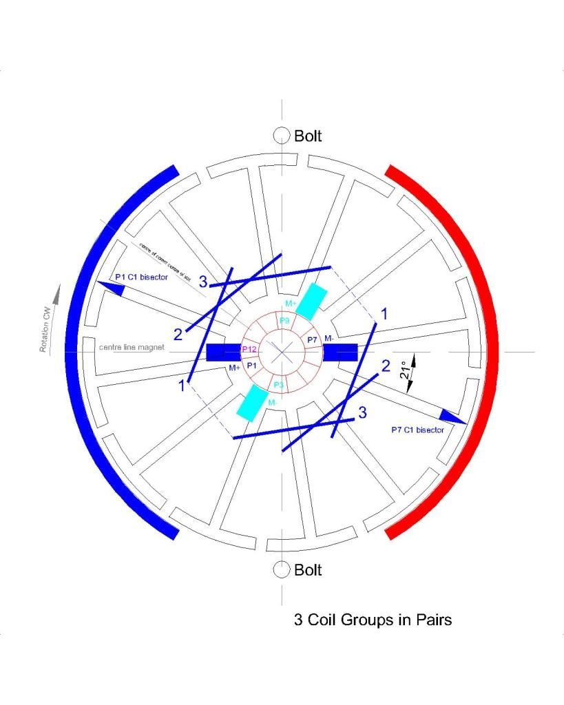 [/IMG]
[edit: Try as one does to get things correct...The schematic should show the P7 coils in red]
--S--
26th Feb 2015 - Photo upload
[IMG]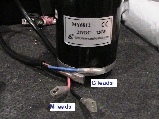 [/IMG]
[IMG]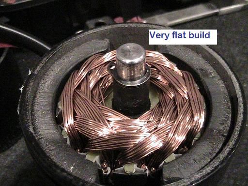 [/IMG]
[IMG]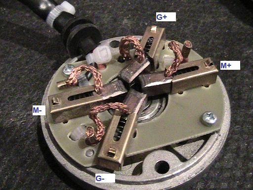 [/IMG]
[IMG]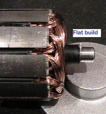 [/IMG]
[IMG]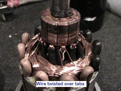 [/IMG]
--S--
28th Feb 2015 - SC#6 Build and Test Results
So today I chopped one new OEM and wound it as follows -
3 - 4 pole coil groups in Pairs - 20 turns per coil of 0.425mm wire. Schematic and photos to follow. Scooter torque test tomorrow.
Something as simple as organising the pairs as described at the top of this post allows me to easily get an extra 4 turns per coil over my previous 16 which was a struggle.
Results -
5.39v PSU no load
5.05v @ 1.33A @ 1713rpm. (6.72w). Vout 4.79v
10.35v PSU no load
10.23v @ 1.48A @ 3554rpm. (15.14w). Vout 10.44v [Note. I double checked that result - the Vout exceeds the Vin]
--S--
Curious with the increase in voltage I just completed a load test -
10.36v PSU no load
SC#6 ~ 10.14v @ 1.5A @ 3402rpm @ 10.51 Vout [15.2w]
Connect SC#5 to SC#6 Vout
SC#6 ~ 9.92v @ 2.80A @ 3071rpm @ 8.36 Vout [27.78w]
SC#5 ~ 8.36v @ 1.84A @ 4803rpm [15.38w]
Allowing SC#5 to warm up
SC#5 ~ 8.36v @ 1.60A @ 4810rpm [13.38w]
SC#6 running no load @ 15.2w rising by 12.58w under load which is less than the power being used by SC#5. Perhaps someone can explain that. I will check this again tomorrow when I conclude the scooter torque test.
--S--
29th Feb 2015 - Static Scooter Test, Output load tests and photo of build.
26.5v @ the scooter controller output.
SC#6 ~ 24.7v @ 2.13A @ 8506rpm @ 26.6v out [52.6W] No load
Connect SC#5 to SC#6 output
SC#6 ~ 23.5v @ 3.87A @ 8015rpm @ 26-40v out [90.95W] The output was fluctuating a lot, this doesn't happen with the OEM. A scope of this output would be interesting.
SC#5 ~ 26-40v @ 2.52A @ 10,878rpm [notional watts 65W]
Connect OEM 450W to SC#6 output
SC#6 ~ 23.5v @ 4.09A @ 8054rpm @ 22.2v out [96.1W]
OEM 450w ~ 222.2v @ 2.62A @ 442rpm [58.16W]
Once again the SC#6 under load takes less power than the SC#6 no load + SC#5 load. Does anyone have a theory on this ?
Notice also the OEM 450w pulling 58W compared to SC#5 load @ 31W.
SC#6 static pull (torque) test 5.9kg (OEM 8.8kg)
[IMG]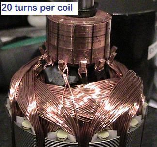 [/IMG]
--S--
[IMG]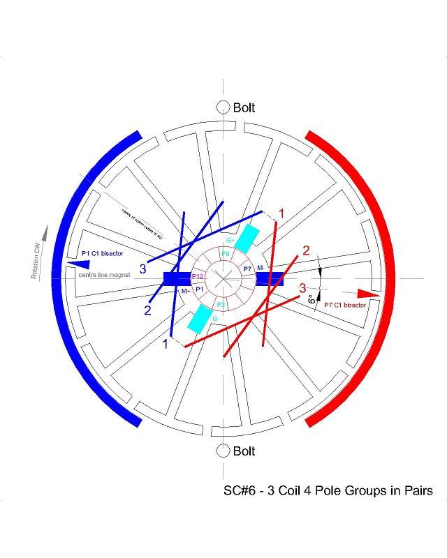 [/IMG]
--S--
2nd March 2015 - SC#7 build commenced. 3 coil 5 pole groups in Pairs - 20 turns per coil. Test results for pairs as build progresses -
Pair 1 - 5.21v @ 1.0A @ 934rpm
Pair 2 - 5.14v @ 0.98A @ 1150rpm
---S---Last edited by HuntingRoss; 05-31-2015, 08:10 PM.Comment
-
SC#7 Build and Tests
3 coil 5 pole groups in Pairs. 20 turns per coil @ 0.425mm wire. Schematic at the bottom and photos to follow.
This is bordeline to not being able to complete. The last coil of one group overlaps the first coil of the other group causing a bump. This is compounded by the 5 pole coils cross the horizon of the shaft causing the wires to stack at the centre of the rotor. This makes the wires rise quickly at the centre making it difficult to avoid the commutator and the final coils are too level with the tabs to make an easy contact. I was just able to complete the wind at 20 turns per coil but had to devise a way to prevent the coils from falling out of the slots. I bound the wires in place by cotton thread by winding around the poles and thereby jumping from pole to pole at the top and bottom of the armature.
5.38v PSU no load
SC#7 - 5.06v @ 1.15A @ 1197rpm @ 3.75v out (5.82W)
Connect SC#5 to SC#7 output
SC#7 - 4.97v @ 1.98A @ 932rpm @ 1.82v out (9.84W)
SC#5 - 1.82v @ 1.50A @ 684rpm (2.73W)
Connect OEM 450W to SC#7 output
SC#7 - 4.97v @ 2.04A @ 932rpm @ 1.75v out (10.14W)
450W - 1.75v @ 1.48A @ 26rpm (2.59W)
10.35v PSU no load
SC#7 - 10.24v @ 1.10A @ 2676rpm @ 8.49v out (11.26W)
Connect SC#5 to SC#7 output
SC#7 - 10.08v @ 2.21A @ 2429rpm @ 6.35v out (22.28W)
SC#5 - 6.35v @ 1.73A @ 3478rpm (10.99W)
Connect OEM 450W to SC#7 output
SC#7 - 10.09v @ 2.21A @ 2461rpm @ 6.37v out (22.30W)
450W - 6.37v @ 1.63A @ 118rpm (10.38W)
25.7v scooter controller no load
SC#7 - 24.9v @ 1.59A @ 6772rpm @ 20.9v out (39.59W)
Connect SC#5 to SC#7 output
SC#7 - 24.1v @ 3.07A @ 6448rpm @ 24v out (fluctuating)
SC#5 - 24v varies @ 2.53A @ 9165rm
Connect OEM 450W to SC#7 output
SC#7 - 24.1v @ 3.17A @ 6486rpm @ 17.9v out (76.40W)
450W - 17.9v @ 2.21A @ 351rpm (39.56W)
Scooter no load rear wheel 1149rpm
Tether test 7.5kg 88% (approaching the OEM 8.5kg)
[IMG]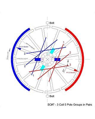 [/IMG]
--S--
So, it's been bothering me how to compare different motor configurations. Some dismiss themselves but many have certain qualities which look like they may be useful. I've started to express outputs in Watts because the Volts/Amps readings vary wildly sometimes. But that still doesn't crystalise it for me.
Now this may not be new, it may even be flawed, but the following does seem to bring a certain sense to the process.
For me a motor must possess torque for the least expenditure of power to set itself above its competitors. As a baseline they must equal or better the OEM.
(apologies if this doesn't tabulate very well - also I will call my static tether test 'torque' as it is a basis to compare the strength of motors by simply hitching it to a spring balance expressed in Kg.)
24v motor tests :
OEM~1.13A~3840rpm~27W~8.8kg
SC5~3.60A~13128rpm~90W~5.7kg
SC6~2.13A~8506rpm~53W~5.9kg
SC7~1.59A~6772rpm~40W~7.5kg
Expressing all of that as a percentage of the OEM :
OEM~100%A~100%rpm~100%W~100%kg
SC5~318%A~342%rpm~333%W~65%kg
SC6~188%A~221%rpm~196%W~67%kg
SC7~140%A~176%rpm~148%W~85%kg
And for simple maths if a motor doubled the Watts and doubled the RPM then the nett result would be comparable to the OEM and would be expressed as %RPM divided by %Watts (%RPM/%W) which would equal One (1) in this example. If the result is more than 1 there is a nett advantage over the OEM.
So for the above :
SC5~342/333=1.03
SC6~221/196=1.13
SC7~176/148=1.19
That puts SC7 ahead of the OEM as the RPM increased more than the Watts but this doesn't consider all three motors are under torque.
With gearing the revs can be turned into torque. For example, halve the revs to double the torque. Assuming there is no change to the Watts, then :
SC5 needs to be geared by 54%, SC6 by 49% and SC7 by 18%
Applying those percentages to the motors will bring the revs down and bring the torque up to 100% :
SC5~8525rpm
SC6~5701rpm
SC7~5758rpm
OEM~100%A~100%rpm~100%W~100%kg
SC5~318%A~222%rpm~333%W~100%kg
SC6~188%A~148%rpm~196%W~100%kg
SC7~140%A~150%rpm~148%W~100%kg
%RPM/%W :
SC5~0.67
SC6~0.76
SC7~1.01
On a strictly theoretical analysis of the figures, SC7 can be geared to compensate for the shortfall in torque and the remaining RPM advantage is not gained by excessive power draw.Last edited by HuntingRoss; 05-31-2015, 08:11 PM.Comment
-
Since SC7, I have been busy with SC8 and SC9. Mostly useless and I'll maybe describe them one day. SC10 being a derivation of SC6 and SC11 being a derivation of SC7.
My primary focus is the torque testing of these motors to ascertain the amount of work they are likely to deliver. My early tests of Volts Amps Revs do not reveal the true nature of the Beast.
I will be bringing the test results for SC11, SC11.1 and SC11.2 over the next day or so in comparison to the OEM and SC7.
Happy Hunting
markLast edited by HuntingRoss; 05-31-2015, 09:00 PM.Comment
-
A baseline for testing all SC models has been the OEM 'MY6812' motor which has a 24v rated torque of 42 Ncm.
The following torque results were taken off my Prony rig at 10v PSU -
OEM - (12no 5 pole coils in series @ 23 turns per coil @ 0.53mm wire) 25.27 Ncm @ 40.26 W in @ 704 rpm.
SC7 - (3 coil 5 pole groups in Pairs @ 20 turns per coil @ 0.425mm wire) 28.18 Ncm @ 75.35 W in @ 707 rpm.
SC11 - (4 coil 5 pole groups in Pairs @ 17 turns per coil @ 0.425mm wire) 32.35 Ncm @ 77.07 W in @ 528 rpm.
SC11.1 - (4 coil 5 pole groups in Pairs @ 12 turns per coil @ OEM 0.53mm salvaged wire) 36.20 Ncm @ 133.32 W in @ 1219 rpm.
SC11.2 - (4 coil 5 pole groups in Pairs @ 11 turns per coil @ 0.53mm wire) 38.78 Ncm @ 151.59 W in @ 1248 rpm.
SC11.2 at 10v is a cats whisker behind the OEM rated torque of 42 Ncm at 24v but is taking an extra 110 W to achieve it.
The next stage is to road test and see if throttle control alone will produce the correct mix of torque, speed and power consumption.
Keep Hunting
markComment
-
Moving from 3 coil groups to 4 coil groups was to achieve better resistance and better attraction. This makes the angle between the first and last coil bisectors 90�.
Moving that up to 5 coil groups suffers the same fate as the '4 pole Pairs' debate where the angle increases to 120� and consequently the energised coils pass the SSB...equals not good.
As a simple design modification the impact on torque is dramatic. Compare SC7 to SC11, 28 Ncm vs 32 Ncm. The watts in is negligble difference.
Increasing the wire size from SC11 to SC11.1 and 2 was an exercise in curiosity. The watts go up but the motor is nearly achieving OEM standard at less than half the volts.
Happy Hunting
markComment
-
Hey Mark,
Check this guy out, that made that Single Commutator, with independent coils motor back in 2011...
And he obtained excellent results...except higher amp draw at no load.
[VIDEO]https://www.youtube.com/watch?v=Q9CLtlkl6fM[/VIDEO]
It was originally introduced by Bob Smith about a year ago on a Thread to discuss the winding type:
NEW MOTOR WINDING ARRANGEMENT
You may find interesting comments there as well.
Enjoy and great luck with your new Thread
UfopoliticsLast edited by Ufopolitics; 06-02-2015, 03:18 PM.Principles for the Development of a Complete Mind: Study the science of art. Study the art of science. Develop your senses- especially learn how to see. Realize that everything connects to everything else.― Leonardo da VinciComment
-
Thanks UFO
Isn't that weird. I watched that video years ago and had no idea what it was all about. Now I watch it and understand perfectly.
When the time is right, it makes sense...until then...nothing.
The Bob Smith thread has some useful comments...especially on the pulse theory of input and output through a wound stator. I'll save that build for a rainy day.
Happy Hunting
markComment
-
An interesting difference in that re-wind of the compressor motor and the way I wind my single comm motors is...
The compressor is wound from one end 'north on the face' to the next coil 'south on the face' to the end.
My method is to wind all 'north on the face' and in effect connect at both mid points.
('on the face' meaning as you look at the rotor)
There is no practical difference except my tabs start and finish with two wires (hence mid points) and his starts and finishes with one wire (hence end points).
On balance I prefer my method because one tab is just hooked over and the starting point is twisted to tighten against the tab. This is useful when you're doing a lot of chops to designs on one rotor because it saves fatigue on the tabs.
Happy Hunting
markComment
-
Originally posted by HuntingRoss View Post
Ok, so you are winding each matching coil (180� apart) both projecting outwards the North Fields, hence south towards shaft..
And the way you connect them to comm tabs is in Parallel, not in series like he did...so you have two wires per tab.
Is the way I am figuring it out...
Parallel winding will bring some higher amps...but a lot of torque.
UfopoliticsPrinciples for the Development of a Complete Mind: Study the science of art. Study the art of science. Develop your senses- especially learn how to see. Realize that everything connects to everything else.― Leonardo da VinciComment
-
Hi UFOOriginally posted by Ufopolitics View Post
Yes to the parallel part...
Looking at the side of the rotor (face on)
I wind north from P1 to P7 (P1 on the right, P7 on the left)
Loop over P7
Then wind north from P7 to P1 (P7 on the right, P1 on the left)
Or to put it another way...
Looking on the top of the rotor
I start at P1 on the right and wind north
Each successive coil progresses CW until you come back to P1.
So one side fires up north, the other south...
Happy Hunting
markComment
-
Ross,Originally posted by HuntingRoss View Post
Yeah, I watched that video years ago also. Just like you, I finally understand it now. That Russian man used the independent singular coils hybrid in 2011. It's all just recycled information with a twist... Series, parallel, pairs, groups, singular coils, one commutator, two commutator... If it was done in 2011, I'm pretty sure it was done way before hit hit the forums.... Nothing new under the sun. ... Like most people, we just didn't know any better.
Have you found anything yet about the 3pole sc motors yet?
I read and reread B Smiths thread. Brown is really knowledge! Here's my favorite part.
Originally posted by mbrownn View Post
MidazLast edited by Midaztouch; 06-03-2015, 04:28 AM.Comment
-
Not a sausage.Originally posted by Midaztouch View Post
Any way you look at it, it's really a bad example of a single comm concept.
No down time to speak of and no extra brushes.
Its uses would be very limited.
On a side note. The test pilot has been booked for the weekend...count down to rain.
Happy Hunting
markComment
-
Ross,Originally posted by HuntingRoss View Post
On the SC11.2, why did you decide to use one less turn per coil? What was the ohms differance between 11 & 12turns?
You used one less turn and the RPMs went up... but the torque increased over the 12turns, also??
If you have time, could you explain that for me?
MidazLast edited by Midaztouch; 06-04-2015, 01:09 AM.Comment


Comment