 Tweet
Tweet
Dear Forum,
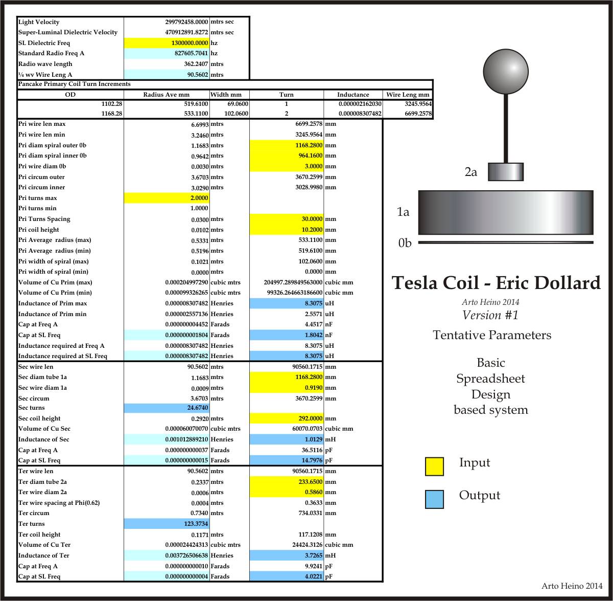
I build a spreadsheet to simplify calculations that Eric provided for building a Cosmic Induction Generator (CIG).
I was puzzled but not surprised when his calculations came up way different than JavaTC.
After a bit of messing around I realised they roughly equal the calculated resonant frequency devided by 1 over 2pi.
For example Eric provided the dimensions for a 1mhz coil. JavaTC calculates the resonant frequency to be 1.467mhz.
1.467�(1�2pi) = 0.93392mhz
I also did the same calculation using a 20% and 50% primary height with 62% and 10% spacing. The answers were all about 10% out.
So my question is: what causes these figures to be so different than they should be?
A coiled wire will not have the same resonant frequency as a straight one of the same length.
According to JavaTC and my own experience building coils the coil will work poorly using these plans.
As the primary will oscillate at 1mhz the secondary at 1.4mhz will be 40% detuned.
So is Eric saying his coil is not a air core resonant transformer with frequency matched coils? If not what principle does it operate by?
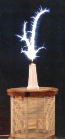
Pancake coils will produce fractals so what is the advantage of trying to build the CIG?
Also why must the coils be the same diameter. It makes calculation complicated and seems impractical.
One final comment about the primary coil. I see no advantage in using flat copper strip as the frequency will be below the 10's megahertz range and as the system will be CW so the primary current will be pretty low.
Cheers!
-speakerbox
I build a spreadsheet to simplify calculations that Eric provided for building a Cosmic Induction Generator (CIG).
I was puzzled but not surprised when his calculations came up way different than JavaTC.
After a bit of messing around I realised they roughly equal the calculated resonant frequency devided by 1 over 2pi.
For example Eric provided the dimensions for a 1mhz coil. JavaTC calculates the resonant frequency to be 1.467mhz.
1.467�(1�2pi) = 0.93392mhz
I also did the same calculation using a 20% and 50% primary height with 62% and 10% spacing. The answers were all about 10% out.
So my question is: what causes these figures to be so different than they should be?
A coiled wire will not have the same resonant frequency as a straight one of the same length.
According to JavaTC and my own experience building coils the coil will work poorly using these plans.
As the primary will oscillate at 1mhz the secondary at 1.4mhz will be 40% detuned.
So is Eric saying his coil is not a air core resonant transformer with frequency matched coils? If not what principle does it operate by?
Pancake coils will produce fractals so what is the advantage of trying to build the CIG?
Also why must the coils be the same diameter. It makes calculation complicated and seems impractical.
One final comment about the primary coil. I see no advantage in using flat copper strip as the frequency will be below the 10's megahertz range and as the system will be CW so the primary current will be pretty low.
Cheers!
-speakerbox
Comment