 Tweet
Tweet
Eric’s Cosmic Ray Detector, deserves its own thread so all the information is located in one place rather than scattered, thus I’ve started a new thread for this topic.
The following are reposts of Eric’s drawings and certain notes.
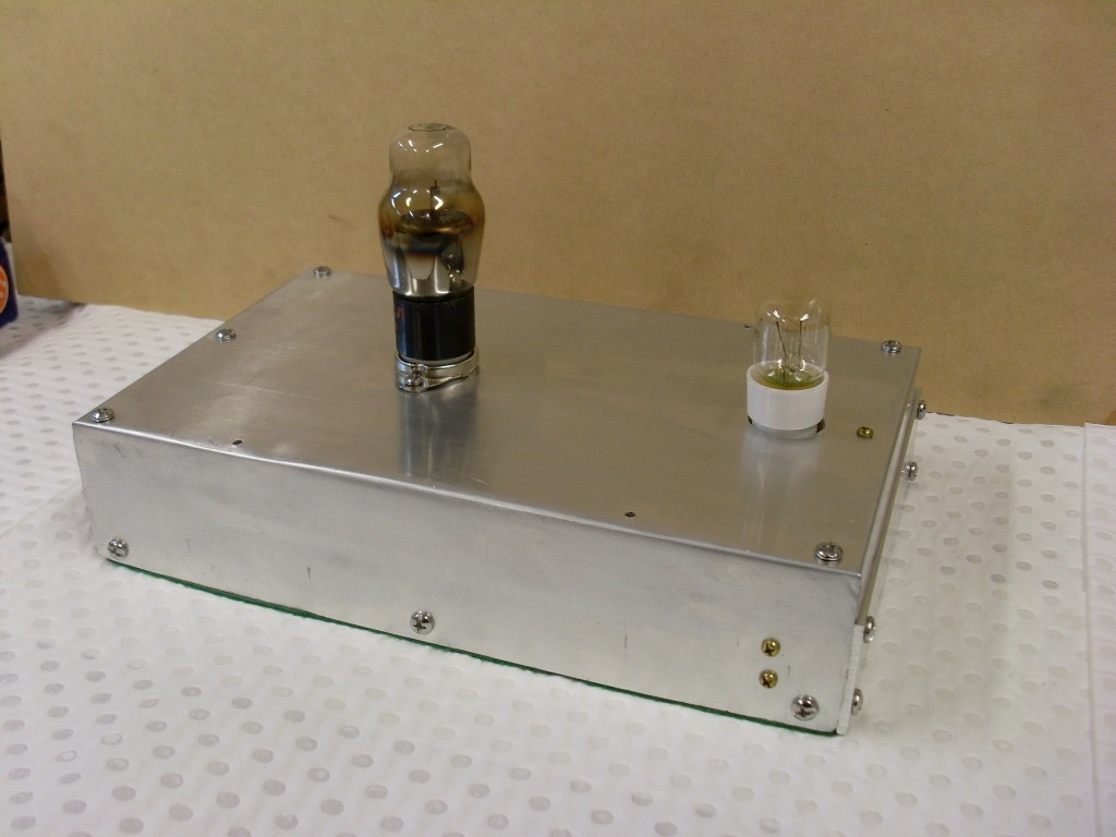
My efforts of construction and testing will follow when ready. Anyone is welcome to post their efforts regarding the Cosmic Ray Detector (CRD) or related information.
Original Circuit:
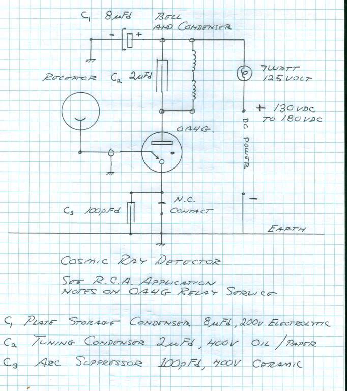
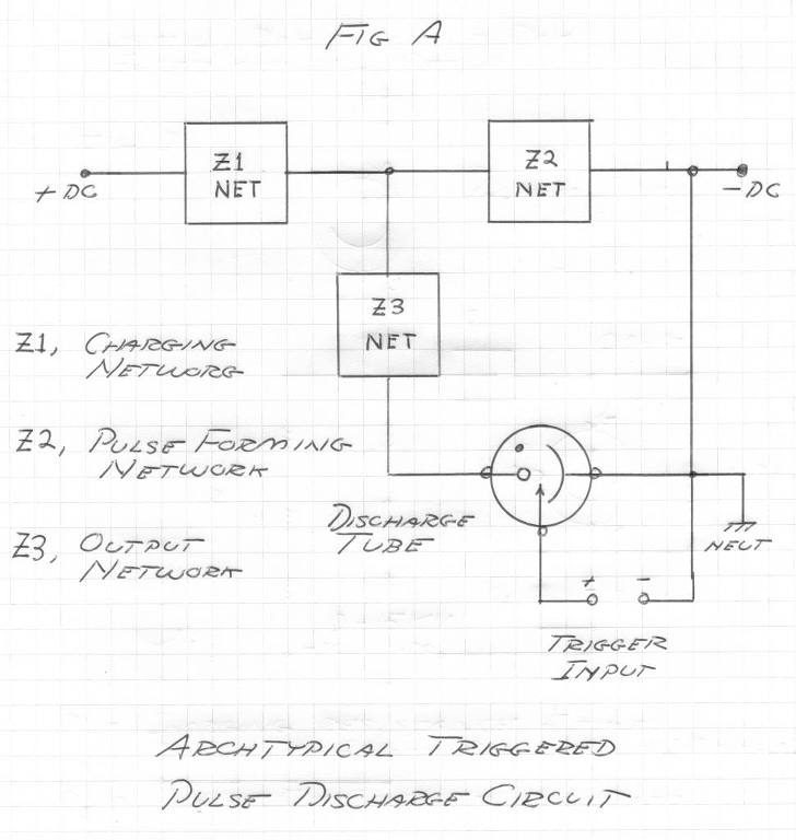
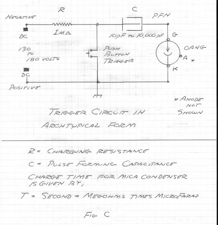
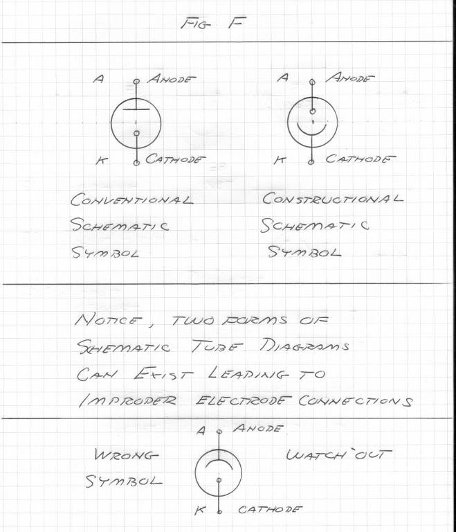
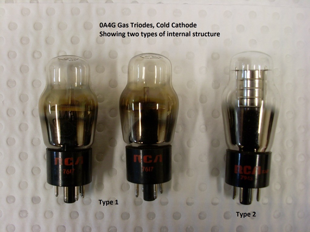
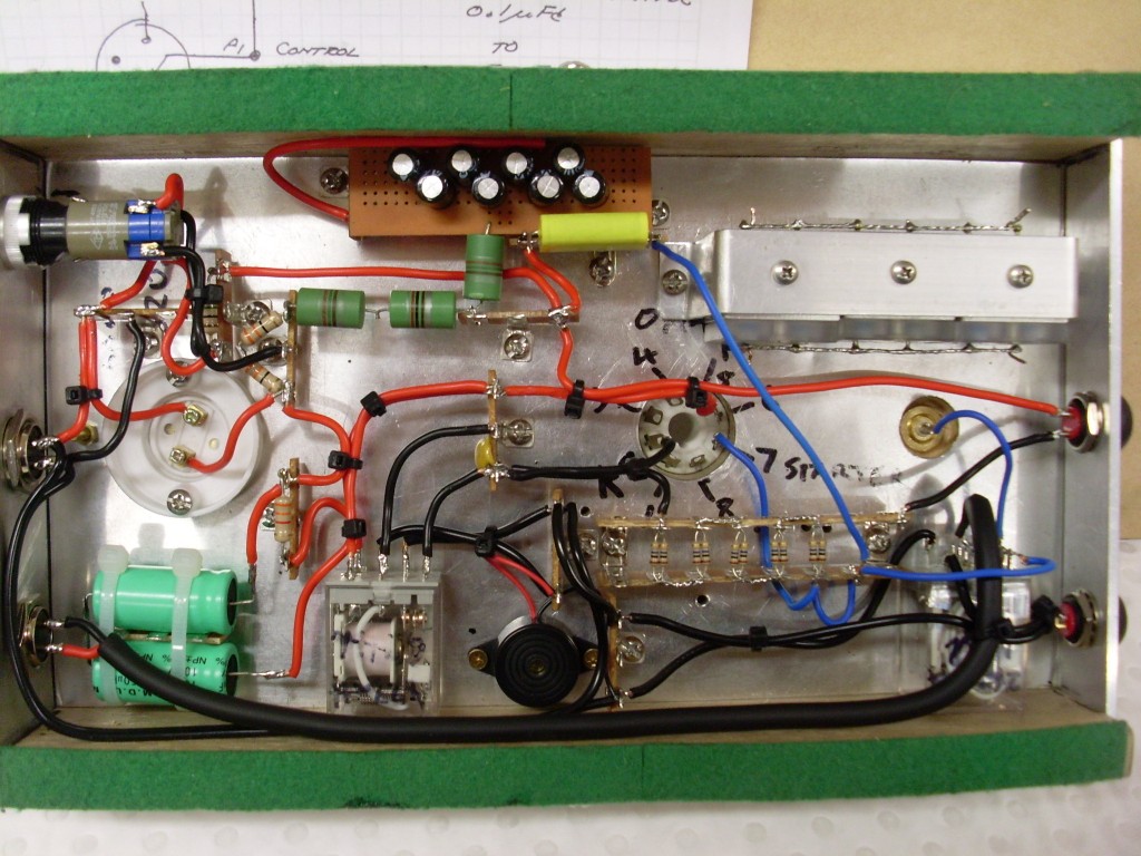
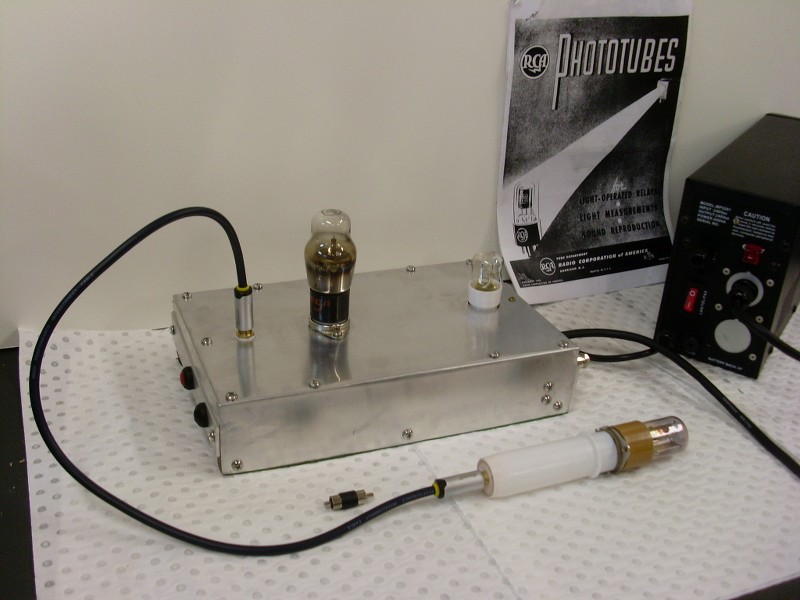
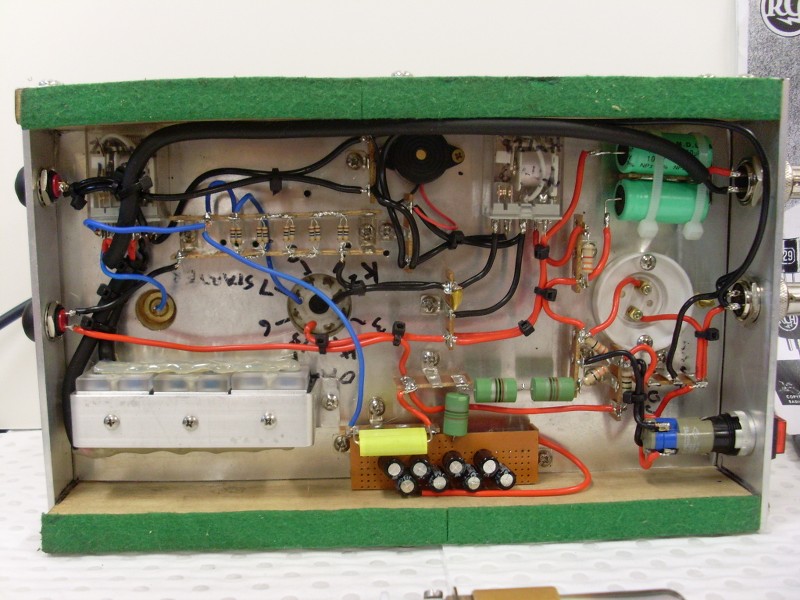
The OA4G has application as a radiant matter detector. The main circuit consists of a Western Electric Telephone Bell in series with the plate supply. The bell condenser should be connected in shunt to the bell windings. A contact should be fitted to the bell armature to break the cathode connection to the OA4G in order to reset the tube. See the Marconi Coherer detector.
(4) The cosmic anode lead connects to the trigger or grid lead of the OA4G. There must be NO DC leakage to ground. For cosmic anodes see Vassilatos "Vril Compendium", and the experiments of Luigi Galvani.
(5) As for detectors into the outer limits the common regenerative detector is the circuit of choice. It is a development of E.H. Armstrong, see "Empire of the Air". The Regenerative Detector is also developed in the Russian parametric paper, an important study. Radionic receivers here are possible, depending on the metallic-dielectric geometry used. Connection with a magnification transformer is possible.
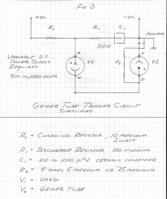
Updated Circuit:

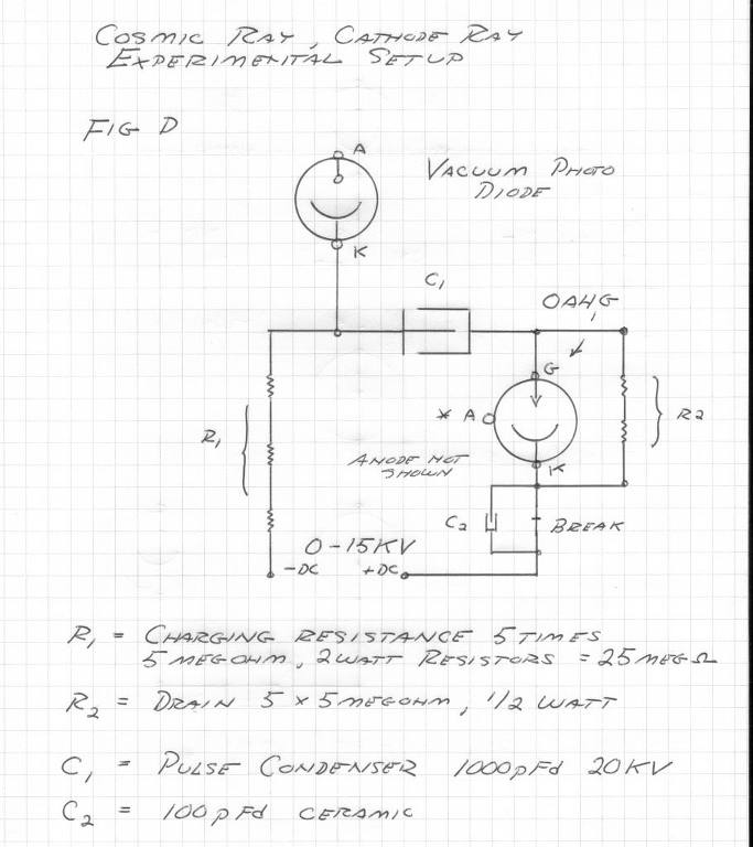
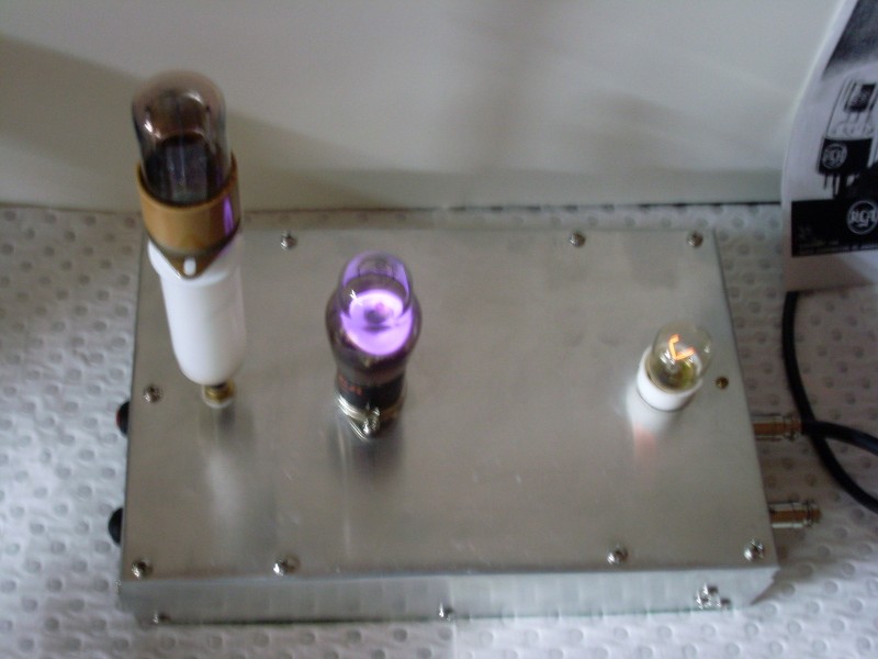
A capacitor has been added to charge the cathode to a negative high potential. This facilitates the tube being able to emit. The capacitor will be in one of two states, either charging (out of the circuit), or running (connected to the cathode)
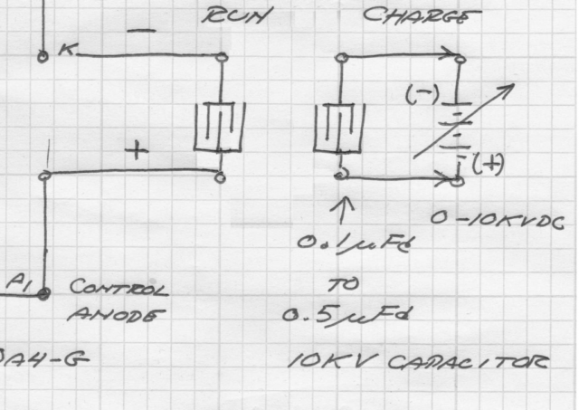
The HV DC charging source must not be in the tube circuit. The smallest possible capacitance that still allows the tube to fire is desirable. A small capacitance won't have enough stored energy at low voltages however, so high voltage DC is required: 0-10 KV.
Different capacitor values at different voltages need to be tried, experimentation is required. Curves need to be drawn showing the minimum voltage at a given capacitance is required.
The following are reposts of Eric’s drawings and certain notes.
My efforts of construction and testing will follow when ready. Anyone is welcome to post their efforts regarding the Cosmic Ray Detector (CRD) or related information.
Original Circuit:
The OA4G has application as a radiant matter detector. The main circuit consists of a Western Electric Telephone Bell in series with the plate supply. The bell condenser should be connected in shunt to the bell windings. A contact should be fitted to the bell armature to break the cathode connection to the OA4G in order to reset the tube. See the Marconi Coherer detector.
(4) The cosmic anode lead connects to the trigger or grid lead of the OA4G. There must be NO DC leakage to ground. For cosmic anodes see Vassilatos "Vril Compendium", and the experiments of Luigi Galvani.
(5) As for detectors into the outer limits the common regenerative detector is the circuit of choice. It is a development of E.H. Armstrong, see "Empire of the Air". The Regenerative Detector is also developed in the Russian parametric paper, an important study. Radionic receivers here are possible, depending on the metallic-dielectric geometry used. Connection with a magnification transformer is possible.
Updated Circuit:
A capacitor has been added to charge the cathode to a negative high potential. This facilitates the tube being able to emit. The capacitor will be in one of two states, either charging (out of the circuit), or running (connected to the cathode)
The HV DC charging source must not be in the tube circuit. The smallest possible capacitance that still allows the tube to fire is desirable. A small capacitance won't have enough stored energy at low voltages however, so high voltage DC is required: 0-10 KV.
Different capacitor values at different voltages need to be tried, experimentation is required. Curves need to be drawn showing the minimum voltage at a given capacitance is required.


Comment