Announcement

Collapse
No announcement yet.

- 5x More Current Out Than In - Validation Of Proof Of Concept -

Collapse
X
 
  • Filter
  • Time
  • Show
Clear All
new posts

  • - 5x More Current Out Than In - Validation Of Proof Of Concept -


    Earth ION Energy

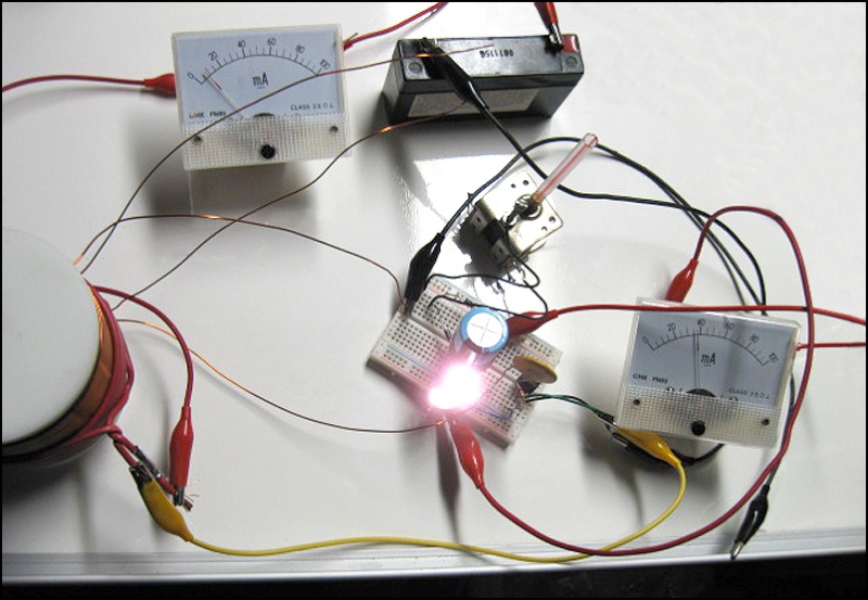
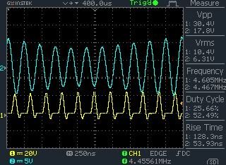
    The photograph above was taken by one of our engineers to validate the technology.

    It was based on Radiant Energy Proof of Concept v2.5

    https://dl.dropbox.com/u/33118048/Ra...eiver-v2.5.pdf


    It contains mostly Bruce A. Perreault's work and some of his own, so it was not built exactly to specification.

    Both ammeters have 10uf caps fitted to them.


    The 2nd Edition Full Version contains the improved v2.6 Proof of Concept Schematic.

    We are currently discussing funding an independent laboratory test.

    We will keep you updated with our progress.

    We hope you can all be part of this project even if that only means you can make a small contribution.

    Please spread the word about EARTH ION ENERGY. For the price of a magazine together we could globally solve our energy needs.

    Last edited by soundiceuk; 09-12-2012, 11:30 PM. Reason: Web Address

  • #2
    Hi soundiceuk,

    I have always enjoyed your posts so please don't take this the wrong way. You are only showing the input and output current. Without the input and output voltage the current doesn't really tell us anything. A simple transformer will increase the current if we wind it for a lower output voltage. What are the input and output voltages? Are they the same as shown in the PDF?

    Respectfully,
    Carroll
    Last edited by citfta; 07-20-2012, 01:37 AM.
    Just because someone disagrees with you does NOT make them your enemy. We can disagree without attacking someone.

    Comment


    • #3
      @soundiceUK

      Thanks for sharing. The photo seems to show a primary and secondary on an air core, yet the schematic shows only L1. Also, the secondary on the photo appears to have four different strands of magnet wire exiting/entering the form. Can you clarify the inductors/transformer? Thanks.
      ----------------------------------------------------
      Alberta is under attack... http://rethinkalberta.com/

      Has anyone seen my Bedini Ceiling Fan that pushes the warm air down, and charges batteries as an added bonus? Me neither. 'Bout time I made one!!!!! :P

      Comment


      • #4
        Hi soundiceuk, so this is part of your patented technology?

        Ash

        Comment


        • #5
          - PRIVATE ENGINEER -

          A quick description of the circuit - the coil is a "mystery coil".

          I'm using the secondary of the coil only and the other coil is left open.

          I wound my own primary on it to form the oscillator, so instead of a separate oscillator driving the tank. It was more consolidated serving the same purpose.

          The output of the secondary coil drives a 3 plate collection system also forming a tank circuit tuned by the air cap.

          The blue cap is 3300uf.

          The input battery is a 6 volt SLA and the output is the 3300uf cap driving 2 - 3.7 volt 30ma 10mm ultrabright LED's in series connected through the mA meter.

          I am "assuming" the input was at least 6 volts and showing 7-10ma on the meter seems pretty obvious that an input of around .06 watts is being used.

          The output I would also "assume" to be in the range of 5-7 volts based on the brightness of the bulbs and the meter is showing slightly over 30 mA.

          Simply a learning tool of my own pursuit and since I didn't have all the components laid out in the schematic I had to be a bit creative and work with what I had on hand.

          The circuit is quite simple as shown by Bruce, I spent maybe an hour putting the circuit together including the time winding the coil but also another 6 or so hours finessing, tinkering, tuning, observing and altering things to get that result. It is not something you can expect to toss together and twist the dial on the air cap and power the world - you have to understand what the circuit is doing. I believe that is all Bruce intended.

          If people simply build it and expect immediate success they will surely be disappointed and fail.

          Also, it is more akin to the 2.6 version than the 2.5 in it's output operation.

          I didn't take any other pictures of it and all the parts are now supporting 2 other test units.

          I tend to move from one build to another fairly quickly as I learn.

          Comment


          • #6
            @ citfta & kcarring

            I hope this answers your questions.

            @ ashtweth

            We need to validate that the technology is valid, safe and reliable.

            Further validation of Bruce's proof of concept circuits will help form the fundamental bedrock to build a globally public owned commercial device.

            We can help make this happen by contributing $5 to SonoMagnetics Trust to support the 2nd Edition research.

            https://www.paypal.com/us/cgi-bin/we...179e3b8dcbd5ee

            Regarding Bruce's patent:

            The patented Ion Valve will never get to market or even begin production because of power and greed.

            There are other alternatives to using the materials in the patent.
            Last edited by soundiceuk; 08-03-2012, 01:01 AM. Reason: Link not working.

            Comment


            • #7
              soundiceuk
              did you use an antenna and a earth ground for it?
              If so, how big is the antenna. I assume, a 555 timer would work as osscilator too?
              Theorizer are like High Voltage. A lot hot Air with no Power behind but they are the dead of applied Work and Ideas.

              Comment


              • #8
                You heard it hear first folks!!!!

                Bronze access has just been upgraded to a FREE 2nd Edition Silver access v0.12 eBook.

                Direct Electrical Power from The Utilization of Earth IONS - 2nd Edition v0.12

                To get a downloadable PDF please contribute $3 to SonoMagnetics Trust via the PayPal link in the above post.


                To see how we have progressed the 1st Edition release on March 22nd 2012

                Here is your FREE 1st Edition.

                https://www.dropbox.com/s/t9n2pjguw5...h%20IONS.pdf?m


                The Gold & Platinum Editions are not ready yet and will feature pictures and videos + independent lab testing.

                This is our chance to own this amazing technology and move forward as one.

                Comment


                • #9
                  It starts to stink.
                  Theorizer are like High Voltage. A lot hot Air with no Power behind but they are the dead of applied Work and Ideas.

                  Comment


                  • #10
                    Nothing but my sweaty socks that stink Joit!

                    It does use a 65' L shaped longwire antenna and an earth ground.

                    The reason why the circuit it is very hard to grasp for 99.9% of people is because there is a gap in our learning about planetary frequencies.

                    The 1st & 2nd Edition were made to try and fill the learning gap and give us a platform to educate and demonstrate the beauty of nature's wheelworks.

                    What these circuits are doing is creating a draft for the ions to flow, like leaving two windows open in your house and also tuning and locking onto a planetery frequency that hardly anyone in the world knows exists.

                    Bruce is not the only one trying to make positive moves with the technology.

                    http://pesn.com/2012/07/09/9602130_K...ies_to_Market/

                    Comment


                    • #11
                      I'll check with - ENGINEERING - about the 555 oscillator for you Joit.

                      Comment


                      • #12
                        @joit a doubt, can we get 4 mhz with a 555 timer? if so can you help with the values? hugs

                        @soundiceuk

                        im also trying this, i was thinking of an LC resonant zero-voltage switching (ZVS) feedding the coil/cap LC but as it is mentioned that "this is acomplished by tunning the L1/C1 combination to slightly lower frequency that the oscilator frequency" im not seeing how can i make it that way, because the ZVS will allways oscilate at the frequency determined by the coil inductance and cap capacitance.

                        i think you should provide clear and clean schematic of oscilator so this can be replicated easily and so validated!

                        thanks

                        Originally posted by Joit View Post
                        soundiceuk
                        did you use an antenna and a earth ground for it?
                        If so, how big is the antenna. I assume, a 555 timer would work as osscilator too?
                        Last edited by TanTric; 07-20-2012, 08:10 PM.
                        Light, I Am!

                        You are Not a Body that has a Spirit, You are a Spirit that Has a Body! There is no Path to Peace, Peace is the Path!

                        Comment


                        • #13
                          @ TanTric

                          https://www.dropbox.com/s/wwnw2i02y7...Hz%20BFO.doc?m

                          Comment


                          • #14
                            @joit

                            Are you absolutely sure you do not want to cash support this copy of amateur radio circuits? I am sure that at least some of it was patented some time in the last century. That does make it revolutionary doesn't it? The only part I don't understand about this project is that if it only costs 10 bucks to make why are we raising money to save the earth? After all the olympics we only get gold and silver but here we can get "bronze"

                            Comment


                            • #15
                              Hopefully we can close the gap in our learning soon and move forward as one with this technology.

                              - PRIVATE ENGINEER -

                              I thought these might be interesting to any one working on the beat frequencies.

                              This first one is when it locked.


                              The yellow is the driven oscillator and the blue is not powered, simply a slave.

                              Below shows the two oscillations when there is no beat lock, both latch on to the same phase.


                              You can tune one oscillator or the other to shift the phases so when one is high the other is low. This is when you start shaking the environment. Below shows the beginning of a phase shift...


                              The next one shows the first one expanded....


                              I find this interesting because when you look at the center of the beat you can see the phase shift but also that the slave oscillator is leading the primary oscillator peaks on ring down, they line up in the center then trail slightly during ring up.

                              I may be interpreting this wrong but in my mind the ring down side is giving energy to the driver and on ring up the driver is giving energy to the slave.

                              Also interesting is both the 1st picture and the last are from the same test oscillator, the difference between the beats is 79000 hz in the first and the second is 138000 hz the first is a harmonic of 7.9 the second 8. With no real way of making tiny precise movements I'd say I came pretty close, this seemed to be the only spot between the pair that I could get a beat lock.

                              Comment

                              Working...
                              X