Announcement

Collapse
No announcement yet.

Bedini-Cole Window Motor Electric motor runs without draining batteries!!!

Collapse
X
 
  • Filter
  • Time
  • Show
Clear All
new posts

  • #46
    Dear DIVERFUN ,

    Sorry to chime in, I think the problem with understanding Fig. 24-3 from your old Electronics Basics book is that the + and - signs shown in it indicate voltage polarities and not current polarities, right? Just consider the coil as a generator with the indicated output voltage polarities as shown in Figure b (when the 8V battery is off).

    If you accept this, then the understanding of the current flow direction will be clear in any coil: when the input current is switched off, field collapses but tries to maintain the original current but due to losses it is not able to (the amplitude of the spike starts decreasing) so the original current starts decreasing in value towards zero (it might change direction after reaching the zero value but this depends on the load across the coil (damping) whether it allows ringing as member citfta referred to).

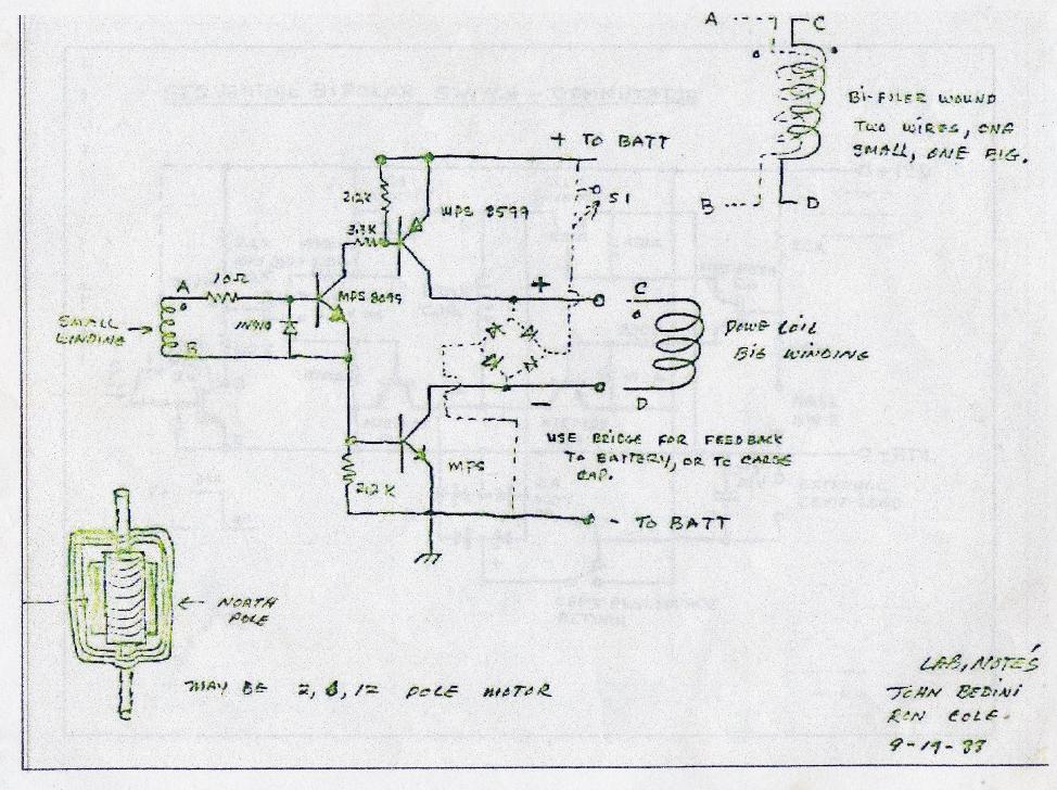
    This also means that in your very first schematic (in your Reply #41) the big coil (L1) still has no discharge path via diodes D2 and D3, UNLESS the winding sense of L3 (the third coil) which is inductively coupled to L1 allowes current flow into capacitor C1 via D4 from the induced spike, okay?

    I notice this because the voltage spike across coil L1 (when Q2 and Q3 are just switched OFF) will have a positive polarity at the collector of Q3 and a negative polarity at the collector of Q2. Your diodes D2 and D3 will block both these voltage polarities as they are drawn, preventing any current flow out of the coil L1. (One more notice: you would have to have a voltage difference first to cause any current flow in a closed circuit.)

    Putting all this otherwise: when you connect a battery across a coil with a given polarity and then you disconnect it, the coil will behave also as a kind of 'battery' (giving out the voltage spike for a short amount of time) but would have an opposite polarity across its terminals with respect to what the battery forced onto it first. When you understand this, all the current flow directions (after the switch-off) will fall in place correctly.

    rgds, Gyula

    Comment


    • #47
      Simple Circuit

      Hi DIVERFUN,

      Let me propose a simple circuit for you to try. I'll try to describe it as I don't have time right now to draw it up. Take a coil and connect a neon bulb in parallel to the coil. An NE2 will work fine. Now connect a diode at the top with the cathode connected to the top of the coil and the anode connected to a 10uf 100 volt cap at the negative terminal of the cap. Now connect a diode at the bottom of the coil with the cathode connected to the positive terminal of the cap and the anode to the bottom of the coil. Now pulse the coil with 12 volts by any method you want whether a relay or by hand just touching the battery leads to the coil. You can even use the Darlington pair transistor circuit.

      You will see the cap charging up. And the neon will not be lighting up. Why? If the current reversed as you have said the diodes should be blocking the current flow to the cap and the neon should be firing because of the higher voltage.

      Now reverse the diodes and the cap and start pulsing the coil again. You will see the cap charging very little and the neon lighting with each discharge of the coil. The cap is only charging because of the ringing of the circuit not from the main discharge as the neon has allowed that to be discharged through it. The diodes are now blocking the initial discharge of the coil.

      Please build this and study the effects and you will see what I mean.

      Recess time!!

      Respectfully, Carroll
      Just because someone disagrees with you does NOT make them your enemy. We can disagree without attacking someone.

      Comment


      • #48
        Hi DIVERFUN,

        I would like to show you this link where the operation of a flyback inductor or transformer is explained. How does a flyback transformer ( or inductor ) work?
        I qoute from the link:

        "Discharge Stage: The current (which creates the magnetic field) from the source is then interrupted by opening a switch, thereby causing the magnetic field to collapse or decrease, hence a reversal in the direction of the magnetic field flux change (negative flux change over time). The negative flux change induces a voltage in the opposite direction from that induced during the charging stage. The terms “flyback” or “kickback” originate from the induced voltage reversal that occurs when the supply current is interrupted. The reversed induced voltage(s) tries to create (induce) a current flow. The open switch prevents current from flowing through the power supply. With the voltage reversed, the diode now permits current flow through it, hence current flows into the capacitor and the load across the capacitor. If current can flow, then the resulting flow of current is in the direction, which tries to maintain the existing magnetic field. The induced current cannot maintain this field but does slow down the decline of the magnetic field. A slower decline translates to a lower induced flyback voltage. If current cannot flow, the magnetic field will decline very rapidly and consequently create a much higher induced voltage. In effect, the flyback action will create the necessary voltage needed to discharge the energy stored in the flyback transformer or inductor."

        I hope this also helps.

        rgds, Gyula

        PS On general working of such transformers: Flyback Transformers - Custom Built transformers with schematics including flyback circuit topology, inductor transformer
        Last edited by gyula; 07-25-2013, 01:32 PM. Reason: addition of a link

        Comment


        • #49
          May Have found it

          Ok, sometimes you must walk away from things for a long time and just let things fester in your head. If you look at the circuit diagram Mike posted you will see something that I may have overlooked. I don’t know why I missed it, could have been thinking about something else. When I hooked a small battery in place of mikes ss circuit the motor ran as normal. That is why I came to the conclusion that mike hid a battery in the ss relay. So now back to the circuit, if you look you will see that when the switch is on the two coils make up an Autoformer, this type of device builds voltage without changing the impedance of the driving coil so the driving coil does not see the load of the capacitor the Autoformer works like a basic car spark coil. The only reason I say this is I had a job with some radio circuits
          where I had to make this type of transformer to supply the load of the antenna without effecting the transmitter. Amplifiers in the 70’s used these transformers (Mcintosh) you could short the amp out and nothing would happen. I have experimented with this type of transformer and it is possible to build a Window Motor to run like this but you cannot take any power from it, Unity. I know this is late timing but at least I have posted it.
          John B
          John Bedini
          www.johnbedini.net

          Comment


          • #50
            Thankyou for the update, any information is good information, even when late

            Comment


            • #51
              Originally posted by John_Bedini View Post
              I have experimented with this type of transformer and it is possible to build a Window Motor to run like this but you cannot take any power from it, Unity. I know this is late timing but at least I have posted it.
              John B

              Hi John

              Good to see you back diggin in the posts. Unity is good for me.

              I am learning. I use to think UNITY? So what, but now I see that

              UNITY shows that all of the models in science are lacking because

              the system teaches under unity. Maybe somebody could throw

              a set of Howards gates on one and go overUNITY

              I see your part 22 16 pole Ferris wheel, she really takes the cake.

              Michael Rowland (Central Kansas USA)

              Comment


              • #52
                May Have found it

                Yes, Unity is good, I just don’t know how I could have missed this, it’s really bugging me. I have done a test with the original motor and if you hook a bridge and a capacitor to the window coil and spin the motor up it charges the cap fast. Now if you pulse the motor with S1 it keeps running for a very long time. The key to it is the transformer as I stated. I could not find a diagram
                To post what I mean so I must draw it. It is important on how the second part of the coil is hooked up. The polarity must be correct and the timing of the switch. Be back later with drawing
                John B
                John Bedini
                www.johnbedini.net

                Comment


                • #53
                  Originally posted by John_Bedini View Post
                  Yes, Unity is good, I just don’t know how I could have missed this, it’s really bugging me. I have done a test with the original motor and if you hook a bridge and a capacitor to the window coil and spin the motor up it charges the cap fast. Now if you pulse the motor with S1 it keeps running for a very long time. The key to it is the transformer as I stated. I could not find a diagram
                  To post what I mean so I must draw it. It is important on how the second part of the coil is hooked up. The polarity must be correct and the timing of the switch. Be back later with drawing
                  John B
                  Good man John I knew I could count on you.

                  I would rather have a souped up window motor than

                  those other imitations. Maybe if we keep it going those guys

                  will see this post and find out what you have to say.

                  You know I look at this simple circuit and really it is

                  not a hard one to build. And yes I heard you the first time

                  on the transformers and how your job way back took you

                  in that direction. I will have to play catch up and love

                  every minute of it. I just don't know much about it yet.

                  To me UNITY means a step up from this University dogma.

                  Then it proves that we can go beyond that. I hear ya on the

                  way you feel about thinking he had a battery in there.

                  So many try to pull the wool over my head I understand.


                  We will be looking forward to your help John.
                  Last edited by BroMikey; 07-21-2015, 07:36 AM.

                  Comment


                  • #54
                    JB welcome back.
                    Hope everyone had a great time this year at Coeur d' Alene.
                    The project with unity might really be a doable interesting hands on project.

                    "The Motor that runs without draining the batteries"

                    https://www.youtube.com/watch?v=r1xZJYKpVf4

                    https://www.youtube.com/watch?featur...pPLQBls#t=1108

                    Great progress on the solar system solar tracker, Rcharger, nickel hydrate cells,
                    Alum conversion has been great advancement for off grid systems, Nice work and to
                    John, Chuck and everyone at Energenx, great job this year !
                    Last edited by mikrovolt; 07-22-2015, 10:26 AM.

                    Comment


                    • #55
                      John never left here he is with his window motor. And

                      I heard Yaro say John showed it at the ENERGY POW WOW!!

                      https://www.youtube.com/watch?v=F3QHsoyGH5I

                      I saw someone use hall effects and MOT coils to make quick

                      work of the window motor.


                      Take your time John, I know you are probably wiped out from

                      all the traffic up there in Idaho. As crude as I often sound I

                      really do enjoy your down to earth performances.

                      Comment


                      • #56
                        Self Running Window Motor

                        Duplicated here: Building a window motor
                        Sincerely,
                        Aaron Murakami

                        Books & Videos https://emediapress.com
                        Conference http://energyscienceconference.com
                        RPX & MWO http://vril.io

                        Comment


                        • #57
                          Originally posted by Aaron View Post
                          Duplicated here: Building a window motor

                          Thanks Aaron

                          for the heads up. I went over there and looked at the posts

                          and I could not find a window motor video by anyone of the

                          replicators. Maybe I missed it? Also unless you sign in as a member

                          that information in picture form is confidential.

                          I am glad for the text.

                          I will go back and look to see if I can open a picture or find

                          a video presentation showing how their particular replication

                          of the JOHN BEDINI WINDOW MOTOR working, because that is

                          what it takes.

                          BRB


                          Okay I found a DADHAV video from 2010?
                          Last edited by BroMikey; 07-28-2015, 03:00 AM.

                          Comment


                          • #58
                            There is no better information than what John Bedini has.

                            https://www.youtube.com/watch?v=F3QHsoyGH5I

                            When John approves the next video for a replication he

                            deems comparable, then I will take note.

                            John bedini has said many times when he pulled out of forums

                            and groups that the stuff on the internet is not what he is doing.

                            Or in other words, if I don't hear it from John Bedini then I

                            think it is not completely a certified replicator.


                            Unless I get it right from the horses mouth I won't know.


                            It looks like I need to get my lathe warmed up cause John

                            is in full swing again. As usual new things on the horizon.

                            I am getting excited about this new design.


                            And also a special thx to Aaron and all of the people

                            who work with John to make these learning experiences

                            possible.

                            You guys are awesome folks, well worth the money.

                            Comment


                            • #59
                              Window Motor TidBits

                              Hello Jeff
                              There's been many different kinds of window motors built through the years. There have been some pretty good threads about them as well. I'm sorry to say I don't remember where they where to help you out with that. You will have some digging to do. I'll share a few of my experiences with you if it will help. There are pictures of a jig for winding coils. A rectangle coil is not the only coil to wind for a motor. If you are using three coils it is beneficial to use a wooden jig like is pictured in some of JB's literature. Again, I don't have instant reference to it but is is there. The issue of using an iron core or rotor is a mater of preference. I have used both iron and Delrin. I personally prefer a mild steel rotor. I do not use a hex shape and prefer to mill slots for the magnets. I'm not sure what you mean by a compound configuration but you should use six magnets with alternating poles outward on the faces. This is the best way to start but experimenting with what is known as a notch rotor also has some interesting results. Your windings can vary dramatically depending on what you are trying to accomplish. Higher turns ratios say in the 400 turns or more will give you a slower but stronger motor that is easy to trigger and has low current draw. Less turns say in the 200-300 turns area will give higher RPM's with less torque but higher current draw. The WM can run from an SSG, half wave, full wave or Single Coil Motor Circuit. In all cases you are not likely to have charging results that would be better than a monopole motor. I would suggest winding two triggers and one power coil or better yet add an additional power coil to experiment with a generator circuit. If you haven't been there yet, you are welcome to visit my channel where I have some videos of a small and very efficient motors. The first one shows how I constructed mine. Here are a few links:
                              Window Motor Assembly And Capacitor Test - YouTube
                              Window Motor Running On Capacitors - YouTube
                              Window Motor On Water Battery & Solar + (Notch Rotor) - YouTube
                              There is other videos that pertain to the window motors there as well. I hope something here might be of some use to you since you are just starting to learn about these fun motors. I will be posting some other videos soon with a different style motors running from a circuit that doesn't require a standard trigger source so you may want to check back later as well.
                              Take care.
                              John Hav

                              So the first stage would be the SSG circuit (probably in GEN MODE), then the output of the ssg circuit would go to the cap that will power the bedini-cole circuit (that will give a really strong extra punch to the rotor if the cap is high in voltage and capacity), then I can use the output of the bedini-cole again, maybe to feed the bedini-cole cap or a second cap powering another bedini-cole.

                              I know that the output of the SSG and the bedini cole is always less than what I put in, but let's say that with the ssg I get 3000 rpm, then with the output of the ssg into the bedini-cole I could get another 1500 rpm, and then another 750 rpm more, etc, etc. in 3 stages I could get 5000++ RPM using the same power.

                              Then I am going to have regular generator coils to charge a 2nd battery. GEN COILS -> COMPARATOR CAP DUMP -> 2nd BATTERY.

                              And I can probably also include some tesla nodes all over the place.

                              I made a bedini-cole circuit the other day, and used the one in the image called 1GT, like the ferris wheel but with just power coil (ferris wheel used 3 parallel coils),

                              basicly instead of the trigger winding it uses a hall sensor.

                              that one is: 404 (Page Not Found) Error - Ever feel like you're in the wrong place?

                              if you google "bedini-cole circuit" you will get a looooot of variants of the same circuit,

                              I have an issue with the idea about running a ssg circuit, and send the recovery to a cap that would be the source for a bedini-cole circuit in the same rotor.

                              The SSG circuit in radiant mode tuned to 1 pulse per magnet would give me a RPM of aprox 3200. but with the secondary circuit in place (bedini-cole) the RPM went down to 2000+ , so I started to try things to see what was causing the RPM loss... After some tests, it seems that the bedini-cole circuit is causing drag even if it is not triggered, is that normal???

                              I connected the SSG circuit to run the rotor and the output of the ssg was sent to a comparator. Then I placed again the bedini-cole circuit with an empty cap as power source and the drag started again, there is power been sent to the primary of the bedini-cole when the rotor is spinning, by normal induction (the output of the bedini-cole was not connected to anything) I don't know why this is happening since the power coil is isolated from the power source (empty cap) by the 2 transistors. Could this be happening because of the reverse breakdown of the transistors???

                              Any advice?


                              best,

                              Alvaro
                              Originally posted by Gary

                              Here you go.

                              http://www.icehouse.net/john1/dsw1.jpg

                              This is found under "Motor diagrams and lab Notes" on John's old "icehouse" web site JOHN BEDINI'S COLLECTION OF FREE ENERGY MACHINES

                              Sequential Bipolar Switch - Commutator.jpg

                              SequentialBipolarCircuit.jpg


                              Last edited by BroMikey; 07-28-2015, 05:37 AM.

                              Comment


                              • #60
                                Collection of facts.


                                Originally posted by Aaron
                                Analysis by John Bedini PART 1

                                Analysis by John Bedini PART 1

                                I'm posting some deductive reasoning by John Bedini that he posted
                                online. These are the keys to making it work properly and his comments
                                are an analysis on what Mike said about his modification of John's circuit.

                                ----------------

                                Everbody read Mike's story it will help.

                                Everone just read mikes story
                                John


                                Hi Dom,

                                wind your coil yet?, look for about 6-8 ohms on the main winding this gives a large back EMF wich charges the cap quick at first.
                                I will try to attach the video of my window type motor now follow the first cct and yes trigger is smaller wire. The hall effect transistor is to activate sw1 I use a solid state relay for sw1 wind as much turns as possible try to get above 6 ohm. The circuit will need a battery for power source.. Their are some modifications needed for acheiving unity, then you can get rid of the battery. Dont worry about that for now just get it to run with a battery.Also I made a mistake the main winding on my motor is 46 ohms
                                so 40-60 ohms sorry about that .No in the video the motor was powered by capicitance only. no battery. Trifiler wound I must warn you though if you are thinking this is some sort of overunity it is not. If you add a load the motor will slowly come to a stop.

                                Yes feedback, and play with sw1 timing I must tell you I use the third winding on my stator coil as a generator winding to charge the cap up from 0v, then when the transistors begin to pulse the back emf through sw1 brings the voltage on the cap even higher till it levels and the motor is then runing at unity (this is just what I think is hapening and I could be missing somthing here)


                                I don't Know how long the motor can run for, but I always stop it after a few hours or so. I am scared to leave it running unattended (a fire or explosion would not be good)the running voltage is higher when I give it a big spin by hand. so far every time I ran it the voltage has always leveled off some where bellow 12v or so my cap is good up to 25v
                                glad to here that you have started construction allright after tracing all the wires I have come up with a diagram of the modification. and a close call, I had found the motor would not run after a couple wires were swiched around by accident. coil polarity is very important. yes same as Bedini/Cole.All components are the same except for the added parts a hall IC and a ss relay and also third winding.

                                Main winding is connected at the collectors. follow Bedini/Cole cct great work.
                                you must get your window motor running,then we can talk about charge timing and unity.study the scope shots I posted and you will get an idea of timing. Two EMF spikes per cycle
                                I go back to work one more thing before I go, When you go to run your motor have a AM radio close to the stator coil you should here two cracks brodcasted for every magnet pair passing. a quick way to tell if you are hooked up correctly. This link is very good Schematics Illustrated must check it out

                                I learned alot from these illustrations, look at the commutator to see the timing , the bad news, I left my window motor running last night. Now it does not run at all. I will check all components after work.I feel very disapointed. OK back from work now I check the motor. I did a quick visual inspection and it looks OK and the cap holds a charge but when I turn the shaft it does not run, more checks.


                                I think the third winding is allways charging the cap the ss relay puts the main winding in series with the third winding at the correct time, take into account the rectifier diode in between them.
                                ps: looks like the hall ic is not working and also the PNP, the ss relay is fine, I have no more hall ic's and only a few PNP's.This suxs .

                                anyway I figured I would take some pictures of the stator and post soon This is not overunity, just a motor that can charge a cap and run off it for a wile.
                                Scope shots were taken dirrectly off the coil. I will post more detail when I have my motor running again.I will scavenge up a hall ic from something.

                                I don't know if all is needed for the circuit.I just know that this is how I got it to run longer. how long I dont know so far maby a couple hours. I belive it is working at or near unity. i will swap the bad parts now and try to get it running again. As for the posistion of my flywheel magnets I will give that info later after I have finished my testing.
                                Oh and the scope shots, the third winding shot scope is set to diffrent scope timing. yes the original circuit will charge the cap my modification charged the cap from 0v faster
                                yes somthing is wrong with the cap. If I charge it with 12v it will not hold long and spark from discharge is week.Still looking for a hall ic any ideas where to find one 3030 also did anyone find this paticular cap I have only one and the place where I got it, BG Micro no longer has any.

                                maby another big cap will take its place. can run the motor now but only with battery power. back to where I started.

                                I will get a hall sw at the local IC Supply store in the morning. any body have a running motor yet I know Dom looked realy close to finished.


                                OK Stefan, on second look your circuit is correct. the ss relay on your circuit looked wrong but I see it now

                                I know that the third winding charges the cap. and I think somthing coming through the ss relay helps this charge.
                                still trying to get my motor to work correctly, It has prooven to be harder than I thought.
                                I will post new scope shots soon

                                I just want to say that I have never claimed this to be overunity I think it is near unity the third winding charges the cap quickly and the motor runs of this charge for a long time not forever.
                                It makes me happy to see another window motor running.now what I did after getting my motor to run without any mods.
                                I would use it to charge a second battery hopeing I could switch the batteries over and over and it would run for ever, this was not the case, then I found out that if I charged a large cap up with it the motor drew less current from the battery. this was with sw1 between cap+ and bat+,,monitor your input current with diffrent caps to see what works best. I get 2.8v ac spinning by hand try it with just the main coil to the bridge to the cap and see how fast you can charge the cap to 6v by hand and let me know your results
                                4.5v ac main winding
                                2.2v ac trigger winding
                                2.8 v ac third winding
                                stefan please show me were to place scope leeds on the diagram I posted Stefan please slow down the questions here are the scope shots you wanted

                                Main is top trace on both 1st shot is the main and trigger windings 2nd shot is the main and third windings I will do more tomorrow I am waiting for a hall ic so please be patient

                                OK guys I got the hall ic and the motor is working again here are the scope shots taken across cap neg. and ss relay output before diode.

                                scope set at 2v per div. at 10 ms per div. first shot is with hall sensor hooked up and the second is without it hooked up
                                I have posted my full circuit diagram allready. but here it is again. i found this to work best for my setup.

                                please follow it exactly making no changes so we can compare results taken across cap neg. and ss relay output before diode.
                                scope neg to cap neg no it will not run long without hall sensing. I pulled the hall output to ss relay, I spun it by hand for the scope shot (without hall ss relay)
                                Lets build and then compare results I am going to build another to the same specs and see if it performes the same.

                                When you get your motor to run on a battery, charge a cap off the bridge dc then time the ss relay to dump this charge back on the battery. when you get the correct timing the motor will draw little to no current from the battery. this will be the same timing for the moddified circuit. use three magnets in triangle formation.
                                Hope this helps

                                cheers mike


                                Aaron Murakami

                                Comment

                                Working...
                                X