Announcement

Collapse
No announcement yet.

Eric's "Crystal Radio Initiative" Challenge

Collapse
X
 
  • Filter
  • Time
  • Show
Clear All
new posts

  • dR-Green
    replied
    Well, there's no polite way to say this so I'll just cut to the chase - Konstantin Meyl is absolutely wrong. A transmitter and receiver is not two halves.

    Tesla gives one description, Meyl gives another. It works like Tesla says it works, no more pondering necessary. That is absolutely obvious to anyone who uses it, there's no possibility of coming to false conclusions unless one is literally blind to the truth of what's right in front of their eyes. Throw the Meyl books in the trash where they belong, he's only causing people to be confused.

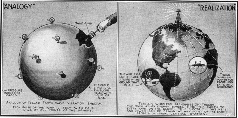
    How does Tesla's hand pump analogy to describe the operation of his own system fit with the false information that Meyl is spreading?


    The information is modulated power.

    Originally posted by Kokomoj0 View Post
    Teslas transmitter was not intended or designed to 'radiate' an infinitely 'expanding' wave front where the output disperses decreasing by the square of the distance, it was designed to resonate between the 2 halves which allows for nearly complete power transfer between them with very minor losses.
    It's designed for 1/4 wave resonance, period. The transmitter is the 1/4 wave resonator. A receiver is a separate 1/4 wave resonator. Did everyone forget that Tesla's Colorado Springs experiments consisted of a 1/4 wave TRANSMITTER? Where was the receiver to make up the other half of the circuit? Where was the other half of Wardenclyffe? You don't need a receiver to make the transmitter transmit, it works independently. You don't even need a resonant receiver to receive said energy near the earth terminal of the transmitter, you can plug your diodes directly into the earth and the earphone works.

    The amount of power received is not a matter of the amount of space or air or distance between the transmitter and the load. For those who don't listen to Meyl, it's no surprise at all that what determines the amount of power received is ONLY the distance between the GROUND TERMINAL of the transmitter and the load. The load doesn't care how far away the transmitter is in space, it only cares about the ground terminal.

    It's not one half of a complete circuit. It already IS a complete circuit. It's a single wire transmission system. The transmitter and receiver are merely transformers. What is the purpose of transformers in the existing power distribution network? ...

    Originally posted by Nikola Tesla
    This mode of conveying electrical energy to a distance is not 'wireless' in the popular sense, but a transmission through a conductor, and one which is incomparably more perfect than any artificial one. All impediments of conduction arise from confinement of the electric and magnetic fluxes to narrow channels. The globe is free of such cramping and hinderment. It is an ideal conductor because of its immensity, isolation in space, and geometrical form. Its singleness is only an apparent limitation, for by impressing upon it numerous non-interfering vibrations, the flow of energy may be directed through any number of paths which, though bodily connected, are yet perfectly distinct and separate like ever so many cables. Any apparatus, then, which can be operated through one or more wires, at distances obviously limited, can likewise be worked without artificial conductors, and with the same facility and precision, at distances without limit other than that imposed by the physical dimensions of the globe.
    Last edited by dR-Green; 04-05-2018, 12:52 PM.

    Leave a comment:


  • Kokomoj0
    replied
    Originally posted by dR-Green View Post
    It seems perfectly feasible to me, but the earthing is as important as the coil. I've received a signal using a flat spiral coil, and what's more, the signal of the normal radio receiver gets stronger when the coil is being used. It becomes a passive repeater. The radio station is already powering your earphone, so what limits the amount of energy that you're receiving? I built the simple SEC circuit once but I've never had much interest in that sort of thing. Where do they connect the output of the secondary? ...
    Its not the same as a tesla T/R. The signal from your radio station is the result of resonating a 'stick', not in the same 'sense' as teslas coils so there is no way to lock into it so to speak like you can with a tc because a standard bc station operates fully decoupled from the receiver.

    The reason the TC can have a remote receiver and actually receive 'power' is because with tesla the coils are effectively splitting a coupled resonant tank circuit in half then moving them apart using the earth as a connecting wire between the 2 and a capacitive coupling through the air.

    From Prof. Dr.-Ing. Konstantin Meyl


    Tesla's the receiver completes or is the second half of a single resonant tank circuit which is why you get high power from it at a distance. Everything gets transferred since it operates as a single coil that is simply separated or split in 1/2.

    In the the case of the resonant stick, it completes or is its own circuit, (so to speak), so you cant build another radio tower in the far field that is an exact replica of the first and transmit 'power' to it, because the design is not a coupled design, however you can use it to transmit a signal that that decreases like any other other transverse wave at the square of the distance and a coil that can resonates at the same freq can pick up and receive very low energy signals, enough to power your headset.

    Lighting an incandescent bulb in far field using a signal from a stick in the air cant happen where as in teslas split coil design it can.

    Stifflers 3 coil SEC circuit is fascinating and his design methods should be used for more efficient tc's imo since we are trying to tune to the environment around us.

    The circuit appears to take existing rf noise and tuning what he calls a spatially a resonant tank to it. I hazard to say it may have possibilities if you can tune that to a nearby radio station with build a big enough tank. Now you use the self resonant tank to trigger off the radio signal, which may, that is 'may' possibly be capable of building big enough to actually light an incandescent bulb in some fashion. I get this vision of a 60 cycle spatially resonant tank, 50 for you LOL

    The cool thing is that it demonstrates how particular and precise one must be to actually get these high z devices to work, not the typical cobble jobs with completely faulty measuring techniques we usually see out here. Its not in making perfect calculations either, that only gets a person close because every environment has too many undetermined variables, its like tesla pointed out, its an art which to me means the fine tuning is done by feel, and of course now days with a scope and spectrum analyser etc..


    3-Coil srf Demo Part#1 - YouTube

    3-Coil srf Demo Part#2 - YouTube

    3-Coil srf Demo Part#3 - YouTube

    http://www.youtube.com/watch?v=l9q_r5_jEP4

    https://www.youtube.com/watch?v=PAezDm2jvbA

    https://www.youtube.com/watch?v=knLfvO_GGaQ

    https://www.youtube.com/watch?v=r1Abr8AnuZQ

    https://www.youtube.com/watch?time_c...&v=LD8OkbumcY0

    more in depth explanation to the difference in the transmission.
    https://www.youtube.com/watch?v=F7SR4vF_pug&t=11s

    So to illustrate the point I am trying to make more clearly I took some time to dig up a couple schematics as to why you cannot light a bulb in far field with a standard broadcast transmitter:


    Teslas transmiter receiver operates like this:


    Spigel has a nice picture that I cropped to show that tesla transmitter is based upon
    a tank circuit that stretches out over miles by an interconnecting wire with full circulating
    power resonating between the 2 halves:


    http://www.spigellab.com/2016/05/27/...nd-connection/

    and of course he has a nice video:

    Basic Tesla's Experiments (Part 1) - 100W Wireless Transmission without Ground Connection
    https://www.youtube.com/watch?v=CbqR8EpIP04

    Now lets look at a broadcast antenna circuit:


    http://electronics-diy.com/1-watt-fm...-amplifier.php


    all you have is a tiny load matching circuit so you dont cook your transistor or tube, which works like this:

    The rod for a monopole or in this case a dipole is the resonator now you can flip that to vertical to get:


    The principal of operation of a standard broadcast transmitter is completely different. Teslas transmitter was not intended or designed to 'radiate' an infinitely 'expanding' wave front where the output disperses decreasing by the square of the distance, it was designed to resonate between the 2 halves which allows for nearly complete power transfer between them with very minor losses.


    You can calculate the 'maximum' current of a standard broadcast rig based on the field strength, distance, length-area of the metal of your receiving rod antenna or coil that can be actually be struck by the passing waves.

    Originally posted by dR-Green View Post
    so what limits the amount of energy that you're receiving?
    For a tesla being an air coil the internal resistance of wire caps etc.

    For a broadcast antenna its the maximum tube/transistor output that translates into actual radiated power.

    For ideal transmitter rig+antenna etc, everything set up perfect with perfect conditions;

    10Mhz
    For actual radiated wattage of 100,000w using a dipole, typical efficiencies can be seen up to 70% max unless they are doing something new I am not aware of, roughly input power of 130,000 watts.

    For 130,000 watts input, thats 220vac and 590amp service requirements.
    For 2000meters (Approx 1 mile)
    .00329 Watts/m^2 (with dipole 2.19gain)
    1.11V/m
    .00296A/m

    They have a handy calculator here:
    http://www.compeng.com.au/rf-calculator/

    No energy is reflected back to be circulated in a resonant tank with the standard broadcasting transmitter rig like there is with a pair of TMT/Rs, the radiated waves from SB simply keep right on going to infinity.


    If Tesla is correct and I fully expect he is, the only losses you would see from the TMT's would be primarily from the ground resistance, say if you have 1000 ohms over a distance of the same mile, since the earth in an ideal situation would be a dead zero ohm short between the 2 two towers.

    Radiation dispersion
    In standard broadcast the waves pass and keep going, how much power you get is dependent on how big your antenna is, whereas with tesla its dependent on the amount of power your tank is capable of building up between them. Teslas system is captive, broadcast is not. For teslas the energy does not escape, it is received and sent (reflected) right back to the transmitter as a result of resonance contrary to the standard broadcast rig which continues to infinity.


    In broadcast the transistor (or spark doesnt matter) directly drives a resonant rod that is cut to 1/4 wavelength, its for all intents and purposes a power driven tankless output which is decoupled from the receiver, hence will not transmit 'power', only information. I was severely ridiculed, ostracized and branded as an ignorant heretic who had the audacity to defy god because I didnt buy the wooden nickels or waste my time in an exercise of futility with this frivolous challenge which is why no one has seen much of me around here or any other overunity forum for the last several years. I assure you that no one has or will ever light a several watt incandescent bulb in the 'far field' (like you can with the tesla desgn) from a standard broadcast tower with a standard receiving tuning coil or tesla type coil arrangement tuned to its broadcast frequency unless they are transmitting 5 billion terrajiggawatts in which case you would not be able to place your receiving antenna near it without being nuked. https://www.youtube.com/watch?v=I5cYgRnfFDA The only thing the 2 designs have in common is they are both 1/4 wavelength. Now if we jump back to stifflers work, he is taking a -70dbm (presumably a signal) and magnifying it to light I think he got as high as 28 leds with it, definitely 1, with no power source connected, and its been replicated.

    Begs the question, and I will leave you with this thought.....what if we had a wardencliffe driven by an equally sized stiffler circuit

    Unfortunately its the main objective of governments and profiteers et al, to insure and enforce commercial intercourse. (at 'any' cost) and one way to accomplish that is lead people down a path of failure so they dismiss the whole concept, and I am almost too old to care. Probably not the response you expected.
    Last edited by Kokomoj0; 04-06-2018, 01:14 AM.

    Leave a comment:


  • dR-Green
    replied
    Originally posted by Kokomoj0 View Post
    Well the presumption was that someone could build a cyrstal radio and light a several watt bulb by tuning into a nearby radio station and frankly I cant see that happening which is why I never built it aside from the fact that I built them when I was a kid so its not much fun for me 60 years after the fact. ever do any stiffler replications?
    It seems perfectly feasible to me, but the earthing is as important as the coil. I've received a signal using a flat spiral coil, and what's more, the signal of the normal radio receiver gets stronger when the coil is being used. It becomes a passive repeater. The radio station is already powering your earphone, so what limits the amount of energy that you're receiving? I built the simple SEC circuit once but I've never had much interest in that sort of thing. Where do they connect the output of the secondary? ...

    Leave a comment:


  • Kokomoj0
    replied
    Originally posted by dR-Green View Post
    I don't get any reports back, but some sort of experimenter space/forum where people can post about their builds and experience on the web site is on the cards.

    P.S. the discount is now 20% and now includes Bitcoin Cash and Ripple. Litecoin probably coming soon.
    Well the presumption was that someone could build a cyrstal radio and light a several watt bulb by tuning into a nearby radio station and frankly I cant see that happening which is why I never built it aside from the fact that I built them when I was a kid so its not much fun for me 60 years after the fact. ever do any stiffler replications?

    Leave a comment:


  • dR-Green
    replied
    Originally posted by Kokomoj0 View Post
    How did everyone make out on Erics challenge to use this to tune into an am radio station to light a light bulb?
    I don't get any reports back, but some sort of experimenter space/forum where people can post about their builds and experience on the web site is on the cards.

    P.S. the discount is now 20% and now includes Bitcoin Cash and Ripple. Litecoin probably coming soon.

    Leave a comment:


  • Kokomoj0
    replied
    Originally posted by dR-Green View Post
    Until further notice, you'll get 10% off your basket total when you pay with Bitcoin or Ether.

    The Crystal Radio Initiative Calculator has also been updated and is now even easier to use! No longer is it necessary to display every unit of measurement on the screen to cause a confusing mess of numbers - now just select the units you're working with, and that's all you'll see!
    How did everyone make out on Erics challenge to use this to tune into an am radio station to light a light bulb?

    Leave a comment:


  • dR-Green
    replied
    10% off when you pay with Bitcoin or Ether

    Until further notice, you'll get 10% off your basket total when you pay with Bitcoin or Ether.

    The Crystal Radio Initiative Calculator has also been updated and is now even easier to use! No longer is it necessary to display every unit of measurement on the screen to cause a confusing mess of numbers - now just select the units you're working with, and that's all you'll see!

    The downloadable Advanced calculator includes integrated coil analysis, copper weight calculation, and an optional hollow primary conductor input. The MS Excel version also features a diagram with text overlay which updates according to your inputs and selections - see the images below. The Advanced calculator is available here:

    Advanced Crystal Radio Initiative Calculator - Tesla Scientific

    The free online version calculates all the essential Crystal Radio Initiative parameters as specified by Eric Dollard, plus a few extras for your convenience:

    Free Crystal Radio Initiative Calculator For Desktop - Tesla Scientific

    The free Tablet and Phone versions have also been discontinued and replaced with a single "Mobile" version designed to be viewed on smaller screens:

    Free Crystal Radio Initiative Calculator For Mobile - Tesla Scientific

    Screenshots:


    Last edited by dR-Green; 08-21-2017, 08:56 PM.

    Leave a comment:


  • trahedron
    replied
    Very curious to hear what the status is on your effort @LeeBob84. I have a son who's wanting to build something significant in the area of energy, etc. this summer together with me and this has been on my list of things to build if someone has actually seen some results.

    I've been a bit disappointed that it seems life has overwhelmed you at present with regards to finishing this project out and seeing any results. I can most certainly understand the draw on time and thus why I'm looking for confirmation due to the significant time investment that it could take before jumping in with both feet.

    Leave a comment:


  • Kokomoj0
    replied
    Originally posted by LeeBob84 View Post
    So I connected everything up for testing and have run a few tests on the coil with my frequency generator. My initial tests were not what i was hoping to see as the secondary was resonating closer to 600khz rather than the 800khz I am shooting for. So I went back to my books to look over my initial calculations for the coil to see if i was mistaken, and I have found that somehow I messed up on my calculation for coil diameter. It was calculated originally to be 18 turns at 4'10" to be 247' winding. But when you do the math on that 4.84*3.14=15.2*18=273.6. So this means that I am going to have to reduce the diameter of my coil to 4' 4 1/2" to bring my coil to the desired 247'. 4.375*3.14=13.74*18=247.32. Time to start unwrapping and rebuilding.

    now is a good time to start thinking like a ham. simply short out a winding, or 2, or 3...? to get your f up, it will still give you proof of concept. Minor L/D issues wont kill the project.

    Leave a comment:


  • dR-Green
    replied
    Originally posted by LeeBob84 View Post
    So I connected everything up for testing and have run a few tests on the coil with my frequency generator. My initial tests were not what i was hoping to see as the secondary was resonating closer to 600khz rather than the 800khz I am shooting for. So I went back to my books to look over my initial calculations for the coil to see if i was mistaken, and I have found that somehow I messed up on my calculation for coil diameter. It was calculated originally to be 18 turns at 4'10" to be 247' winding. But when you do the math on that 4.84*3.14=15.2*18=273.6. So this means that I am going to have to reduce the diameter of my coil to 4' 4 1/2" to bring my coil to the desired 247'. 4.375*3.14=13.74*18=247.32. Time to start unwrapping and rebuilding.
    Don't you just love those stupid rookie mistakes I really annoyed myself last week when I measured 44.1cm for a shelf type arrangement, wrote it down on a piece of paper to avoid errors, then went and cut out a piece of wood, installed it, and found there was a big gap. Measured what I had cut - 41.1cm. But luckily I needed a hole to pass things down from above to below the shelf anyway so the gap got incorporated into the design. Typical case of more haste less speed.

    Thanks for the updates, I hope the rest is going well!

    Leave a comment:


  • LeeBob84
    replied
    CRI Coil Update

    So I connected everything up for testing and have run a few tests on the coil with my frequency generator. My initial tests were not what i was hoping to see as the secondary was resonating closer to 600khz rather than the 800khz I am shooting for. So I went back to my books to look over my initial calculations for the coil to see if i was mistaken, and I have found that somehow I messed up on my calculation for coil diameter. It was calculated originally to be 18 turns at 4'10" to be 247' winding. But when you do the math on that 4.84*3.14=15.2*18=273.6. So this means that I am going to have to reduce the diameter of my coil to 4' 4 1/2" to bring my coil to the desired 247'. 4.375*3.14=13.74*18=247.32. Time to start unwrapping and rebuilding.

    Leave a comment:


  • LeeBob84
    replied
    Cri

    Just want to post an update on the coil. I have been very busy so progress has been slow. Although I have had the time to get my grounding system put in and I am in the process of getting all the connections together for some testing. I have 9holes approx. 3-5ft deep and they are in a star formation with one at the centre. They are spaced about 8ft from the centre and about 6ft from each other. They are all connected like a spider web with 4awg copper. There is also 4 50ft strands of 14awg aluminum welding wire running straight out from each hole buried about 12inch underground. Here are the vids of me pouring some. https://youtu.be/qjVALjfi94E, https://youtu.be/cg4l0VWKoIQ, https://youtu.be/MrU7fDjoAxM

    Leave a comment:


  • Aaron
    replied
    @Lee

    Hi Lee, any updates? Did you get the aluminum and create your grounding system?

    Leave a comment:


  • Jeff Pearson
    replied
    Just a quick update. Ordered 2 50' coils of 3/16inch copper tubing today...at local lumber yard. Ended up being cheaper than Ebay but it will be a couple weeks. I will need one more 50' coil to wind the secondary, it is about 145'. The Architectural Copper guy was not in today. He is also a river guide so not the best time of year to catch him at store. I had intended to get the copper for the primary today. I also put a longer and higher antenna on the standard crystal radio. It ended up being pointed right at the local radio station and nothing else would tune in. I was getting about 6 stations with it before. 3 of them were strong enough to listen with unpowered crystal earpiece. Been some storms here so antenna is down. gonna point it a different direction next time. A good ground connection is going to be tricky here. The water table could be 1000' down where I am at.
    Last edited by Jeff Pearson; 07-26-2016, 06:21 AM.

    Leave a comment:


  • LeeBob84
    replied
    Cri

    My skype call with Eric Dollard.

    I asked about grounding. He basically said that the deeper you can go with the maximum amount of surface area will give best results. Also using a large piece of conductor to join all grounds on the surface directly below the coil will help in tuning. He also spoke of using trees as a source of grounding, by using a rod driven into the base of the tree allowing the root system to conduct the signal deep below. The bigger the tree usually the deeper the root system. Main thing is surface area as close to the water table as possible.FYI His grounding system is 17 acres.

    I asked about skin effect. In my case with aluminum which is a ribbon style conductor making it thin, the skin effect is not an issue. The skin effect is more of a factor in large awg solid round wire conductors at high frequency. In which case is best to use brass.

    I asked him about insulated wire compared to non-insulated wire. His recommendation is to have all components of the system as well insulated from air and ground as possible. Insulation on the secondary and primary windings will help with the self capacitance.

    I asked him about capacitors. More small capacitors are better then one big cap. He suggested tank capacitors close to my capacitance and a smaller adjustable cap for fine tuning. Best if vac caps are used.

    Other suggestions given were to not go overboard with the topload like me lol. All that is needed is a smooth conductor which should never exceed the diameter of your second coil.


    Im sure im probably forgetting some stuff but I will post it as I remember.


    Thanks for your help Aaron and Eric, can't wait to see this years presentation vids.

    Leave a comment:

Working...
X