Announcement

Collapse
No announcement yet.

Peter, whatever happened with Eric P. Dollard?

Collapse
This topic is closed.
X
This is a sticky topic.
X
X
 
  • Filter
  • Time
  • Show
Clear All
new posts

  • Wire length

    It is well worth the effort to build two extra coils and see how the 3/4 wave length coil interacts with the secondary. Anyone reading the "Notes" can see that throughout the book Tesla was experimenting sometime just taking off wire one turn at the time. With respect to the extra coil on page 80 of the notes he states "....the actual length of wire being always smaller than the theoretical length,...", so I do not think we are going to be so lucky as to hit the proper resonance condition using the calculated length(s).

    Comment


    • @All struggling with 1/4 and 3/4

      There is no inductance, capacitance, or wavelength. The wavlenght I gave of c/omega is not the standard wavelength. The standard way is c/f, then take 1/4th of that. That's the electromagnetic wavelength. The coils are not electromagnetic devices. Wire length is calculated by c/omega. A factor of 2pi is involved, so it's c/2*pi*f. There is no quarter. This gives a wirelength that is now 2 over pi shorter. There is no inductance and capacity to compensate or think about, the coil is both. They are not separated. Read the article in 7 parts just put in, paying special attention to the section labeled disruptive discharges. In the Colorado Springs all you want to look for is the final dimensions of the Magnifying Transmitter. Other than some circuit diagrams and final dimensions there's not much there of any use for coil design. Tesla was figuring stuff out as he was going along, he was struggling to figure out what was going on, he had nothing to work with. So read the Colorado Springs notes and share in his confusion.
      SUPPORT ERIC DOLLARD'S WORK AT EPD LABORATORIES, INC.

      Purchase Eric Dollard's Books & Videos: Eric Dollard Books & Videos
      Donate by Paypal: Donate to EPD Laboratories

      Comment


      • A sincere thank you,

        I have been reading this since it started and look forward to finding new posts everyday. I appreciate every question that is asked and every reply that is posted.

        I just want everyone to remember the for every active member there are many many of us who are also working on understanding this lost art.

        Thank you,

        Jake

        Comment


        • Originally posted by T-rex View Post
          @All struggling with 1/4 and 3/4

          There is no inductance, capacitance, or wavelength. The wavlenght I gave of c/omega is not the standard wavelength. The standard way is c/f, then take 1/4th of that. That's the electromagnetic wavelength. The coils are not electromagnetic devices. Wire length is calculated by c/omega. A factor of 2pi is involved, so it's c/2*pi*f. There is no quarter. This gives a wirelength that is now 2 over pi shorter. There is no inductance and capacity to compensate or think about, the coil is both. They are not separated. Read the article in 7 parts just put in, paying special attention to the section labeled disruptive discharges. In the Colorado Springs all you want to look for is the final dimensions of the Magnifying Transmitter. Other than some circuit diagrams and final dimensions there's not much there of any use for coil design. Tesla was figuring stuff out as he was going along, he was struggling to figure out what was going on, he had nothing to work with. So read the Colorado Springs notes and share in his confusion.
          thank you, honestly this helps in clarifying a few things and also makes me want to jump ahead, I will refrain from doing so so that I don't miss anything.

          I did go back again and went thru the notes forensically and with your progress and experience in mind Eric I was able to read thru and see what Nikola was doing, researching the reasons for the results and essentially 'cracking the code' we have the advantage of looking back and seeing forward that he did not and that is also a two edged sword as one can easily overshoot what he was doing and miss it entirely.

          I found the research work in capacitance on wire lengths to be most insightful. I also noted that his use of inductance in cm although not odd did remind me that C and L are units of space, something that can be easily forgotten but is critical in understanding what he's after. L and C should annul each other which occurs at a coils SRF, however I did find that he was using a variable coil pitch which is variable inductor tuning.

          To me it's akin to balancing a pin on it's point. the wire length is to be so that L and C cancel while being a harmonic of the fq where Land C cancel, and that is based on the current and emf.

          I will shortly be going thru your latest posts Eric, so once again thank you.

          The final coil dims for the extra coil are dated on Jan 2, 1900

          The Nov 9, 1899 note makes a comment on the secondary coil with it's additional winding being connected at the top. I assume that based on the wood former notes previous that there was an additional winding added in parallel to the secondary for adjusting the inductance that was then closed adding an increase in mass to the secondary. No further comments on this arrangement though.

          Comment


          • Originally posted by T-rex View Post
            So read the Colorado Springs notes and share in his confusion.
            Oh, I do!

            Thank you for these posts. I'll be spending a lot of time with them. I just acquired a copy of Steinmetz' lectures on transients, and spent last six months working through CSN day by day.

            Skiv

            Comment


            • ever have that light bulb moment? I just did I was mulling over the L and C and how it relates to resonance and what the ultimate goal is. I recalled back to Heaviside and reference to that if an infinite conductor was not possessing inductance and that it would be purely resistive and infinitely so. 'BING' goes the bulb, adding to what has been posted here and the whole big bowl of soup I saw that a coil designed just so with it's L and C in annihilation would become a purely resistive conductor, it would be time invariant thus the standing wave of resonance. but it's more than that, within in the right parameters it would be able to generate infinite amounts of current, scary really. any potential could be handled when the parameters are met. It's not, get more out then in, it's lets put a tap on the well and take whats needed when needed, no loss of efficiency because it's time invariant.
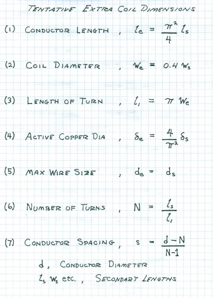
              this part here from above:
              The other method of altering the charge/discharge cycles is thru synchronous Parameter Variation. Rather than switching the energy storage elements, the co-efficients of energy storage, L, and, C, can be made variable throughout the cycle of Alternating Energy Exchange. Hereby the capacitance can vary between charge and discharge intervals, or the inductance can vary between charge and discharge intervals, and both can be varied throughout the cycle of alternating energy exchange. The magnification factor is now a complex quantity, or versor expression. Little theoretical knowledge exists on this subject.

              this is an ideal arrangement in that any load against the circuit would be met provided it could be 'tuned'. I do wonder thought if it's possible to self feed the circuit, I get the feeling it would be an infinite loop that would be highly destructive, unless balanced oh so finely,ummmm...

              Comment


              • Mind Bottling... FOUR QUADRANT THEORY OF ELECTRIC WAVES

                My God! The recent Transmissions of Mr. Dollard have been the holy grail in terms of building an actual device using his Four Quadrant Theory of Electric Waves! This along with James F Murray's work go hand in hand for the greater understanding of ELECTRICAL ACTIVITY (VA, VAR, Watts & Apparent Power) and that by OSCILLATING this quantity as opposed to specifically a voltage or a current you get AMAZING RESULTS that can either remove (work used with out radiation, heat dissipation, or transference by M or K or storage by L or C) or impart anew from the ELECTRIC FIELD and its subsequent constituents the DIELECTRIC & MAGNETIC via a changing STORAGE PARAMETER L or C (and having potentially other ways as well).

                The Transmissions, Four Quadrant Energy Exchange & The Four Quadrant Theory of Electrical Activity, are awe inspiring to me, and have truly changed my (albeit limited) perspective on electrodynamics. These used with reference to his prior works Symbolic Representation of the Generalized Electric Wave, Symbolic Representation of Alternating Electric Waves and the final chapter in Theory of Wireless Power are some very powerful tools if you have a creative, clear thinking, engineering oriented mind. Also the 1990 JBR article that Jim Murray wrote while working with Mr. Dollard, New Concepts in Power Generation, is a must read. The reason I brought up Jim Murray is because of the fact, that he is the only person I know, who has used Mr. Dollard's Four Quadrant Theory in actual designs of working machines and solid-state circuits.

                For those who would like more info on Jim Murray, here's my personal collection of files on the man:

                New Concepts in Power Generation, JBR Vol. 46, No. 2, March-April 1990, 32 pages (this was quite troublesome to get a hold of, but is LITERARY GOLD)
                Free File Hosting - Online Storage; Upload Mp3, Videos, Music. Backup Files

                Peter Lindeman Exerpt on Jim Murray. This has a link to a video of a Lecture that Jim gave.
                Free File Hosting - Online Storage; Upload Mp3, Videos, Music. Backup Files

                James F Murray Patents on his Dyna-Flux Motor/Alternator (three total):
                Free File Hosting - Online Storage; Upload Mp3, Videos, Music. Backup Files

                Here are the References used by Jim, in the video link given by Peter. These are the three articles by Nikola Tesla on the Moons Rotation about its axis.
                Free File Hosting - Online Storage; Upload Mp3, Videos, Music. Backup Files


                To Mr. Dollard,

                Thank you for all your tireless and compassionate efforts in sharing your work and understandings of Tesla, Steinmetz & Heaviside, despite your personal circumstances and seemingly rightful contempt of your fellow man (or should I say common swine of society).


                To everyone participating on the forum,

                Good luck on your coil building (I'm still getting all the parts for my build), and a very big thank you for your contributions and continued interest in Mr. Dollard and his work.

                Garrett M
                Last edited by garrettm4; 03-08-2012, 01:13 AM.

                Comment


                • Coil related questions

                  For my secondary coil calculation I came up with a 3.24mm wire diameter. That is about equivalent to a 1/8" dia wire or no.: 8 AWG size wire. Tesla, on the other hand, often used a no.:10 B&S wire or sometime he called for a no.:10 cord. If it is a no.: 10 wire or cord, it would be about .1" or 2.54mm dia. But the cord is a multistrand wire versus a .1" dia solid copper carrier. Question is, can I use stranded and insulated wire no.: 10 ga instead of the calculated no.: 8 ga solid copper. The secondary coil would probably be a taller dimension. The cost of material enters into the picture and the minimum amount to purchase around here is 100m. Any thoughts?

                  Comment


                  • The secondary coil conductor must be hollow. Number 14 wire is maximum thickness, otherwise wall depth is 0.03 centimetre. The 62% spacing is for maximum magnification factor. Otherwise use 14 gauge copper wire on secondary coil. Any larger than 14 gauge litz wire must be used to get all the copper active. This is for 1000 Kc/sec. Tesla's Colorado unit was 80 Kc/sec. At that frequency he could use 10 gauge wire because there is less of a skin effect. Here we are dealing with 1000 Kc/sec, more of a skin effect. This allowed for a 3.5 times thicker conductor material. Remember coax works as tubing as it's hollow, and equal volume/same as equal weight. Remember whatever active volume of metal you have in the secondary then determines the amount of active metal in the primary and extra coil accordingly.

                    73 DE N6KPH
                    SUPPORT ERIC DOLLARD'S WORK AT EPD LABORATORIES, INC.

                    Purchase Eric Dollard's Books & Videos: Eric Dollard Books & Videos
                    Donate by Paypal: Donate to EPD Laboratories

                    Comment


                    • Calculating Properties for Secondary

                      SUPPORT ERIC DOLLARD'S WORK AT EPD LABORATORIES, INC.

                      Purchase Eric Dollard's Books & Videos: Eric Dollard Books & Videos
                      Donate by Paypal: Donate to EPD Laboratories

                      Comment


                      • Coaxial coil material

                        Thank you Eric very much for your valuable help in figuring out what is right and what is false. Two coax cables which have similar sizes to the one used in your 1980's Longitudinal Wave video are the RG178 ang the RG316. One of the manufacturer, Wellshow, gives the following specifications.
                        RG178 - .071" insulation OD, .041" shield OD, and center conductor is silver coated copper covered steel wire, 30AWG.
                        RG316 - .10" insulation OD, .067 shield OD, and center conductor is silver coated copper covered steel wire, 26AWG.
                        The questions are:
                        1. Do we connect the center conductor to the shield?
                        2. Either way, connected or not, does the center steel wire conductor acceptable for operational purposes, i.e. possibly creating a magnetic field that could interfer with the desired coil resonance?

                        Comment


                        • Coyote like idea

                          Originally posted by Web000x View Post

                          When I spoke to Eric, he told me to let everybody know that he has finally grown sick of interacting with society. His driveshaft is still missing after many email attempts of getting a hold of the individual that supposedly has it. On top of that, the car parts that were promised to him have still not manifested. It seems like it is just easier for some people not to help Mr. Dollard rather than sacrifice a little time and effort...

                          He told me that he will be cutting ties with society as much as possible. He may write another book just for the sake of boredom as he doesn't see a laboratory becoming a reality at this rate. If there is anybody out there that can possibly do some fundraising for Eric or get in touch with him about investing in furthering his research, there is a load of equipment at a scrapyard in Morro Bay that has most everything that he would need to build a lab. Estimated cost is a couple of thousand U.S. Dollars. It would be a shame to see Mr. Dollard share the same fate as Dr. Nikola Tesla, broke and homeless (lab-less).

                          Eric, I just wanted to say thank you for everything that you have presented. I can guarantee that your efforts will bear fruit. It will just take longer than expected since none of us are properly funded for R&D. Don't lose hope yet.

                          Dave

                          It would be my hope that there could be a possibility of setting up some sort of Lab for Eric, perhaps not the multi-million dollar lab that he deserves, but perhaps a shoe-string budget Laboratory at some location, where Eric can access equipment, tools, and building materials. Unfortunately though, it seems everyone is broke, myself included. I send a little money now and then but it isn’t enough to set up a Lab. However might there yet be hope, it still exists..

                          Eric has given the design instructions and formulas (which are absolute gold in my opinion) and there is now enough information to begin immediate construction. One might say, concerning the Crystal Radio Receiver Initiative, that it’s a heck of a lot of work and money to spend, building a Tesla type crystal radio receiver, just to light up a small light bulb. However it’s actually a rather brilliant and Coyote like idea, for several reasons.

                          1st - As Eric says it will prove Tesla once and for all.

                          2nd - It teaches us how to properly construct a Tesla coil type radio system, a valuable teaching unto itself.

                          3rd - Teaches us how to receive a signal, one must know how to receive before one can begin to transmit.

                          4th - No license is required to receive an AM radio signal.

                          5th - It would be great fun to just (briefly) “pull the rug” out from under the local radio station.

                          6th – Other reasons not yet realized.

                          Obviously, each builder would select their own local radio station to tune into and build their system up for that. Learn how etc. Eventually however, given time, some money and a little experience, those whom are ready, once the systems are in place, (I.e. good grounding systems etc). I would suggest that particular frequencies be chosen and agreed upon world wide, thus to begin the possibility of transmission and reception of a Tesla Type, Non-Electromagnetic, World Wide Radio System. E.g. From the USA to Australia, or other locations around the world, where these Tesla Radio Systems are constructed, the possibility to send & receive transmissions, through the Earth at Pi over two times the velocity of light.. Something that is actually achievable & within the realms of possibility.

                          Electric farmer Dollard, has planted the seeds, they will soon spout and grow, and they are not easily up-rooted.
                          "Doesn't matter how many times you kick the coyote in the head, it's still gonna eat chickens". - EPD

                          Comment


                          • Weight of Cu Shield: RG-178

                            Originally posted by Nhopa View Post
                            Thank you Eric very much for your valuable help in figuring out what is right and what is false. Two coax cables which have similar sizes to the one used in your 1980's Longitudinal Wave video are the RG178 ang the RG316. One of the manufacturer, Wellshow, gives the following specifications.
                            RG178 - .071" insulation OD, .041" shield OD, and center conductor is silver coated copper covered steel wire, 30AWG.
                            RG316 - .10" insulation OD, .067 shield OD, and center conductor is silver coated copper covered steel wire, 26AWG.
                            The questions are:
                            1. Do we connect the center conductor to the shield?
                            2. Either way, connected or not, does the center steel wire conductor acceptable for operational purposes, i.e. possibly creating a magnetic field that could interfer with the desired coil resonance?
                            1, My understanding is that the inner conductor is never used, or connected. Free floats within the Teflon, although it acts as a "reflector".
                            2, Don't know, probably not.

                            I have actually measured weight of the copper shield within RG-178 Co-axial cable. (Not just calculated but striped 1 meter and measured on an accurate analytical balance).

                            Actual weight of Cu shield in RG-178 Co-axial cable is 3.54 grams per meter. (3.5384g)

                            I will post Cu shield weights of other co-axial cable when available (RG-316 next).
                            "Doesn't matter how many times you kick the coyote in the head, it's still gonna eat chickens". - EPD

                            Comment


                            • Weight of silver plated copper shield.

                              Originally posted by Sputins View Post
                              1, My understanding is that the inner conductor is never used, or connected. Free floats within the Teflon, although it acts as a "reflector".
                              2, Don't know, probably not.

                              I have actually measured weight of the copper shield within RG-178 Co-axial cable. (Not just calculated but striped 1 meter and measured on an accurate analytical balance).

                              Actual weight of Cu shield in RG-178 Co-axial cable is 3.54 grams per meter. (3.5384g)

                              I will post Cu shield weights of other co-axial cable when available (RG-316 next).
                              Thank you for the weight figure, this will take the guess work out calculating veights.
                              I still need an answer to my second question.
                              As far as the frequencies concerned, Eric picked 1,000Kcps, but if I do not have any radio station transmitting on that frequency near me then I suppose I can use other frequencies. How about short wave stations in the Mcps range. The important thing is the amount of power they are transmitting with and the distance to the "Tesla receiver". Do we have an equition for the power drop-off as function of distance from the transmitter? Is it simply 1/distance or 1/distance squared or some log function?
                              Last week in my post I mentioned that, we should look at the available equipment at Morro Bay. If it is only a few thousand dollar and if Eric determines that they would be useful to him, then we should make an effort to get them and store them until a lab-site is found. Somehow I have the feeling that many people on this forum (probably mostly guests) do not truly understand Eric Dollard's significance. It is like a fleeting moment, that comes and goes in a blink of an eye. Those of us who realize what are we part of thanks to Eric, should make all efforts to find a solution for Eric's situation. May be Eric's main contact should run a survey to see how much pledge is there to support this effort.

                              Comment


                              • SUPPORT ERIC DOLLARD'S WORK AT EPD LABORATORIES, INC.

                                Purchase Eric Dollard's Books & Videos: Eric Dollard Books & Videos
                                Donate by Paypal: Donate to EPD Laboratories

                                Comment

                                Working...
                                X