 Tweet
Tweet
RG316 coax cable
In Eric dollard's video on longitudinal waves, Peter Lindemann says the coax cable used had a diameter about .080". The RG316 coax is .098" dia, while the RG178 coax cable is .071" dia. The other difference is the max attenuation of the two cables. The RG316 has 22.452 dB/100' @ 750MC and the RG178 has 42.7 dB/100' @ 900MC attenuation. But because we use the shield as the conductor I don't think it matters. To measure the weight of the silver coated shield is more difficult for this reason Eric recommended the matching the surface area of coax cable shield secondary to that of copper strip primary. Both RG178 and RG316 can be purchased on Ebay for about the same price. I wonder how much difference does it make that the RG178 core is silver plated, copper clad steel and that of the RG316 core is copper.
In Eric dollard's video on longitudinal waves, Peter Lindemann says the coax cable used had a diameter about .080". The RG316 coax is .098" dia, while the RG178 coax cable is .071" dia. The other difference is the max attenuation of the two cables. The RG316 has 22.452 dB/100' @ 750MC and the RG178 has 42.7 dB/100' @ 900MC attenuation. But because we use the shield as the conductor I don't think it matters. To measure the weight of the silver coated shield is more difficult for this reason Eric recommended the matching the surface area of coax cable shield secondary to that of copper strip primary. Both RG178 and RG316 can be purchased on Ebay for about the same price. I wonder how much difference does it make that the RG178 core is silver plated, copper clad steel and that of the RG316 core is copper.


 ...etc

 , Numeric (6)
 , Watts, (7)
 , Joules (8)
 (9)
(9)  (9)
(9)  (10)
(10)  (10)
(10)  ,
, 
 ,
,
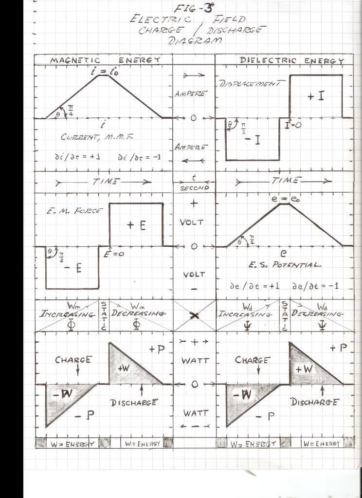
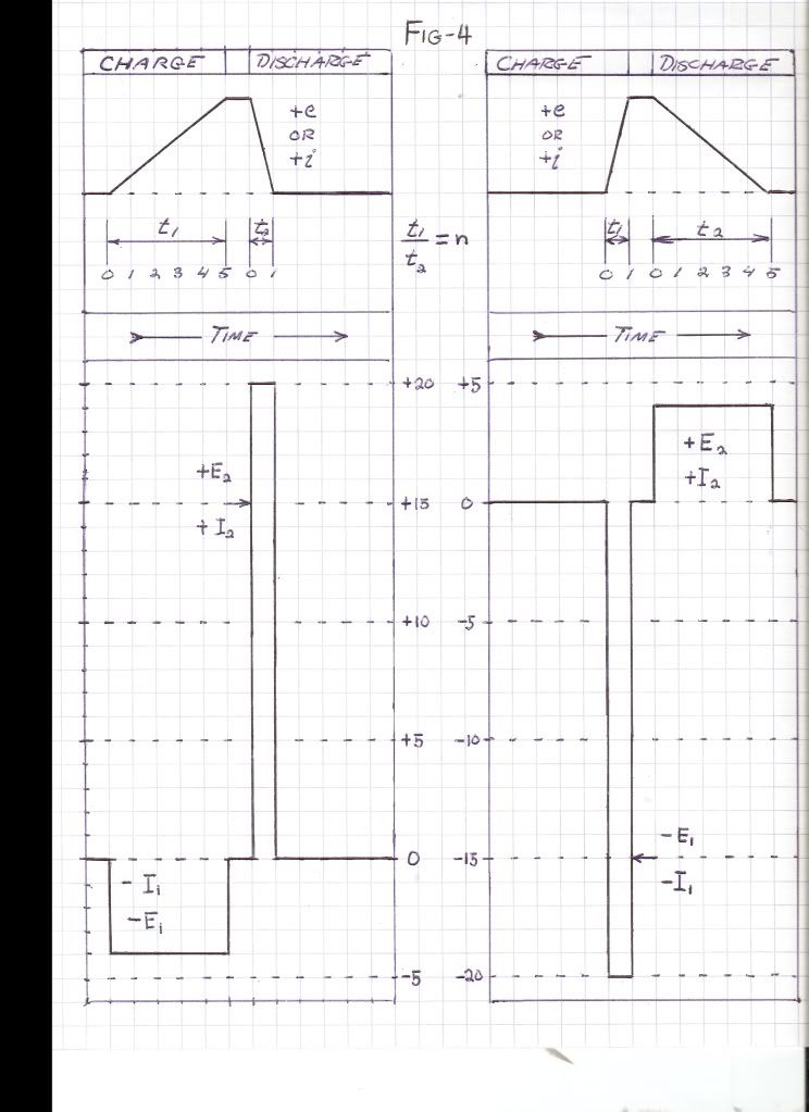
 is the charge/discharge versor operator. Substituting these expressions into the general relations of Power Flow, the magnetic,
 ,
, 
 ,
, 
 ,
, 
 ,
, 
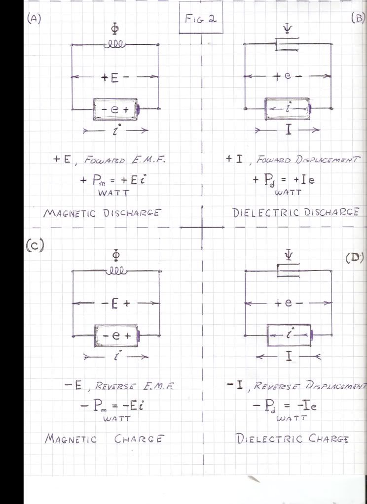
 , Versor Watts
 , Versor Watts
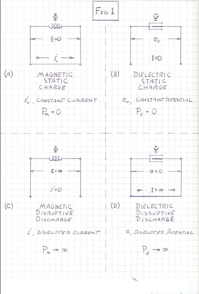
 The extra coil is equal diameter to height ratio.
Comment