If this is your first visit, be sure to
check out the FAQ by clicking the
link above. You may have to register
before you can post: click the register link above to proceed. To start viewing messages,
select the forum that you want to visit from the selection below.
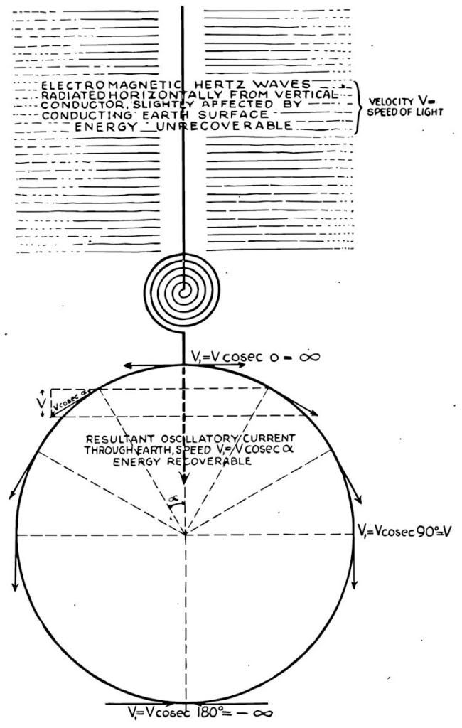
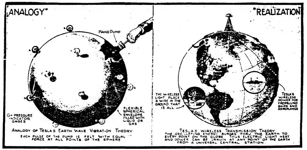
Tesla's Diagram of overground vs underground waves Hetzian/Telluric
Tesla's Diagram of overground vs underground waves Hetzian/Telluric
Note Telluric velocity, a function of angle around the earth, it is a cosecant, infinity at the poles, luminal at the equator. Pi over two is the integral "velocity"
SUPPORT ERIC DOLLARD'S WORK AT EPD LABORATORIES, INC.
Hi Eric, I'm fascinated by the hollow Earth theory.
I would be interested in how you came to your conclusion on the hollow Earth? Was it from your work in Telluric waves?
Thanks for all your work, I'm intently listening to you and respect your hard gained insights. It's rare to hear the truth these days and when it's heard, it rings a bell within those similar souls while scaring those opposed to truth.
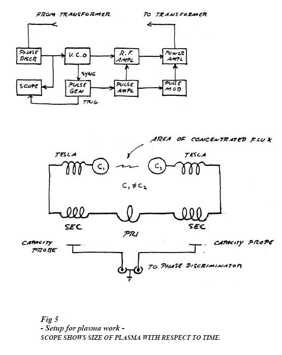
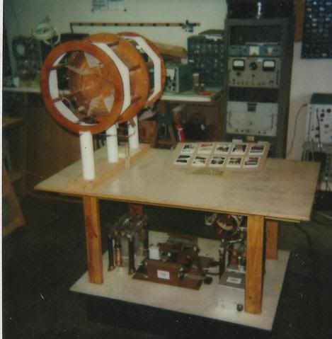
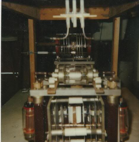
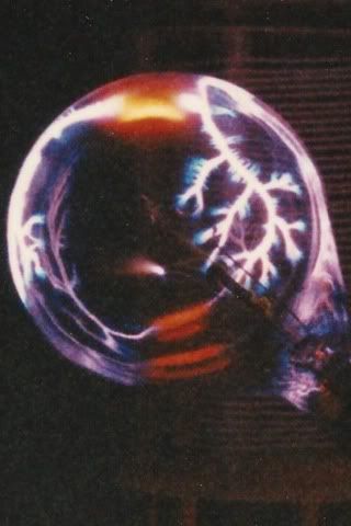
These pictures are from a Cosmic Induction Generator, that Eric Dollard built. Everything you see in the pictures was built by Eric's hand, and his assistants: Donald Lockwood of the Integraton and Michael Knotts. It was so named the "Cosmic Induction Generator" because it created "galaxies" through electric induction. (That's why the Farnsworth family adopted Eric)
It was a balanced field generator using Tesla Transformers. A burned out, incandescent light bulb was held in between the dielectric field of the out of phase extra coils. On page 15 of "Condensed Intro to Tesla Transformers" it is labeled the "area of concentrated flux." The out of phase extra coils create the central plane of superimposition from which the galaxies emerge. Everything is golden ratio, five phase fractal.
Comment from Eric accompanies the pictures.
The first picture is a schematic of the setup. It is from page 15 of "Condensed Intro to Tesla Transformers"
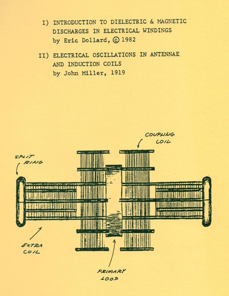
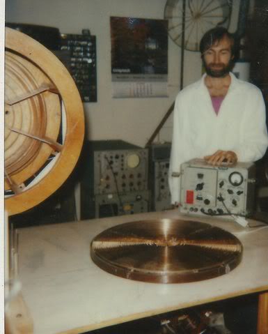
This is a blueprint of the coils, all arranged in a line. In the pictures the extra coils are separated, sitting on stands. The diagram is an exact blueprint for the number of turns. The primary details are not easy to see. Only the outside winding of the primary is visible. It was probably 2 or 3 turns, can't remember.
Primary and Secondary Coils:
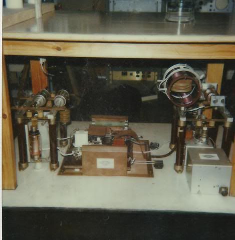
Power Supply: 10 kw vaccum tube high frequency power supply. 10,000 volts 1 ampere 2500 kilocycles
High Frequency Power supply, tubes missing from their sockets, tubes were 4 Eimac 304-TL pulse triodes from WWII radars EImac 304 TL and 304 TH power triodes represent a most effective device for producing high frequency pulses of extraordinary power
End view of primary and secondary. Note internal spiral windings are the primary. Experimental coil lays on the table
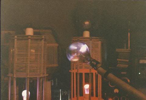
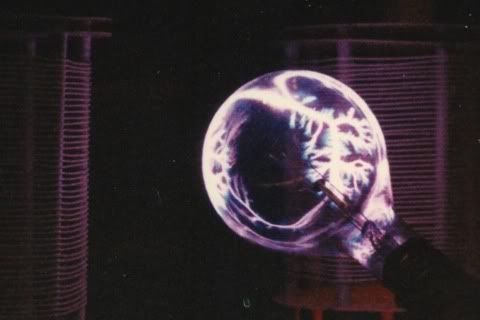
Extra coils are on legs, the primary and secondary coils are in the background. The bulb is held in between the two extra coils.
Note zone of cosmic superimposition, the orange "flamey" region this is where the creation begins. Note directly below it a comet is moving from left to right. Directly below that a streamer changing from violet to red in another cosmic superimposition . Hence a plane of cosmic superimposition passes through the center of the bulb. Here is where the galaxies are born.
Note the fractal pattern on the glass - no one else's Tesla coil does this!
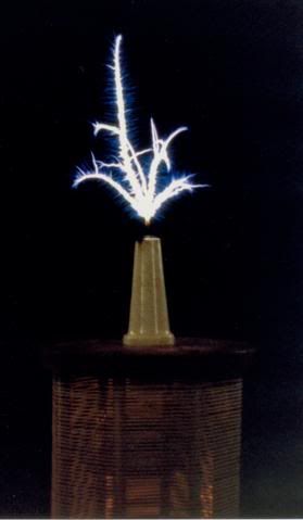
Fractal, golden ratio discharge into counterspace from extra coil. Golly Mr. Wizard why does it look just like Colorado Springs?
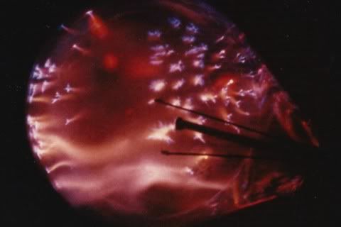
The red spot of Jupiter in a burned out incandescent light bulb. The light bulbs were from the L.A. Departent of Water and Power.
All the equipment in the photographs were embezzled by George Flores in Los Angeles California. He was someone else that showed up to "help" Eric Dollard. Everyone wants to help "themselves" to Eric. Like the martians in the movie "Mars Attacks" -the aliens were announcing "We are your friends" as they start exterminating the humans.
Borderlands embezzled all the funds for the safe place to move the equipemt to. The funds were sent by Josh reynolds. Eric was told "We need the money more than you do".
The Cosmic Induction Generator is truly fascinating. It really seems to show the fractal nature of reality. Planets and comets appearing...I wonder what else it would show. I am curious as to what the original purpose was in constructing it? Is that pure dielectric energy forming inside the bulb?
Eric, another couple questions. The use of coax cable and inter turn capacitance.
Basically given the feature of interturn capacitance of the flat wire Tesla used in the primary, if using coax cable; being sheathed in teflon and thus a good dielectric it's increasing the capacitance over air, how does this effect the LC of the coil? also since coax cable suppresses inductance is this by design as needed to enhance the longitudinal wave? Then also wouldn't that mean that the secondary is not mutually inductive but reactive via capacitance?
Is there a similar phenomenon to current voltage lead/lag phase occurring in the inter turn capacitance?
This is also why the mass of the conductor is critical to being matched right? is there more of a correlation to the material? copper vs silver etc.. Do you think there is a correlation to the materials affected by transmitted vs reflected rays and if a material that is more affected by transmitted rays being more conductive to transmitting longitudinal waves
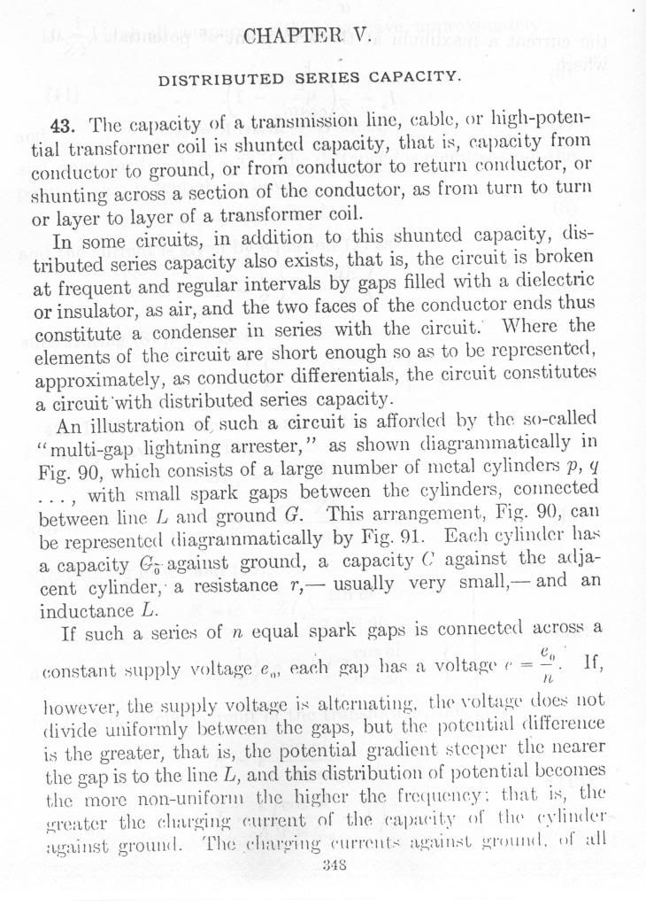
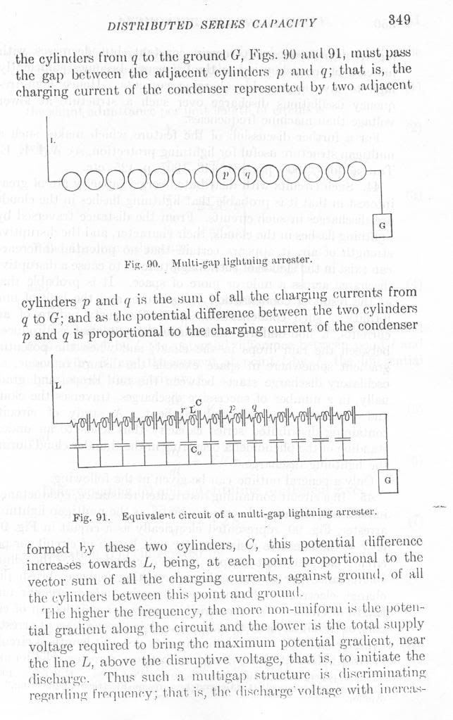
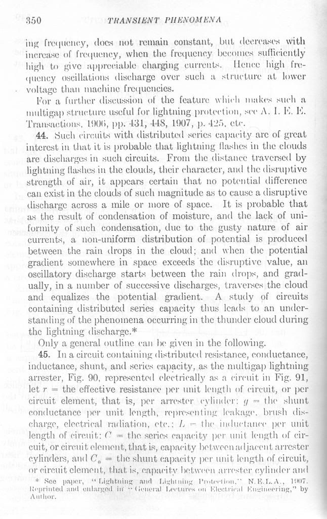
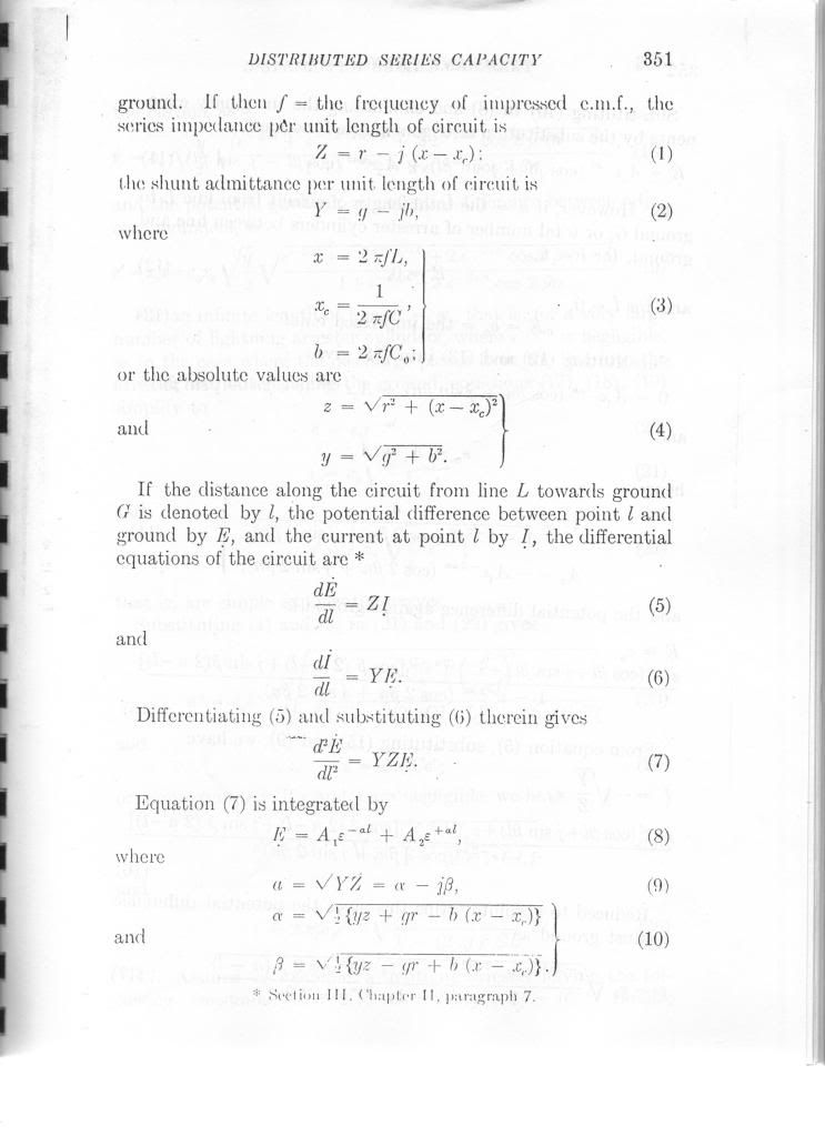
From "Electric Waves, Discharges, and Impulses", C.P Steinmetz, p67
Relation of Magnetic and Dielectric Energy Transient
@Eric
When building a TMT where should we place the nodes and how many are optimum for proper operation? The phase angles for each of the coils?
I presume that could easily be accomplished by measuring the reflected voltage for each coil or even using an swr meter between them to zero in?
From what I gather it sounds like odd number 1/4 lamda, 3/4. 5/4 and so forth for the total? I believe the patent stated the whole thing should be 1/4 and I presume swr = 1 at the ground side.
I would think that 1/4 lambda for the whole thing would present some interesting tuning hurdles for self resonant coils. not sure if I am making sense here.
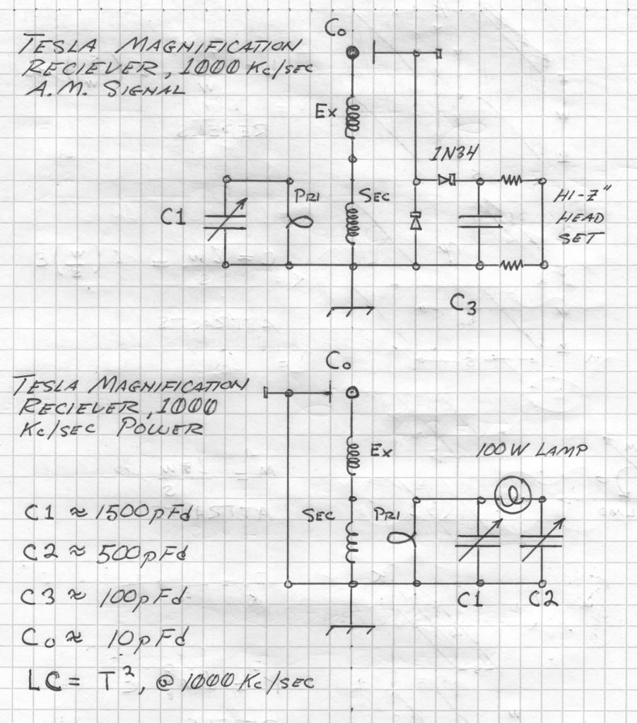
For the diagram shown the coil dimensions are missing, number of turns, etc. A good ground is essential for these kinds of devices. 16 Ground rods in a 10 to 20 foot radius circle, connected to a single ground rod at the center(17th rod), this connection being 10 gauge wire. Dry sand or rock will not ground, so this requires 80, each 14 gauge wires in a 30 foot diameter circle in a star radial configuration, to a center terminal. Without these groundings a Tesla Transformer cannot properly operate, but some "HI-Z" sets may.
The objective here is to scale the "Crystal Set", a step at a time, into a Tesla Transformer for the reception of medium wave band, 300 - 3000 kilocycle A.M. broadcasts. No license is required for this and the broadcast station provides the power.
And this objective cooperates with the primary objective. That is; Who will be the first ham to disprove Einstein's theory? An International contest, but who will sponsor it, Iran maybe?
We have the good fortune in the "Crystal Set Initiative" that, in theory at least, a quarter wave A.M. broadcast tower, and its 120 quarter wave ground radials, must emit a pair of waves as shown by Tesla in his basic diagrams.
Hence it can be seen that a pair of waves are engendered by this transmission system. (Tower and Star Radials). One wave, Hertzian, is the over ground wave, the other wave, Telluric, is the under ground wave. These two waves arrive at the point of reception in their own distinct time frames, giving rise to a difference in phase. Hence, multiple rings of interference patterns are produced. Since the Hertzian portion, over ground, time frame is based upon the velocity of light, then the Telluric portion, under ground, time frame gives the Telluric velocity. Two crystal sets, one over ground, one under ground, and a basic oscilloscope , that simple. I have done this at Landers.
Concluding, a Tesla Magnification Transformer, properly proportioned can, in theory, actually draw power from a local 50 kW station. Several hundred watts of power reception is likely. This would prove Tesla once and for all. No antenna, just a good ground, and a nice and bright 100 watt light bulb.
This would overturn physics more than any billion dollar C.E.R.N. project. A ham radio operator overturns Einstein for 100 bucks. What a concept.
Read,
Tesla, "The True Wireless"
Tesla, "System of Concatenated Tuned Circuits"
Dollard, "System for the Transmission and Reception of Telluric Electric Waves"
A.R.R.L. "Radio Amatuers Handbook". Chapter "H.F. Transmitters, & Tank Circuits"
73 DE N6 KPH
@Eric
my first thought is tune up to 60 cycles! ha! Which if course is illegal but a fun thought none the less! LOL
So the 10pf provides a feedback loop? Do you have a pic by chance of the physical configuration required for that?
Also I meant to ask you, that in your sbarc talk you mentioned that between the 2 transmitter and receiver capacitive inductors (spheres) it forms an extremely tight DC beam. Could you elaborate on how that occurs? Does it try to form a channel like lightning would before and actual arc jumped? I am very interested in the mechanics behind that phenomena.
Thirty turns are about right on the extra coil.Any teflon covered co-axial cable is fine, but remember the copper weight of the primary, secondary, and extra coil MUST all be equal, this is important. Metal lost to the "skin effect" must be taken into consideration. Rule:
2 inch thick 60 cycle, .2 inch thick 6000 cycle, thickness inverse to the square root of the frequency (flat stock is best)
Thank you for all this info Eric. Is there anything you can tell us about the relation of the secondary to the extra coil, like particular size, number of turns or wire length ratios? In the Colorado Springs Notes page 190-191 Tesla shows six diagrams, Fig. 4 being of most interest to me, stating that a 1/4 wavelength secondary and 1/2 wavelength extra coil produce the greatest pressure on the ball in this configuration. So I suppose the question is, is that all there is to it?
Also would it be a big disadvantage to use single strand copper wire rather than teflon covered co-axial cable?
This drawing appears to be based on Tesla's statements in the 1923 Foreclosure Proceedings, while it is a mystery where the idea of those "radial tunnels" comes from:
Nikola Tesla for Defendant---Direct.
A. Yes. You see the underground work is one of the most expensive parts of the tower. In this system that I have invented it is necessary for the machine to get a grip of the earth, otherwise it cannot shake the earth. It has to have a grip on the earth so that the whole of this globe can quiver, and to do that it is necessary to carry out a very expensive construction. I had in fact invented special machines. But I want to say this underground work belongs to the tower.
By Mr. Hawkins:
Q. Anything that was there, tell us about.
A. There was, as your Honor states, a big shaft about ten by twelve feet goes down about one hundred and twenty feet and this was first covered with timber and the inside with steel and in the center of this there was a winding stairs going down and in the center of the stairs there was a big shaft again through which the current was to pass, and this shaft was so figured in order to tell exactly where the nodal point is, so that I could calculate every point of distance. For instance I could calculate exactly the size of the earth or the diameter of the earth and measure it exactly within four feet with that machine.
Q. And that was a necessary appurtenance to your tower?
A. Absolutely necessary. And then the real expensive work was to connect that central part with the earth, and there I had special machines rigged up which would push the iron pipe, one length after another, and I pushed these iron pipes, I think sixteen of them, three hundred feet, and then the current through these pipes takes hold of the earth. Now that was a very expensive part of the work, but it does not show on the tower, but it belongs to the tower.
So, Tesla does not say anything about radial pipes. He talks about pushing the iron pipe, one length after the other.
So, could it be that these 300 feet are supposed to be an additional 300 feet, so you would end up at 120 + 300 = 420 feet depth eventually?
Then we would get a total length of the main pipe of about 600 feet, which is incidentally also what he calculated with in earlier designs, designs that would become way to large (hight) to actually build:
In annexed sketch [See Fig. 4.] a terminal C in form of a roof is supported on conducting supports L1L1. Terminal C1 is adjustable and in contact with structure of roof, or terminal C1. A resonating system C2ℓSE discharges with C1 and produces oscillations in system CL1L1E1E1.This arrangement obviates necessity to support roof or terminal C on insulated supports.
Now in a sketch or scheme the difficulty will be probably to get the oscillations of the free system CL1L1E1E1 slow enough to be very effective in transmission through earth as in my system. The length of conductors in the free system should be λ/4, and the length of the discharging current should be 3/4 λ or n/4 λ eventually, n being uneven number.
[...]
Calculated it would appear that the supports L would have to be about 600 feet. The arrangement would be OK with quick oscillation. The self-induction of a straight conductor is L' = 2l'[loge (2l'/r) - 0.75]. Now, take /'= 300 ft = 9000 cm. If we want to use iron pipes 4" diam. r = 5 cm. Then 2l'/r = 3600 and from this I find L' = 134,000 cm. Again taking the length 600 ft we would get inductance probably 268,000 cm. To get lower frequencies, evidently in above scheme self-induction must be increased.
An interesting detail on this Anderson drawing is that the mains power is fed to the bottom of the shaft, suggesting that the transmitter transformer must have been positioned at the bottom of the 120 feet deeo shaft, a shaft that has been plated with iron.
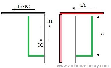
The green sleeve in Figures 1 and 2 acts as a transmission line, that is short circuited at the end. From Gauss's law, it is (basically) true that the current on the inside of the outer arm of the bazooka (green line) must be the opposite of that flowing on the outside of the coax (grey line). Hence, the current IC actually sees a short-circuited transmission line. If the length L of the sleeve is chosen to be a quarter-wavelength (at the desired frequency of operation), then the impedance that the current IC sees is infinite (this is the principle of a short-circuited quarter-wave transmission line - see the impedance page for a brief introduction to transmission line theory).
So, if you think away the coax core, then you would essentially have a structure that keeps the current (== magnetic component) above the bottom of the shaft in Tesla's case and therefore the only component that can propagate along the 300 feet 1/2 lambda iron "earth grip" starting at the bottom of the shaft would be a longitudinal dielectric wave....
So, we would then have 4 sections:
1. A capacitive load / wave reflector on top, a) to have a reference potential to push against and b) to have a wave reflector preventing longidudinal radiation along the length of the antenna/resonator away into space;
2. 1/4 lambda whip antenna above ground;
3. another 1/4 lambda section, with a sleeve balun, below ground;
4. a 1/2 lambda longitudinal transmitter antenna going deeply into the earth.
@Eric: what do you think??
Update: This balun / short circuited transmission line thing may also connect to what Edwin Gray was doing:
Thank you for all this info Eric. Is there anything you can tell us about the relation of the secondary to the extra coil, like particular size, number of turns or wire length ratios? In the Colorado Springs Notes page 190-191 Tesla shows six diagrams, Fig. 4 being of most interest to me, stating that a 1/4 wavelength secondary and 1/2 wavelength extra coil produce the greatest pressure on the ball in this configuration. So I suppose the question is, is that all there is to it?
Also would it be a big disadvantage to use single strand copper wire rather than teflon covered co-axial cable?
@Eric
those notes are a bit confusing.
If he wants high voltage on top you would think that the secondary would be 1/2 wave and the extra would be 1/4 wave. Exactly reversed? At least from my version of obvious LOL
I do not see that working properly the way it is written. It seems there should be a voltage node, (ie swr = 1:1), on the top and bottom of the secondary and on the bottom of the extra coil for proper function?
so it would seem the secondary should be 1/2 lmbda
and the extra coil 1/4 lambda
that is presuming they are in series with each other
If I am screwed up in my understanding so be it, maybe Eric can shed some light on this.
Eric, another couple questions. The use of coax cable and inter turn capacitance.
Basically given the feature of interturn capacitance of the flat wire Tesla used in the primary, if using coax cable; being sheathed in teflon and thus a good dielectric it's increasing the capacitance over air, how does this effect the LC of the coil? also since coax cable suppresses inductance is this by design as needed to enhance the longitudinal wave? Then also wouldn't that mean that the secondary is not mutually inductive but reactive via capacitance?
Is there a similar phenomenon to current voltage lead/lag phase occurring in the inter turn capacitance?
This is also why the mass of the conductor is critical to being matched right? is there more of a correlation to the material? copper vs silver etc.. Do you think there is a correlation to the materials affected by transmitted vs reflected rays and if a material that is more affected by transmitted rays being more conductive to transmitting longitudinal waves
I'll just re-quote myself to edit the last bit here. Not mass but surface area.
Also, in one of Tesla's lectures he makes specific mention of the need to reduce capacitance in the coil windings by the use of certain wire insulation but at the same time is very explicit in the use of oil for the insulating dielectric and heavy insulation, which seems counter productive as that would in fact increase the capacitance and the tension of Psi, an effect he was after correct? If there is a specific reason for the difference in capacitance location its not fully explained. The use of the coil also being completely enclosed in a sealed zinc box to increase the capacitance as well is interesting and not touched on in his notes significantly.
It would seem then the nature of the turn capacitance is to overcome the self induction of the coil. which brings up again the nature of mutual capacitance and not induction.
A primary coil of coax or braided wire would increase the skin effect via surface area and the capacitance would be the mutual link to the secondary coil of one with specific inter-turn capacitance and suppressed self induction. it would seem then that the goal is an oscillating Psi field of extreme frequency to raise potential while avoiding the magnetic field that would reduce the effect. a self induced capacitor with negligible resistance and FTL transmission.
 Tweet
Tweet


 , the Cosmic Induction Generator post was awesome with all the original photos.
 Which if course is illegal but a fun thought none the less! LOL

Comment