 Tweet
Tweet
Originally posted by dr-green
View Post
-
Thanks! Now everything is clear! Very good explanation. -
Hi,Originally posted by Alexg800 View Post
I only would like to ask the following:
Your formula lo = 1/4*0.78*c/f
The formula in the calculation lo = 1/2Pi * c/f
There is a difference in the results so as
1/4 * 0.78 = 0.195;
1/2Pi = 0.159
What to use?Comment
-
Sincerely,
Aaron Murakami
Books & Videos https://emediapress.com
Conference http://energyscienceconference.com
RPX & MWO http://vril.ioComment
-
Use the latest one, Lo = 1/4*0.78*c/FOriginally posted by Alexg800 View Posthttp://www.teslascientific.com/
"Knowledge is cosmic. It does not evolve or unfold in man. Man unfolds to an awareness of it. He gradually discovers it." - Walter Russell
"Once men died for Truth, but now Truth dies at the hands of men." - Manly P. HallComment
-
-
Live call with Eric Dollard
Starts in 24 minutes - today May 1st.
1. Dial: 1-857-232-0155 at the time you set
2. Enter the Conference Code: 582590Sincerely,
Aaron Murakami
Books & Videos https://emediapress.com
Conference http://energyscienceconference.com
RPX & MWO http://vril.ioComment
-
Gold Terminal Capacity
Eric has mentioned that the element gold (Au) has the unique property of having direct contact with the Aether, (Counterspace)? This due to the fact that gold is an inert substance, forms no oxide layer, film or barrier and is also an excellent conductor.
Acquired glom from work are quartz tubes with gold plating on the internal surface. These used gold tubes are no longer fit for purpose due to the gold wearing off, or thinning out from the very ends which ruins them optically.
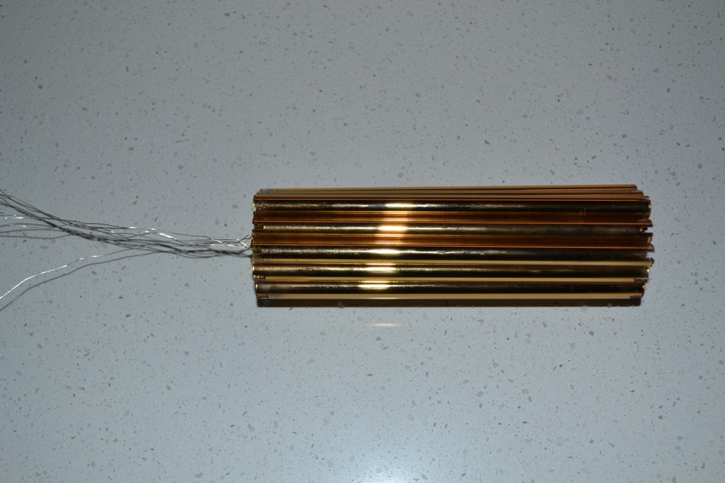
As the tubes are quartz and the gold is on the inside, they can be brought together to form a capacitive structure. One end of each gold tube has a silvered wire connected to the gold via compression to form a good contact.
The combined gold tubes have a total surface area of about 627cm2, or if rolled out flat could form 25cm x 25cm sheet approximately. The isotropic capacity of this configuration is still being determined and measured.
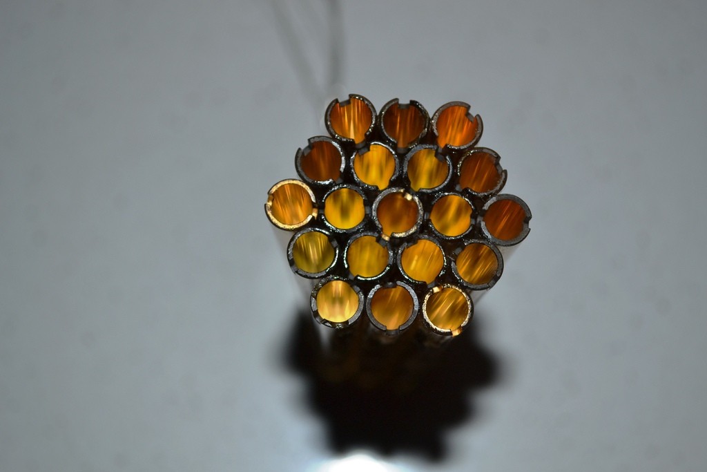
The array of gold tubes consists of 19 tubes, configured in a �flower of life� formation.
This structure is to be used as a terminal capacity for my Tesla Transformer.Last edited by Sputins; 05-11-2016, 10:19 AM."Doesn't matter how many times you kick the coyote in the head, it's still gonna eat chickens". - EPDComment
-
EMF Distribution
An effort was made to discover the EMF distribution along the 1/4 wave resonant coil structure of three different coil forms. Unexpected results were shown, that is, an uneven potential distribution up the coils.
Using a fluorescent tube to probe for the EMF node or distribution along the resonant coil does not provide a good view of the situation as the relatively large tube responds to the broader sweep of the field, one could say it has a large aperture. It does not define the finer local condition of the turn to turn EMF. The tube also has a detuning effect on the resonant coil structure when it gets to close to the coil.
Having a bag full of small neon bulbs handy afforded a series of these bulbs to be attached up the length of each coil in order to pinpoint the local turn to turn dielectric potential. The leads were removed from each bulb and the glass end was hot glued to the coil as shown in the following images. This worked out well to graphically display the dielectric potential distribution along the coil when energized at the resonant frequency.
Starting with the 4.5 x 5 inch coil of 120 turns, # 24 magnet wire. Then testing a 9.5 X 9 inch coil of 58 turns, # 11 magnet wire and finally a 19 x 3.5 inch coil of 20 turns, # 11 magnet wire. More time was spent on the 19 inch 20 turn coil as it represents the proper aspect ratios expressed in Professor Dollard�s recent transmissions concerning single frequency telluric transformer coils.
The coils were mounted about 24 inches above the floor in the lab. The neutral current was measured at the base of the coil and at the ground connection on the floor. The current transformer for measuring the neutral current is shown in the images. Each coil was tested with and without an elevated capacity. The �E� field sensing plate was 30 inches out from the top of the coil structure being tested. Basic data is given on each image. The important point of observation is the luminance level and position of each bulb.
In all cases with each coil tested there is a high potential dielectric field at the lower few turns then a drop in potential at the top of the lower quadrant, then a rise in potential toward the top of the coil. These test had the coils tuned to the base resonant frequency detected by a simultaneous peak in the grounded neutral current and secondary E field. Even so, distortions in the expected 1/4 wave EMF distribution were observed.
With regard to the observations made with the 19 inch coil. A magnetic field probe was made up from a .75 by .125 inch bobbin wound with 8 turns of #26 magnet wire. This winding was loaded by a 2 volt incandescent bulb taken from a mini Christmas Tree light string. See pictures. This probe indicated high electromagnetic fields at the location of the low dielectric field point of dark neon bulbs. Curiously, the only location that the magnetic field was strong enough to light the lamp was on the inside of the coil winding as shown in the picture. Outside the coil radius there was no effect!
The large elevated capacities used did seem to make the potential node move slightly higher up along the coil as professor Dollard suggested. However the neutral series (ground terminal point) impedance did not change significantly when the elevated capacity was added. Nor did the impedance of the primary tank circuit as the matching network adjustments needed little readjustment after installing the elevated capacity and sweeping down to the lower resonant frequency..
I encourage you all to try this test set up with the small neon bulbs on your coils. It would be of particular interest to see how the neon bulbs would would display on a flat spiral coil form?
An input power level of around 10 watts worked well for these test.


Comment
-
If anyone can seeriuosly answer this question i might try to stay but, why do you guys, eric dollard, think that people will go nuts if someone is alerted to danger for after greenpeace came for you and got you to agree with them after you said the opposite before, if this isnt just for scamming people? because reason im leaving is the free nergy section is full of vortexes, which are concepts threads while they con people for money on making videos oooh. go watch your tv guys. and there are elite, not elite threads. or something else. if you are unable to speak just stare at the tube or a loaded gun in your mouth for fun, do that.
because hte idea that alerting people of danger or a problem and they panicking is a scare-tactic in itself. why are there cop cars with blue lights for? but i guess you guys would believe in a GOD that carries guns while everyone else doesnt too. And cops are such great, you kow, right? and theyre so trained and literally are the most retarded people in it. The biggest ego maniacs, the biggest phycopaths, trying to teach 13 year olds to tell on each other and rat behind each others back. Seriuosly half the police force in my area i know from school and where MENTALLY RETARDEd and where taught by my dad who taught that class.
and thats how it is everywhere, its the status quo.
you knw as your asnsewr to me. and heres the real kicker, why do you think everyone will panic whe, the people who you sell this stuff off to, will use it and destroy everybody and themselves with it, but you think oh everyone will panic.
there not an organization.
any good answers to that??Comment
-
Macak, (not that I'm a judge), but your work is excellent. Thanks for sharing your work and findings..
Keep at it...
I will too...
Sputins."Doesn't matter how many times you kick the coyote in the head, it's still gonna eat chickens". - EPDComment
-
I'm back
I'll be here in front of the computer so I can answer questions.
I'm here at Aaron's putting my presentation together for the conference.
"Presentation: ELECTRICAL TRANSMISSION IN MULTIPLE COORDINATE SYSTEMS – A continuation of the Extraluminal Transmission Systems of Tesla & Alexanderson presentation from the 2014 Energy Conference available at The Extraluminal Transmission Systems of Tesla and Alexanderson by Eric Dollard. This will be highly mathematical but will still use only basic algebra. You will get a very detailed analysis of the Alexanderson System as well as learning about wave propagation in coordinate systems. Physicists use the term dimensions so in other words, it will be about wave propagation in other dimensions that are outside of the velocity of light. The analog computer network systems will be a central figure in this presentation. If you are a fan of the old Borderland videos with Eric’s presentations on the analog longitudinal networks, then you will not want to miss this!"
Posted at: 2016 Speakers ? 2016 Energy Science & Technology ConferenceLast edited by Aaron; 06-29-2016, 10:12 PM.SUPPORT ERIC DOLLARD'S WORK AT EPD LABORATORIES, INC.
Purchase Eric Dollard's Books & Videos: Eric Dollard Books & Videos
Donate by Paypal: Donate to EPD LaboratoriesComment
-
Silver Teflon Coax ?
Howdy T-rex,
I discovered that most of the silver teflon coax cables have a silver coated copper clad STEEL center conductor. This raised a big red flag to me for using this wire that has steel in it for winding the secondary of a resonant transformer. The two teflon coax cables I had on hand did have steel in them as they clung to a permanent magnet. See image. I looked on a few speck sheets for silver teflon coax and there are few that do not have steel in the center conductor. Those that have no steel are very pricy and hard to find.
Can you expound a bit on various wire type options for use in a resonant transformer secondary wound for the Crystal Radio Initiative where there is little voltage generated verses the Cosmic Induction generator windings that are run at higher power levels?
Thanks and good luck with your presentation!
Macak

Comment
-
The Long Path to Understanding Gravity
G�day Eric,Originally posted by t-rex View Post
Good luck with your Presentation at the Conference! - I look forward to viewing it myself when the video is released. Even better would be to see the presentation live.
While you have a few days or so near a computer, I thought I�d suggest to you to have a look at the following, found on Youtube:
"The Long Path to Understanding Gravity� - Wallace (Wal) Thornhill, Electric Universe Conference 2015. - It is an hour long presentation.
https://www.youtube.com/watch?v=YkWi...8x3dI-mLbU1YCD
If you don�t have a lot of time, then start at the 34:30 mark, but the whole thing is worth a view if you have the time.
Wal Thornhill, (Auzzie Scientist, Plasma Physics) One of the Electric Universe Theory�s leading personalities at the moment. holoscience.com | The Electric Universe | A sound cosmology for the 21st century
In general, Wal says many of the same things you have spoken about, so there is some agreement in many areas:
Anti-relativity (Einstein)
Aether
Faster than Light Propagation
Gravity inside the Earth being repulsive. (May give rise to a neutral zone in between, hence a Hollow Earth Theory could be possible.
Some disagreement may occur however, over Matter and Mass and the composition of electricity etc. (Wal not being exposed to the Four Quadrant theory of Electricity as far as I know).
But it is good to hear another scientist in support to some of the same things you have mentioned previously. It would be exciting to see Eric and Wal in a room discussing EU Theory, ideas and opinions..
Sputins.Last edited by Sputins; 06-29-2016, 04:27 AM."Doesn't matter how many times you kick the coyote in the head, it's still gonna eat chickens". - EPDComment
-
Mr. Dollard,
I am trying to understand machines operating under the phenomena of dielectric parameter variation.
For example the Chris Carson rotary electrostatic converter:
http://www.energeticforum.com/eric-d...html#post73799
We know that in a condenser, the electric field lines exert a perceptible force on the condenser plates. The Van de Graaf generator, for example, loads its input shaft as a result of this:
SCIENCE HOBBYIST PAGE: VAN DE GRAAFF GENERATOR FAQ
"As the belt is cranked along, these opposite charges fight the belt's motion. They attract each other, they "want" to leap together and rejoin. But the belt draws them apart, it uses force to separate them farther and farther, then it deposits the charge on the distant sphere and leaves the opposite charge in the earth. If you've ever tried turning a hand-crank VDG machine, you can feel the crank becoming slightly more difficult to turn as the machine charges up. Mechanical work is being converted into stored electrostatic energy as the positive and negative charges are being pulled far apart. You're mechanically charging a capacitor. "
Assuming this to be correct, it would seem that the Chris Carson device would also load its input shaft in proportion to the work being done, would it not?Comment
-
field lines only
3 related questions for Eric:
1. We've got the general idea for how a Conduction Current field line looks (closed loop filling space orthogonal to the conduction vector,) but what does a Displacement Current field line look like?
2. This one's a bit more difficult to articulate so I'll ask it from a few angles:
2a. What is the Dielectric Potential's corollary to the Conduction Current's "Displacement" variant?
2b. if Displacement Current gives rise to Dielectric Potential, what gives rise to Conduction Current?
2c. if Displacement Current charges Capacitors, what kind of Potential charges Inductors?
3. With the answer of question 2 being represented as [XYZ]: We've got the general idea for how a Dielectric Potential field line looks (straight line terminating in counter-space parallel to the potential gradient,) but what does a [XYZ] Potential field line look like?
Hope this makes sense!Last edited by Shanjaq; 06-30-2016, 11:02 AM.Comment
Comment