Announcement

Collapse
No announcement yet.

Eric Dollard

Collapse
This is a sticky topic.
X
X
 
  • Filter
  • Time
  • Show
Clear All
new posts

  • Wire type

    Hi Dr-Green:

    Do you use Litz wire for your coils? If you do, what is the strand count and the gauge of each strand? In general, would the use of Litz wire for coils be beneficial do to the high frequencies at which these experiments are being run?

    Comment


    • Originally posted by Nhopa View Post
      Hi Dr-Green:

      Do you use Litz wire for your coils? If you do, what is the strand count and the gauge of each strand? In general, would the use of Litz wire for coils be beneficial do to the high frequencies at which these experiments are being run?
      The 15% secondary is wound with 2x 22 SWG I think, but the only reason for that was to reduce the gap between each turn and I had plenty of 22 SWG at hand. Coils built since then have had the conductor diameter chosen on the basis of the spacing alone.

      I think this came up before though, as well as using copper strip. So in that respect it's probably "better" because the copper inside the wire isn't doing anything. But this is why Eric recommends the coax.
      http://www.teslascientific.com/

      "Knowledge is cosmic. It does not evolve or unfold in man. Man unfolds to an awareness of it. He gradually discovers it." - Walter Russell

      "Once men died for Truth, but now Truth dies at the hands of men." - Manly P. Hall

      Comment


      • I am measuring what I expect to see and it is grounded with copper in the garden and the electric field is max on top. I see no point in distrusting the measurement as I repeated many times with different testcoils same result just as expected.

        I will try to post the resonance spectrum in short. It is completely different from a normal transversal dipool antenna. the harmonics are to the left mainly. It behaves like the simulation of a longitudional network basically.

        Oh and the lower internal resistance 6080 tube makes the pi network much easier to handle. It is not even needed anymore. Next step will be to put the 6sn7 in front of the 6080. My voltages still are very low but than I have to take more care of the environment.
        Last edited by orgonaut314; 06-26-2015, 09:33 PM.

        Comment


        • Originally posted by orgonaut314 View Post
          I am measuring what I expect to see and it is grounded with copper in the garden and the electric field is max on top. I see no point in distrusting the measurement as I repeated many times with different testcoils same result just as expected.

          I will try to post the resonance spectrum in short. It is completely different from a normal transversal dipool antenna. the harmonics are to the left mainly. It behaves like the simulation of a longitudional network basically.

          Oh and the lower internal resistance 6080 tube makes the pi network much easier to handle. It is not even needed anymore. Next step will be to put the 6sn7 in front of the 6080. My voltages still are very low but than I have to take more care of the environment.
          Do you have details on the coil like design frequency, luminal frequency, conductor length, dimensions etc.

          You say the current is max at the free end but have you measured the potential?

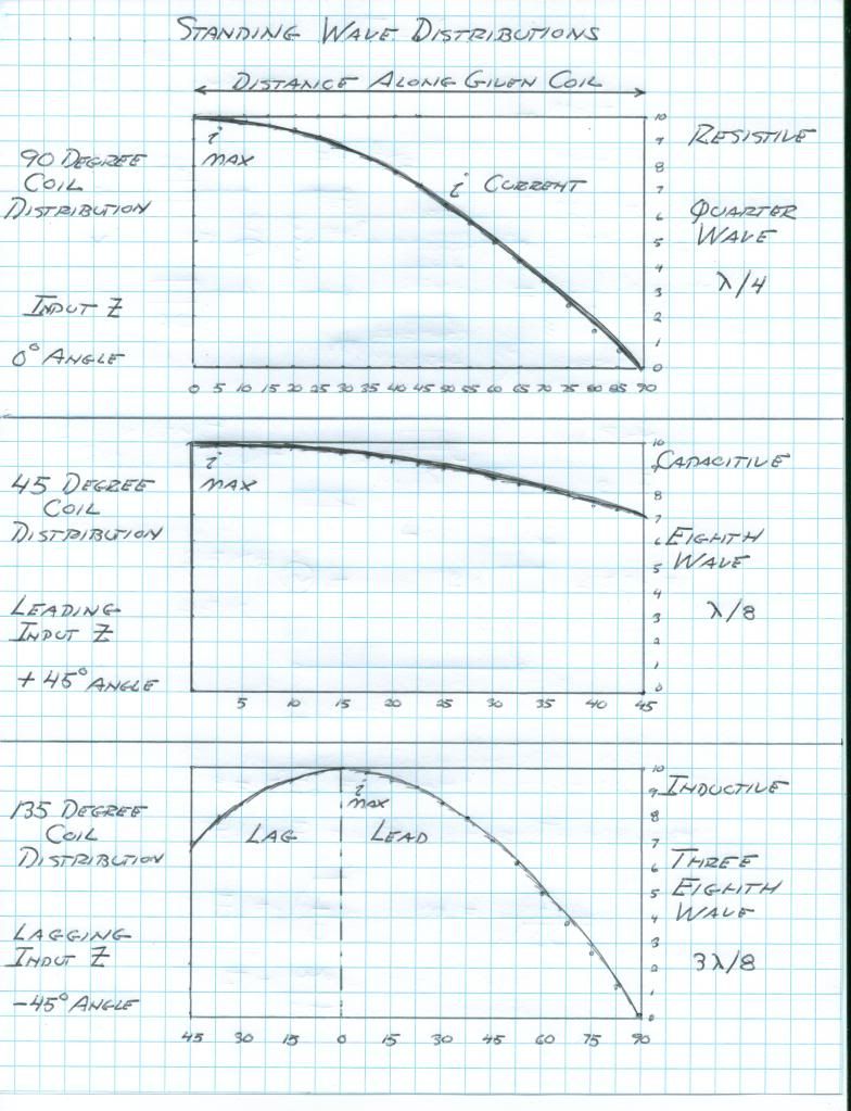
          A dipole antenna is a 1/2 wave antenna, because it has two (split) poles with the oscillator in the middle. Standard 1/4 wave distribution should be like this, which is what I always see except in the case that it's not resonating in 1/4 wave

          http://www.teslascientific.com/

          "Knowledge is cosmic. It does not evolve or unfold in man. Man unfolds to an awareness of it. He gradually discovers it." - Walter Russell

          "Once men died for Truth, but now Truth dies at the hands of men." - Manly P. Hall

          Comment


          • You keep posting that Marconi antenna. I can find other pictures of dipoles like this one.


            Understanding Antenna Specifications and Operation | DigiKey

            It is a simple transmission line. The Tesla coil is not a simple transmission line. It does not have the same resonance characteristics.

            Comment


            • I keep posting the Marconi antenna because that's what the distribution should look like. It's a monopole antenna, 1/4 wave. Note the location of the ground plane and VIRTUAL "image antenna". Dipole is 1/2 wave.
              http://www.teslascientific.com/

              "Knowledge is cosmic. It does not evolve or unfold in man. Man unfolds to an awareness of it. He gradually discovers it." - Walter Russell

              "Once men died for Truth, but now Truth dies at the hands of men." - Manly P. Hall

              Comment


              • No that is not what it should look like. I give reasons why, you do not. The picture of the dipole shows 2 1/4 transversal wave antenna's. It shows I and E just like your 1/4.

                My point is both are transversal. Eric's antenna is longitudional.

                Read that again.

                Eric's antenna is longitudional. It would be transversal if the capacity between the windings is very small. Perhaps you have to much space between the windings? I use litze. Very good because it also minimises the eddy currents in the wires. Perhaps you have build a normal antenna? I have used the capacity between the winfings that constitute a second current to the top. The sum of these currents act different than a long wire. There is not even a wave. The wave has reversed harmonics Eric calls it a wave in counter space.

                It should not look like a normal stretched wire antenna unless the capacitive coupling between wires is very small.

                I will not repeat this point more times as I did repeat it several times now with a ****load of reading material and simulations.

                Comment


                • I made a simulation with very small vallues for the mutual capacitance and the mutual inductance. Not surprisingly the coil behaves transversal now.

                  The maximum resonance is the first and I plot the current in coil 4 (green) and coil 13 (red). The current in coil 4 is bigger than in coil 13. The magnetic field is now in space disjunction with the electric field.

                  This all is very difficult to understand and I will start a new thread with all the plots quotes measurements and simulations.

                  For now this simulation shows a normal 1/4 wave distribution because K and M are small.

                  Comment


                  • You are overlooking the fact that Eric has been here and looked over all these results and data himself. (On the forum, not my house).

                    Also you are not saying what the voltage distribution is.

                    Optimal turn spacing = 62% conductor diameter.

                    And again again again, the vacuum tube and meter should be removed from direct contact with the secondary as you are not measuring the coil's natural behaviour when they are connected.


                    Last edited by dR-Green; 06-28-2015, 02:54 PM.
                    http://www.teslascientific.com/

                    "Knowledge is cosmic. It does not evolve or unfold in man. Man unfolds to an awareness of it. He gradually discovers it." - Walter Russell

                    "Once men died for Truth, but now Truth dies at the hands of men." - Manly P. Hall

                    Comment


                    • Eric seems to contradict himself more better try to understand why it should be the one way or the other. I would point to the Borderlands video where Eric measures the voltage on a Tesla coil and calls it an analogue of the longitudional network.

                      When I think of this myself I see no reason why it would be a normal antenna with the capacity between the turns.

                      Just for fun do a search on lefthanded transmission lines and backward waves and stop parroting thing you do not understand

                      Comment


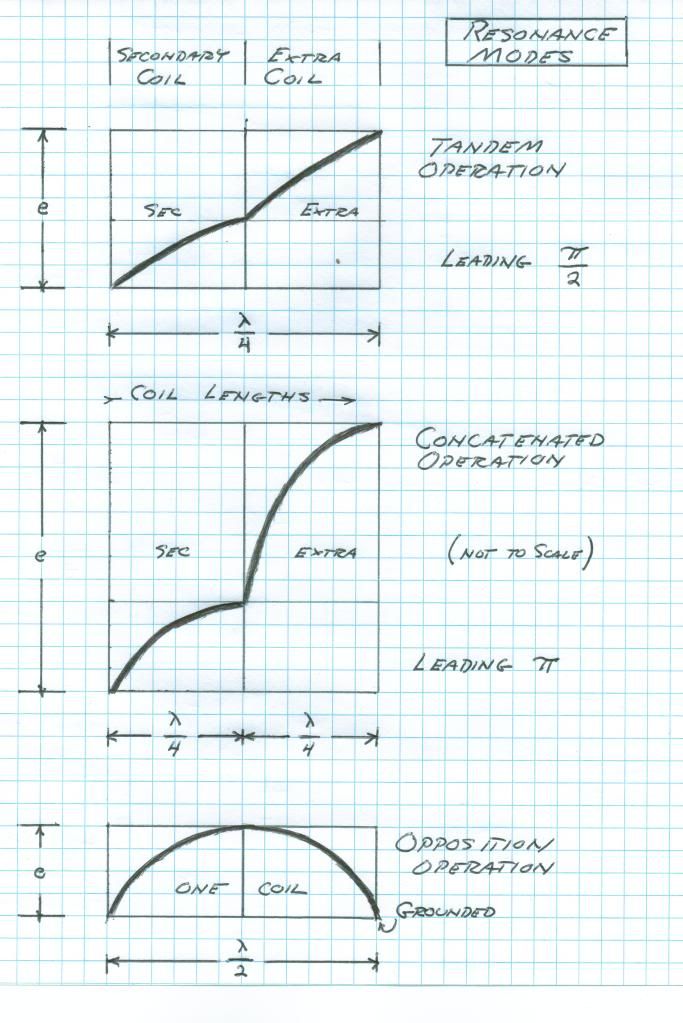
                      • It's not a normal antenna. It has a normal quarter wave voltage and current distribution LIKE an antenna.

                        What has been measured happens to match what Eric said it should be, and was provided in the context of and with all the other relevant data. You have shown what yours is, but frankly I'm not convinced for a number of reasons.

                        You have still not said what the voltage distribution on your coil is, nor the intended design frequency, nor the conductor length or anything else. Others have measured the same thing as I have shown, so you are the odd one out with your measurements, which leads one to suspect that something must be wrong.

                        And the fact still remains that the probe you are using to measure the coil is too close so is having an effect on the coil and therefore the measurements, as well as the additional capacitance terminal tube which isn't supposed to be a part of the design either. Until these are addressed and the coil is reverted back to default then it's no use telling me that I've built my coils wrong.
                        http://www.teslascientific.com/

                        "Knowledge is cosmic. It does not evolve or unfold in man. Man unfolds to an awareness of it. He gradually discovers it." - Walter Russell

                        "Once men died for Truth, but now Truth dies at the hands of men." - Manly P. Hall

                        Comment


                        • If you would have a memory you would know that all this has been calculated by you about a year ago. This coil is not new. And if you are happy with your coil behaviour that is ok with me I just state my opinion and facts.

                          The study of the backwave is very more interesting than the study of a hertzian wave. It can be used to cloak and it is done se this article.
                          http://arxiv.org/pdf/0709.0363.pdf

                          I have no intention to say you are no the self proclaimed expert. Be it, I just go my own way.

                          Comment


                          • This article is interesting and solves the problems Eric started to solve.

                            http://cdn.intechopen.com/pdfs-wm/9987.pdf

                            You see both the transversal and longitudional network called right handed and left handed network.

                            This is an energy spectre. The right handed part is the normal hertzian part. The left handed resonance is the longitudional part.


                            This is about making materials behave longitudional to light and producing a negative refraction index that can be used to cloak. Now what would they have tried with Tesla coils on a marine ship during the Philadelphia experiment? Perhaps send backwaves to incoming radar?

                            Comment


                            • Originally posted by orgonaut314 View Post
                              If you would have a memory you would know that all this has been calculated by you about a year ago. This coil is not new. And if you are happy with your coil behaviour that is ok with me I just state my opinion and facts.

                              The study of the backwave is very more interesting than the study of a hertzian wave. It can be used to cloak and it is done se this article.
                              http://arxiv.org/pdf/0709.0363.pdf

                              I have no intention to say you are no the self proclaimed expert. Be it, I just go my own way.
                              No I don't remember calculations I made a year ago I'm afraid.

                              Revert to default configuration and then see what measurements you get. The whole point of establishing a standard test configuration is so that data becomes universally useful.

                              Have you measured the voltage gradient or is there some other reason you're avoiding answering that question?
                              http://www.teslascientific.com/

                              "Knowledge is cosmic. It does not evolve or unfold in man. Man unfolds to an awareness of it. He gradually discovers it." - Walter Russell

                              "Once men died for Truth, but now Truth dies at the hands of men." - Manly P. Hall

                              Comment


                              • And here the mathematics that show that the longitudional network has as a solution a wave that travels backward and it has negative mu and epsilon. So it refracts light in an unusual way

                                http://xlab.me.berkeley.edu/MURI/Kickoff/Jan25/Itoh.pdf

                                Comment

                                Working...
                                X