Announcement

Collapse
No announcement yet.

Eric Dollard

Collapse
This is a sticky topic.
X
X
 
  • Filter
  • Time
  • Show
Clear All
new posts

  • Recent progress

    Hi all,

    I started trying to investigate what was causing the dark spots on the fluorescent tube. I haven't reached any conclusions as of yet, but have concluded that more measurements need to be taken, specifically the fields going on in between the coils.

    What I am particularly interested in is the mechanism of how the illuminated plasma propogates down the fluorescent tube if only one end of the tube is in a strong enough field to start ionizing the gas. I don't have much of a chemistry background here so I can't really comment on the mechanism of plasma ionization but I assume the dielectric field is imparting some of its energy to the electrons in the gas somehow. Then when some of the gas is ionized, the excited electrons start to excite other electrons to spread the plasma to areas where the e field wasn't strong enough to ionize the plasma on its own. What baffles me is how this propagation can be halted in certain interference spots. Maybe the dielectric field is polarized in the dark areas in such a manner it repels approaching electrons?

    After doing some research I'm pretty sure we're dealing strictly with near field radiation here, considering the short distance of coils (~2 meters) vs wavelength (~ 160 meters). By near field radiation I mean dielectric and magnetic fields that are still coupled to their metallic source, not existing freely in space. Far field radiation implies electromagnetic waves propagating on their own, uncoupled from their source. Apparently there is more than just near and far field radiation, there is also a middle transitional field called the Fresnel region, that is a combination of both near and far field radiation. There are specific distance delineations between the 3 regions related to the wavelength of the RF emitted. Which region you are in mainly affects the phase between the magnetic and dielectric fields. With near field being purely reactive (90 degree phase relationship) and the electric and magnetic fields being in phase (in time) in the far field. The cutoff of strictly near field radiations is listed as about lambda over 6, or around 25 meters. I think its pretty safe to say that we are dealing with strictly near field behavior (since the coils are only 2-3 meters apart max.

    Since it is near field radiation, what determines field strength at a given point? Is it the compilation of both magnetic and dielectric strength, or does it refer to the dominant field, or is it taken as one of the fields? I don't know the answer. With far field radiation the magnitude of the dielectric and magnetic fields should be equal. What I would like to do is map out both the magnetic and dielectric fields surrounding the coils. I intend to get to the bottom of this!

    I'm currently working on creating a better platform for the coils that includes a metric for the coil distance measurements as well as an X-Y grid for field strength mapping. I want to be able to map out the 3D dielectric and magnetic fields in space for a given coil configuration. I'm trying to think of the best way to accomplish this. So far my search for near field probes has yielded some incredibly expensive pieces of equipment, far outside my price range. I'm looking for some homebuilt options. It looks like a langmuir probe to detect the dielectric field would be pretty easy to build. There seem to be multiple options when building a magnetic field detector:
    - single turn loop to measure the field in one direction:

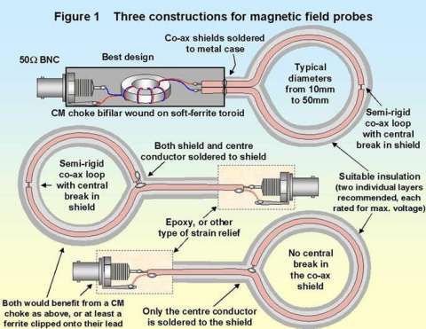
    -single loop but with mulitple turns
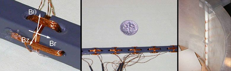
    -3 perpendicular coils to measure the magnetic field in all 3 directions:


    One of the things that comes to mind is are we dealing with static or dynamic fields? Clearly dynamic fields are being radiated from the antennas but do their interference patterns form a standing wave/field? If so, that will change how the fields need to be measured. Another thing I've thought of is it possible to measure the phase of the measured field? i.e. what antenna that particular field was radiated from?
    Any hints in measurement techniques would be greatly welcomed.

    Also I think it would be really cool to measure the radiated fields of both sets of coils independently, and then measure them together and see if the superposition of results match. Interesting to see would be the field strength near the dark region of the bulb. Is it a strong electric or magnetic field or is it null? It could bring more light to whats going on there.
    Please help support my indiegogo campaign: Cosmic Induction Generator

    Comment


    • dR-Green, I would suggest you switch your axises on your graph, as the power clearly depends on the distance, and therefore, the distance ought to be on the x-axis, whereas the power should be on the y-axis.

      Comment


      • EV Gray Forum

        Aaron,
        Could you please direct me to the EV Gray Forum you were referring to.
        Thanks.
        Found the Meyer's VIC site and will read up on that.

        Anybody using Ferrites to form a closed loop in an induction circuit needs to have an air gap of at least 1mm at one end in order to reduce the permeability.
        See here on Page 6:

        Coils and transformers

        Smokey
        Last edited by David G Dawson; 03-26-2014, 05:34 AM. Reason: Page #

        Comment


        • Originally posted by David G Dawson View Post
          Aaron,

          Anybody using Ferrites to form a closed loop in an induction circuit needs to have an air gap of at least 1mm at one end in order to reduce the permeability.
          See here on Page 6:

          Coils and transformers

          Smokey
          Smokey,
          If you were referring to the ferrite in the field probe, its a common mode choke so it only filters out the noise and doesn't act as an inductor/impedance to the signal. The wires are wrapped in opposite directions so their flux cancels.
          Please help support my indiegogo campaign: Cosmic Induction Generator

          Comment


          • Ed Gray thread

            Originally posted by David G Dawson View Post
            Aaron,
            Could you please direct me to the EV Gray Forum you were referring to.
            Thanks.
            http://www.energeticforum.com/renewa...plication.html
            Sincerely,
            Aaron Murakami

            Books & Videos https://emediapress.com
            Conference http://energyscienceconference.com
            RPX & MWO http://vril.io

            Comment


            • Originally posted by jpolakow View Post
              Dr Green,

              Excellent work! I am impressed!I think you are definitely the forerunner in investigating Telluric transmission of power! Good job!

              One question for you- what is the coil configuration you are using when you photographed the dark spot on the bulb? Were you using two coil sets or just one? It would be particularly interesting if one coil set can produce that interference pattern.

              Oh also check this out- I was referred to this site and should pass it on to you-
              David Knight is able to show standing waves in a (non-phosphor coated) plasma tube:
              Inductor self-resonance experiments

              John
              Thank you John. Those are some very nice images on that page! I like the tubes he's using.

              I was using just one coil set. I don't have enough voltage to be able to light tubes with the secondary alone (without extra coil), but I assume you should be able to get the same dark spot with just the secondary on your setup (unless it specifically has something to do with the extra coil). I'm not sure if it would still do the same with two coil sets. It would be interesting if either both dark bands are present at the same time producing a "cross", or if it rotates by 90 degrees depending whether one or two coil sets are used.

              Another thing I didn't mention is "travelling" patterns using an 18W tube, but so far I've had to hold the tube in my hand and things seemed to be moving to or from my hands, so I'd like to dangle it from a stick with a piece of string and see if the same still happens. This is again with the tube parallel to the coil winding so effectively from left to right, not from top to bottom of the coil.
              http://www.teslascientific.com/

              "Knowledge is cosmic. It does not evolve or unfold in man. Man unfolds to an awareness of it. He gradually discovers it." - Walter Russell

              "Once men died for Truth, but now Truth dies at the hands of men." - Manly P. Hall

              Comment


              • Originally posted by Tenaus View Post
                dR-Green, I would suggest you switch your axises on your graph, as the power clearly depends on the distance, and therefore, the distance ought to be on the x-axis, whereas the power should be on the y-axis.
                http://www.teslascientific.com/

                "Knowledge is cosmic. It does not evolve or unfold in man. Man unfolds to an awareness of it. He gradually discovers it." - Walter Russell

                "Once men died for Truth, but now Truth dies at the hands of men." - Manly P. Hall

                Comment


                • Originally posted by dR-Green View Post
                  Thank you John. Those are some very nice images on that page! I like the tubes he's using.

                  I was using just one coil set. I don't have enough voltage to be able to light tubes with the secondary alone (without extra coil), but I assume you should be able to get the same dark spot with just the secondary on your setup (unless it specifically has something to do with the extra coil). I'm not sure if it would still do the same with two coil sets. It would be interesting if either both dark bands are present at the same time producing a "cross", or if it rotates by 90 degrees depending whether one or two coil sets are used.

                  Another thing I didn't mention is "travelling" patterns using an 18W tube, but so far I've had to hold the tube in my hand and things seemed to be moving to or from my hands, so I'd like to dangle it from a stick with a piece of string and see if the same still happens. This is again with the tube parallel to the coil winding so effectively from left to right, not from top to bottom of the coil.
                  Yes I have been able to get the dark band with just one coil set. Also I I'm able to do it with just the secondaries (I dont have any extra coils yet).

                  Yea I was also getting those weird "travelling" striations of thin dark bands. I'm not sure what they are.

                  One thing that confuses me is that to get a dark band, it would seem to imply the dark spot is at a nodal point of the dielectric field (i.e. a zero value). For the secondary at least, the peak value should be at the end of the secondary. Then the minimum value or nodal point should be 1/4 wavelength away in space right? For the low frequencies we are using this is a significant distance so I'm not sure why the dark band appears there.

                  I'm currently getting ready to build a dielectric field probe to get to the bottom of this.

                  Any ideas?
                  Please help support my indiegogo campaign: Cosmic Induction Generator

                  Comment


                  • Originally posted by jpolakow View Post
                    These were the two hardest images to come by. This is using a 4 ft long fluorescent tube. These things light up much easier than the smaller tube, so it was harder to get completely dark spots. It was extremely difficult to find two interference patterns, let alone photograph them at the same time. These are the two most impressive pictures in my opinion, even if the interference patterns weren't as pronounced as some of the others.


                    I did some hard thinking after these tests and something immediately came to mind. If I stuck just one end of the fluorescent lamp near the coils, the entire tube would light up. That is, if one end of the tube was receiving enough energy to ionize the gas inside, the plasma would propagate down the entire tube. Here's a couple pics demonstrating this with a 4 foot fluorescent tube, to really show the plasma propagates down the tube:


                    So all it took was part of the fluorescent tube to be receiving field energy and it would be spread through the ionized molecules, and light up the whole tube even if the other end of the tube wasn't receiving any field energy. So the plasma inside the tube tends to spread, regardless of whether or not a field is present. Now this is what seems interesting to me, and please correct me if I am mistaken because I'm not very knowledgeable about plasma but:

                    This tells me one of two things is happening in the "dark spots"
                    1. The interference pattern is actively sucking energy away from the tube in this area to prevent a plasma from forming.
                    or
                    2. The interference pattern somehow prevents energy from the "lit" plasma being transferred to the unlit regions of the tube.
                    Any comments or criticism are welcome!
                    I was getting these dark spots in the fluros's some time ago, i could get them to travel along the tube as small cylinder type dark spots, i could get them to go from one end to the other or from both ends to the middle or from the middle to both ends. I'm having trouble finding the video showing the travelling dark spots, i'll post it when I do.

                    I discovered I could do it back in 2011.

                    This clip at about 4:45 I show one.
                    https://www.youtube.com/watch?v=S-XMmlynCLQ

                    This clip has all kinds of freaky patterns and some dark spot action towards the end.
                    https://www.youtube.com/watch?v=Gr9JX_sIP2I

                    Another one.
                    https://www.youtube.com/watch?v=61psmS8WKTU

                    Cheers

                    P.S. Here's one of the travelling dark spot, it could be done almost any time the coils were resonant. If the fluro is held in different ways the spots move in different ways. I'm sure I have a better video but they are not labeled well.

                    https://www.youtube.com/watch?v=FLuaJHGc-jc

                    ..
                    Last edited by Farmhand; 03-29-2014, 05:39 AM.

                    Comment


                    • A review of a few experiments early 1900 by lecturer Robert Richardson in 1981 Cornell.
                      He reminds us of some good perspective of current flow, detection methods, nodes, and other ideas :
                      PHYS Electromagnetic Waves - YouTube

                      Some scientist made discoveries while electrical storms brewed. Journals kept during episodes of brilliant genius refer to a magnetometer kept on the desk that went wild during an approaching electrical storm. A magnetometers can be as simple as an amplified or modified (DIY ) Gauss meter. I think the relationship is the scientist awareness of the natural demonstration that is from the giant magnetic sphere earth opens the broader perspective that the experiments are not that crazy and the model can and should be improved.
                      Last edited by mikrovolt; 03-29-2014, 10:09 PM.

                      Comment


                      • Tesla published a little bit about nodes.
                        "The True Wireless" by Nikola Tesla
                        see Figure 6
                        Tesla said you can move the node by using a capacitance? at one end.

                        Consider now the effect of such a conductor of vast dimensions on a circuit exciting it. The upper diagram of Fig. 6 illustrates a familiar oscillating system comprising a straight rod of self-inductance 2L with small terminal capacities cc and a node in the center. In the lower diagram of the figure a large capacity C is attached to the rod at one end with the result of shifting the node to the right, thru a distance corresponding to self-inductance X. As both parts of the system on either side of the node vibrate at the same rate, we have evidently, (L+X)c = (L-X)C from which X = L(C-c/C+c). When the capacity C becomes commensurate to that of the earth, X approximates L, in other words, the node is close to the ground connection. The exact determination of its position is very important in the calculation of certain terrestrial electrical and geodetic data and I have devised special means with this purpose in view.

                        Comment


                        • The strange thing about these nodes seems to me that the secondary coil has a length of prox 20 meter or more and that is a quarter wave resonance so the full wave is over 80 meter.

                          Comment


                          • What makes me think twice about the travelling dark spots in the fluro is that
                            they resemble the cables with bands/spots in the Dendera carvings in Egypt.

                            See attachment, in the actual carving the dark spots are still there but are more
                            difficult to see.

                            Considering I got those effects with 12 volt powered coils and less than 10 Watts.

                            Cheers
                            Attached Files

                            Comment


                            • Gold suspension?

                              While in a bottle shop recently I noticed Vodka bottles that had some gold leaf suspended inside the bottle. The leaf seems fairly equally spread and even if you shake the bottle the leaf remains in its position. It doesn’t float to the top or sink to the bottom. The combination of the weight the gold leaf to surface area, the viscosity of the vodka and perhaps an electrical charge also put the Gold leaf forms a nice macro colloidal-like suspension.

                              Just throwing the idea out-there: - Could such a suspension be a dielectric field indicator? As the gold leaf suspension if brought within the field of the CIG, would the particles align themselves with the dielectric field? Perhaps other materials might form a suspension in a more suitable liquid such as mineral oil, together with gold leaf, aluminium foil, or other similar suspension material.

                              If the (gold) leaf suspension worked and the leaf took the form of the dielectric field, similar to the way iron fillings work with a magnet, this could help map what’s happening within the field of the CIG?
                              One might have an aquarium sized suspension to place in between the coils?

                              It may not even work? The particles might glow white hot? Maybe too hard & messy to be of any practical use?

                              Sputins.
                              "Doesn't matter how many times you kick the coyote in the head, it's still gonna eat chickens". - EPD

                              Comment


                              • Originally posted by Sputins View Post
                                While in a bottle shop recently I noticed Vodka bottles that had some gold leaf suspended inside the bottle. The leaf seems fairly equally spread and even if you shake the bottle the leaf remains in its position. It doesn’t float to the top or sink to the bottom. The combination of the weight the gold leaf to surface area, the viscosity of the vodka and perhaps an electrical charge also put the Gold leaf forms a nice macro colloidal-like suspension.

                                Just throwing the idea out-there: - Could such a suspension be a dielectric field indicator? As the gold leaf suspension if brought within the field of the CIG, would the particles align themselves with the dielectric field? Perhaps other materials might form a suspension in a more suitable liquid such as mineral oil, together with gold leaf, aluminium foil, or other similar suspension material.

                                If the (gold) leaf suspension worked and the leaf took the form of the dielectric field, similar to the way iron fillings work with a magnet, this could help map what’s happening within the field of the CIG?
                                One might have an aquarium sized suspension to place in between the coils?

                                It may not even work? The particles might glow white hot? Maybe too hard & messy to be of any practical use?

                                Sputins.
                                Thats a good idea Sputins. I briefly looked into this when thinking about how to map out the field behavior. One problem I forsee is that the field lines from a magnet are static, whereas with the CIG they oscillate at around 2 Mc, constantly changing. That being said perhaps the field lines follow the same "path" so the suspended particles could stay in relatively the same place. Perhaps a smaller version could be tried first in a jar to see the results.
                                Please help support my indiegogo campaign: Cosmic Induction Generator

                                Comment

                                Working...
                                X