Announcement

Collapse
No announcement yet.

Eric Dollard

Collapse
This is a sticky topic.
X
X
 
  • Filter
  • Time
  • Show
Clear All
new posts

  • The coils and setup are excellent work the equipment is relative at this point.
    I was hoping you would hit 2075 Kc in the middle of the graph when capacitor is 50%.
    A Spec Analyzer may show what is going on when the air variable capacitor is between 60 and 90 degrees.
    A goal of 2050 to 2100 Kc for the entire sweep would be great goal. I believe it is a successful build. You hit in the ball park.
    great job!
    Last edited by mikrovolt; 02-27-2014, 04:41 AM.

    Comment


    • JP, the coils look awesome & it’s been great to see your results so far!

      Thanks for explaining the connection or phasing concerning the primary coils. In other words the two primary coils should be wound the same direction but the Secondary coils are wound it the opposite direction to each other.

      It appears that you are driving the secondary coils at full wavelength, not the quarter wave Ro as such. Is this so? Or are you indeed driving at the quarter wavelength? That is one of the differences between myself and dr Green at the moment. Doc Green has been running a quarter wave Ro while I’m using a full wavelength Ro on the primary tank. What are your thoughts / comments on that? Tesla coils are traditionally driven with quarter wavelength but may not necessarily be so.

      I have found with testing my coils (although I only have one half complete at the moment) and as such I omit powering up the main transmitter mostly, although I still leave it connected. Using a very low power driver I connect it directly to the base of the secondary (telluric output, or where your two are connected). Now a frequency sweep can be done while watching the meter peak (mine is a loop-stick uA meter with a variable R pot). I found that when doing this the variable capacitor on the tank circuit can be adjusted ‘on the fly’ which affects the peak on the loop-stick meter and the optimum peak, with the optimum position for the tank circuit capacitor can be found this way. Using that setting I then use the same low power driver to now power the up the transmitter (input) and generally it’s still spot on the optimum setting. Now even with low power on the transmitter the loop-stick meter pegs. Now the variable R-pot on the loop-stick can be adjusted to bring the meter back into range. Turning up the power on the transmitter, I have to take the L-S meter far away so it no longer pegs. I’m making some other non-contact test meters to detect the voltage which should help me further.

      However as your graphs show for any given frequency there is an optimum tank circuit capacitance setting, or reversed for any given tank capacitor setting there is an optimum frequency. However there is one which will have the optimum Q or sharpness. Looks like from you graph the one with the 60 degree shaft setting gave the sharpest graph with the peak at 1.96Mc.

      As you say, there are many combinations of parameters to yield the maximum power output. It’s part of the fun with experimenting! - Wonderful work Sir.

      Sputins.
      "Doesn't matter how many times you kick the coyote in the head, it's still gonna eat chickens". - EPD

      Comment


      • Originally posted by jpolakow View Post
        Any comments or criticism is welcome!
        Excellent work John. Thanks for the diagrams and info on the primary and phasing.
        http://www.teslascientific.com/

        "Knowledge is cosmic. It does not evolve or unfold in man. Man unfolds to an awareness of it. He gradually discovers it." - Walter Russell

        "Once men died for Truth, but now Truth dies at the hands of men." - Manly P. Hall

        Comment


        • Made a new video utilising the receiving coil. On a related note, some people in the past have objected to the idea/reality that the same system was/is to be used to transmit/receive power and "radio" or intelligence with no fundamental changes to the general arrangement, so three applications are demonstrated simultaneously, or four if the light also be considered as heat. There is NO power supply or amplification on the receiving end, the only power available is that received from the transmitter.

          The motor is geared down, the label on it says 12V 2.2W. The speaker is approx 16" diameter 50W and I believe 8 ohms, the bulb is the 28V type mentioned a few pages back, I forget what #

          Tesla Magnifying Transmitter And Receiver- Light, Intelligence And Motive Power - YouTube
          http://www.teslascientific.com/

          "Knowledge is cosmic. It does not evolve or unfold in man. Man unfolds to an awareness of it. He gradually discovers it." - Walter Russell

          "Once men died for Truth, but now Truth dies at the hands of men." - Manly P. Hall

          Comment


          • Hi All!

            Thanks for the information on how to tune and measure the coils. I am still in the driver construction area but I finished my 6sn7 driver and it works.


            However I have a question. I'm running on 3,2MHz and the mu seems to drop to 5. On 300kHz it is something like 10. My question is was this driver suggested to work with 1MHz and am I correct in saying that 3,2MHz is to much for this tube? I have checked all other possible explanations by using metal film resistors and checking my scope probe that is 100MHz etc. I can find nothing wrong but the tube itself. Please someone with experience with RF and tubes give me a clue! Thanks!


            Comment


            • orgonaut314, that looks like a really good assembly for tube experimentation. Scribble the circuit down so we can take a look.

              Comment


              • Originally posted by madhatter View Post
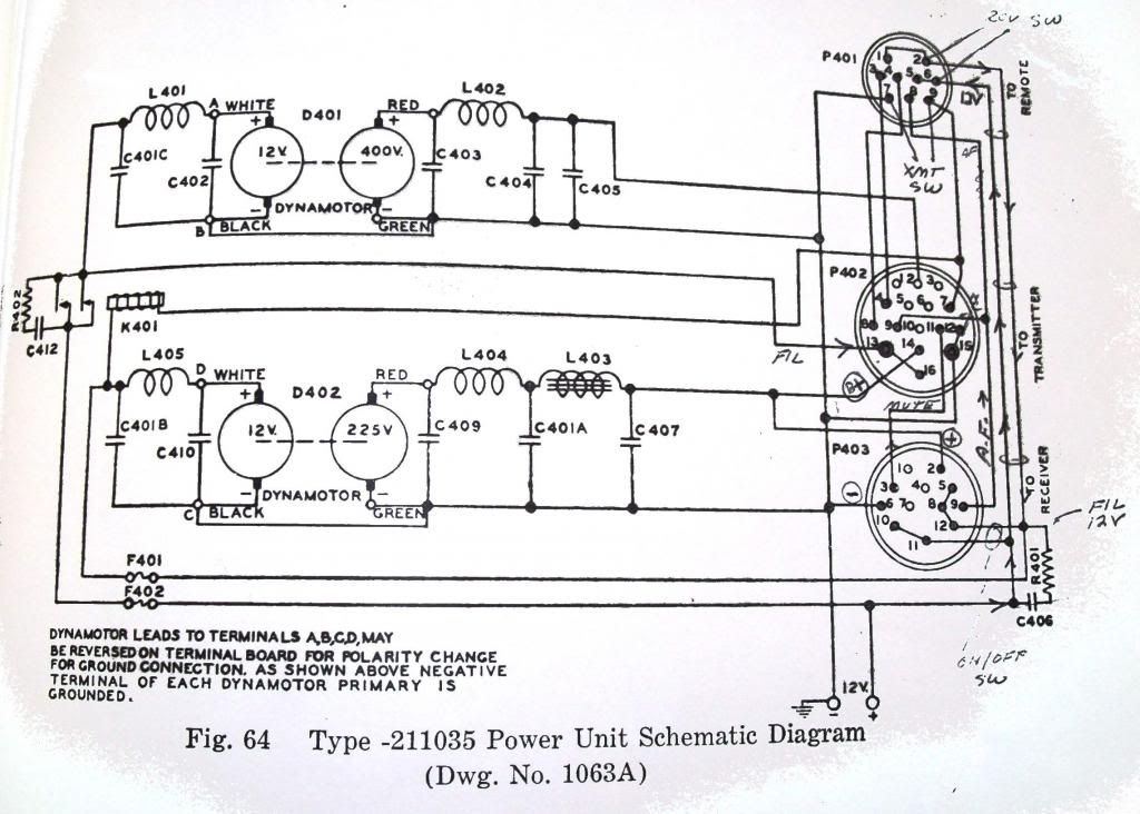
                Thanks, what was used as the PS (power supply) for the TCS 12?
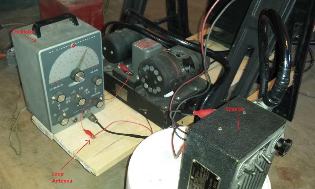
                A dynamotor (dc motor generator) power supply was used, that came with the TCS. It has two dynamotors, one that puts out ~400VDC, and one that puts out ~220 VDC.

                The schematic is below:


                You can see the dynamotor PS next to the Heathkit RF oscillator in this pic:
                Last edited by jpolakow; 02-27-2014, 04:57 PM.
                Please help support my indiegogo campaign: Cosmic Induction Generator

                Comment


                • Originally posted by Sputins View Post
                  JP, the coils look awesome & it’s been great to see your results so far!

                  Thanks for explaining the connection or phasing concerning the primary coils. In other words the two primary coils should be wound the same direction but the Secondary coils are wound it the opposite direction to each other.

                  It appears that you are driving the secondary coils at full wavelength, not the quarter wave Ro as such. Is this so? Or are you indeed driving at the quarter wavelength? That is one of the differences between myself and dr Green at the moment. Doc Green has been running a quarter wave Ro while I’m using a full wavelength Ro on the primary tank. What are your thoughts / comments on that? Tesla coils are traditionally driven with quarter wavelength but may not necessarily be so.

                  I have found with testing my coils (although I only have one half complete at the moment) and as such I omit powering up the main transmitter mostly, although I still leave it connected. Using a very low power driver I connect it directly to the base of the secondary (telluric output, or where your two are connected). Now a frequency sweep can be done while watching the meter peak (mine is a loop-stick uA meter with a variable R pot). I found that when doing this the variable capacitor on the tank circuit can be adjusted ‘on the fly’ which affects the peak on the loop-stick meter and the optimum peak, with the optimum position for the tank circuit capacitor can be found this way. Using that setting I then use the same low power driver to now power the up the transmitter (input) and generally it’s still spot on the optimum setting. Now even with low power on the transmitter the loop-stick meter pegs. Now the variable R-pot on the loop-stick can be adjusted to bring the meter back into range. Turning up the power on the transmitter, I have to take the L-S meter far away so it no longer pegs. I’m making some other non-contact test meters to detect the voltage which should help me further.

                  However as your graphs show for any given frequency there is an optimum tank circuit capacitance setting, or reversed for any given tank capacitor setting there is an optimum frequency. However there is one which will have the optimum Q or sharpness. Looks like from you graph the one with the 60 degree shaft setting gave the sharpest graph with the peak at 1.96Mc.

                  As you say, there are many combinations of parameters to yield the maximum power output. It’s part of the fun with experimenting! - Wonderful work Sir.

                  Sputins.
                  Hi Sputins,

                  Thanks for the comments.

                  Yes you have that right about the coil phasing. The primary direction of winding is arbitrary, but the secondaries MUST be wound in opposite directions. Then the primary connections are adjusted to the proper phasing. Final determination is made by checking with the fluorescent bulb to verify the coils are out of phase.

                  I am indeed driving the secondaries at quarter wavelength. Why did you think I was driving them at full wavelength?
                  Please help support my indiegogo campaign: Cosmic Induction Generator

                  Comment


                  • Originally posted by Geometric_Algebra View Post
                    orgonaut314, that looks like a really good assembly for tube experimentation. Scribble the circuit down so we can take a look.
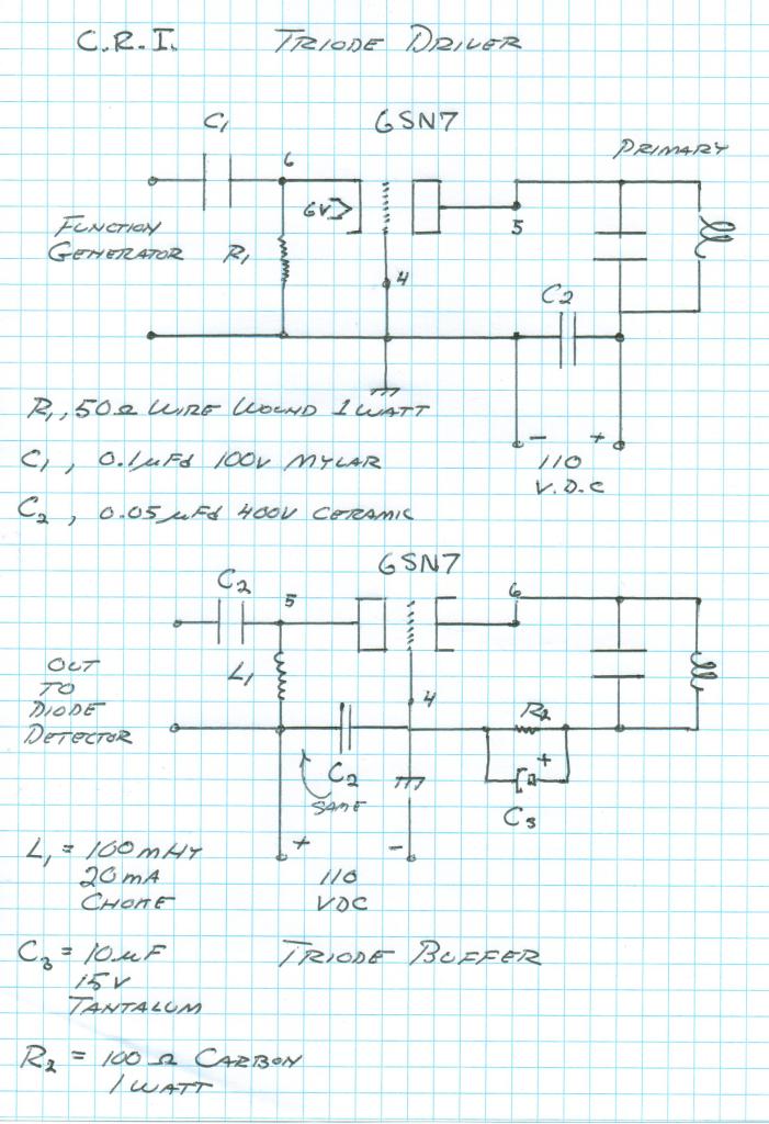
                    Basically Eric's schema but I coupled it out to avoid the dc but without the out coupling cap the mu also dropped to 5 at 3.2MHz.

                    My input is 3,5V from the frequency generator and it has 4Volt dc at the cathode. The anode has 110V dc.

                    Last edited by orgonaut314; 02-27-2014, 08:06 PM.

                    Comment


                    • Originally posted by orgonaut314 View Post
                      Basically Eric's schema but I coupled it out to avoid the dc but without the out coupling cap the mu also dropped to 5 at 3.2MHz.

                      My input is 3,5V from the frequency generator and it has 4Volt dc at the cathode. The anode has 110V dc.

                      Per your schematic the tube is non-functioning. in other words there is no signal on the grid and the cathode R is very small, making for large currents to drain thru it from the plate. What's the goal? I could work up a schematic with values later tonight. it's a simple amp circuit, SE. (single ended)

                      Comment


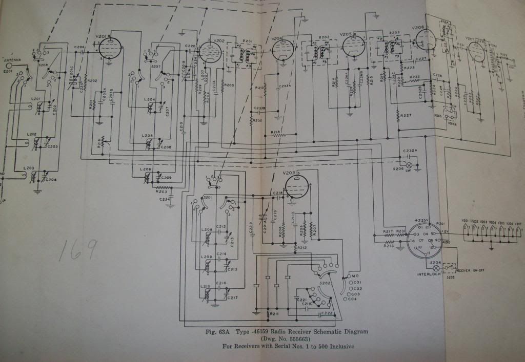
                      • Thanks Jon, I'll give all the data a look over in the next couple days and see what I can find. I'm trying to locate an internal schematic on the receiver, interesting to see what kind of isolation is occurring between it and PS.

                        Comment


                        • Originally posted by madhatter View Post
                          Per your schematic the tube is non-functioning. in other words there is no signal on the grid and the cathode R is very small, making for large currents to drain thru it from the plate. What's the goal? I could work up a schematic with values later tonight. it's a simple amp circuit, SE. (single ended)
                          Hi its a grounded grid. See this Eric drawing:


                          But the reason why my mu is low might be because the probe from my scope seems to be broken at high frequencies. Have to buy a better one.

                          Comment


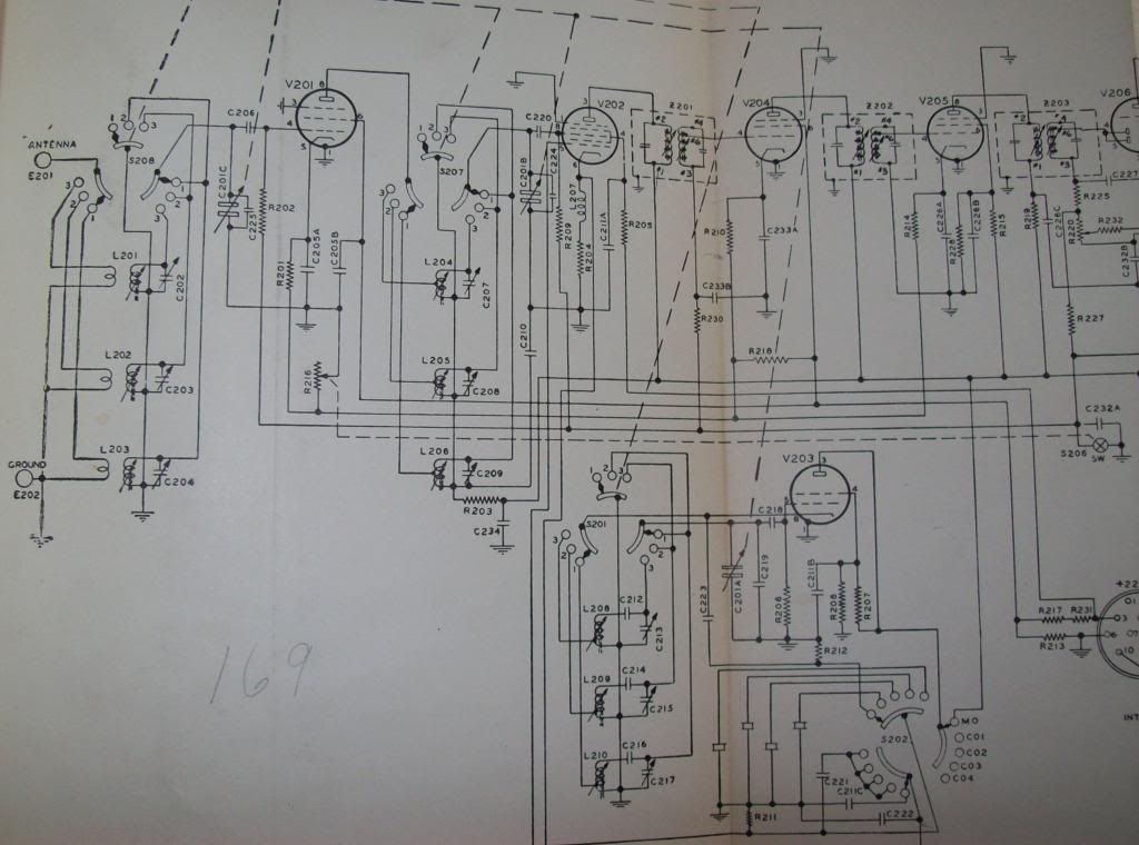
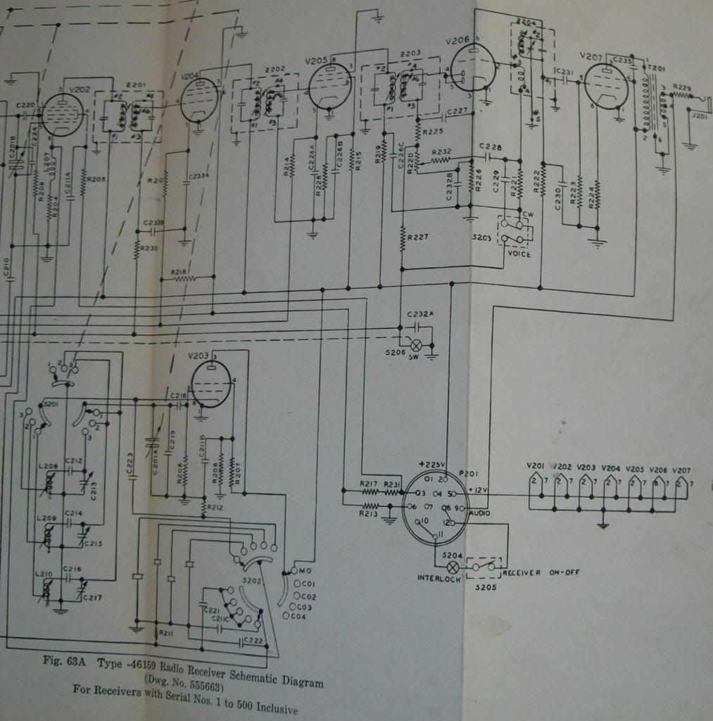
                          • Receiver Schematic

                            Originally posted by madhatter View Post
                            Thanks Jon, I'll give all the data a look over in the next couple days and see what I can find. I'm trying to locate an internal schematic on the receiver, interesting to see what kind of isolation is occurring between it and PS.
                            Hi Madhatter,

                            Here you go:
                            Please help support my indiegogo campaign: Cosmic Induction Generator

                            Comment


                            • Here's a couple better ones:


                              Please help support my indiegogo campaign: Cosmic Induction Generator

                              Comment


                              • Originally posted by orgonaut314 View Post
                                Hi its a grounded grid. See this Eric drawing:


                                But the reason why my mu is low might be because the probe from my scope seems to be broken at high frequencies. Have to buy a better one.
                                thanks hadn't seen this one, it's a grounded grid amp..
                                Grounded Grid Amplifiers

                                Comment

                                Working...
                                X