 Tweet
Tweet
Originally posted by Atlas
View Post
-
Ya I think a point Eric has been making is the fact that current mathematics can`t properly analyze the tesla transformer because it only looks at one half of the picture, ie bipolar as opposed to quadrapolar, perhaps I`m wrong on this? -
I would be honored if you took the time to point out where or what exactly I'm missing.Originally posted by Atlas View Post
I get that Tesla believed in a Pi/2 velocity, he also chalks it up to being like a shadow moving acrost a spherical object, which is in the realm of perspective geometry--a fascinating subject. He never gives a valid scientific answer as to how his wave propagation really worked. He convinced Helmholtz yes, but not Heaviside--who thought Helmholtz' (Tesla inspired) longitudinal model was all but useful. Can you explain how Tesla's longitudinal waves work?
In general, outside of Coulomb oscillations, longitudinal wave propagation through vacuum is considered as impossible. Could it be possible for longitudinal waves to propagate in some "other space?" Probably. But not vacuum in our 4-space--matter is required for longitudinal waves to exist, which isn't true for EM waves.
Something of interest in regard to longitudinal waves, is that they are known to exist in plasma, with special reference to odd conditions that have no Poyntine flux (the matter moves the energy, instead of photons). The conditions for this mode of oscillation might be possible in coils, however a free-space longitudinal wave doesn't exist. I.e. your not going to bounce "scalar waves" off the moon and detect them back here on earth.
Personally, I think people are better off experimenting with plasma tubes than 1940s era coils. Don't get me wrong, coils are fun, but more is known about longitudinal waves in plasma than in RF coils.Last edited by upgradd; 02-25-2014, 02:41 AM.Comment
-
Thanks. I would say that the soil in a bucket behaves very similar if not exactly the same as the earth itself in some respects, the main difference being that the earth "absorbs" the energy a lot more effectively, but other than the amount of power required for that reason, the most notable effects are practically identical. A few minutes ago, using the same amount of power that was used in the video I lit the smallest lamp that's in the video VERY dimly (through holding it) on the earth terminal in the garden with the transmitter connected to it. But as noted before, when transmitting signals with even less power than this (and the old coils) an audible signal is quite easily picked up with no physical connection either through a tuned receiver or a simple AV plug with crystal earpiece up to possibly a 6 metre diameter area surrounding the transmitter earth terminal, and up to a certain distance an AV plug can be plugged into the earth to power LEDs, so no doubt as much as my body capacitance was allowing the filament to light very dimly, the whole thing was also effectively shorted out through me standing on the ground right next to the earth terminal. But otherwise the bucket allows for experimenting with similar things with less power. You should be able to get reasonable light from the earth terminal with small bulbs at least with your (more powerful) amp, that should be good.Originally posted by Sputins View Post
This film isn't so bad, I think the bulbs in a field scene is what inspired me to try the soil in a bucket to begin with.
The Secret Of Nikola Tesla-movie - YouTubehttp://www.teslascientific.com/
"Knowledge is cosmic. It does not evolve or unfold in man. Man unfolds to an awareness of it. He gradually discovers it." - Walter Russell
"Once men died for Truth, but now Truth dies at the hands of men." - Manly P. HallComment
-
Here are some ramblings, feedback a simple minded approach or reproach.
The solar system is a pseudo-circuit. An L-wave can travel over a laminated resonating coil from primary to secondary thus a one wire is a subset.
Earth's Magnetic Shield
The earth is an oblate spheroid. A gravity wave going inside the atmosphere can exert force pulling outward along the hemisphere to make the oceans rise. A more intense gravity wave can interact with the earth producing shockwaves.
PreyFiles.com - Picture of The Day
As a rough model let the earth be the baked potato in the picture and the fingers be the flux of solar flair a vast ocean of solar wind exerting force inward so as to squish the potato inward.
http://startcooking.com/public/images/IMGP2628.JPG
Fortunately the inward and outward are absorbed and allow the earth to stay intact. The the flux lines both inward and outward that emanate from the earth are making atmospheric sounds as a bell being struck. evidence of solar pseudo-circuit. CONNECTED normally on but sometimes disconnected then reconnected to our a big capacitor. The visual here like distributor contacts opening briefly.
I have been trying to find an inexpensive model to examine ?
The latest Slayer coils are inexpensive and very efficient design that works and is available off shelf. ( Would this work ? ) I think it is interesting. I think his work also deserves credit is less shocking and lends itself well to proof and refinement of our math, also is another avenue to get repeatability in quantitative analysis out there that people have access to. The Dollard program is full scale and we should be honing our skills as the project moves forward.
Simulation of Naudin replication of Dollard transmission line has been awaiting subroutines awhile. used this to develope a transistor oscillator uses nichrome output coil to wave shape pulse to an asymptotic wave.Last edited by mikrovolt; 02-27-2014, 03:36 PM.Comment
-
Only thing I can advise is to watch Eric's presentations, to read the material he recommends and to perhaps do the experiments for one's self.Originally posted by upgradd View PostComment
-
Eric Dollard Answers Facebook Questions
Eric Dollard answers latest questions asked on his Facebook page:
Eric Dollard - Answers Facebook Questions - 2014-02-23 - YouTubeSincerely,
Aaron Murakami
Books & Videos https://emediapress.com
Conference http://energyscienceconference.com
RPX & MWO http://vril.ioComment
-
I watched most of the video, one part stood out.
That is, Plancks Constant as defined per a physicist definition:
Unless I missed something major in school Planck's constant is a proportionality constant, the energy of a single photon in relation to the frequency of it's electromagnetic radiation.Originally posted by Eric
The energy E contained in a photon, which represents the smallest possible 'packet' of energy in an electromagnetic wave, is directly proportional to the frequency f according to the following equation:
E = hf
If E is given in joules and f is given in hertz (the unit measure of frequency), then:
E = (6.626176 x 10⁻³⁴) f
and conversely:
f = E / (6.626176 x 10⁻³⁴)
in other words it's the smallest amount of unit energy. Now I'll be the first to say I don't like the use of term 'particle' it implies a physical 'chunk' of matter, nothing could be further from the truth. in reality it's a field of energy, in this case the planck is the smallest 'field' unit of energy. the photoelectric effect can be used to measure this.
orbitals are energy levels not physical orbits, a lot of the early terms we are stuck with, it was the natural progression from 'mechanics' but it also trips up a lot of people and esp the laymen as it conjures up images of planets etc.. also didn't help that many diagrams also utilize such things too.
it also has many uses in optical communications via the photoelectric effect and the ability to measure and control the energy levels with photons.
I'll ask this, if you don't like Planck's constant, what of the photon?Comment
-
Coil Tests
During my most recent trip to the lab, I was able to meet with Eric and do some testing of the coils I built. The design goal of these coils was to be used in a "CIG" configuration, that is they were to be wired in push-pull, ungrounded, so they wouldn't transmit. This way no RF would be transmitted out which could interefere with or damage sensitive electronics. That being said, the coils were still built in a modular fashion, so their configuration could be easily changed to a transmit or receive type of situation. The objective of this trip to the lab was to do some preliminary testing of the coils, and to see how their actual behavior matched up with their designed behavior.
Design Targets
These coils were designed to be resonant on 1.8 Megacycles. This frequency was chosen because it is a ham band (160 meters), and also because it's the 100th harmonic of the Alexanderson system. The design of any Tesla coil system begins with the secondary. All of the formulas for the coil calculations have been given previously by Eric Dollard, so I won't repeat them here. The secondary height, width, and turns spacing were calculated. Next to be calculated was the primary. Normally a 1 or 2 turn primary would be used in a Tesla style system. However even a 2 turn primary yields a very small inductive reactance and thus converesely a large capacitor would be needed to resonate with it. In my case, with the rather low frequency of 1.8 Mc, this would have necessitated an extremely large tank capacitor to match the primary. So initially we decided on a 5 turn primary, but later we settled on 3.
Construction
Because 3 turns were used for the primary, it would have been difficult to build the primary conductor from copper sheet. So copper tubing was chosen instead. Because the skin effect is reasonably low at 1.8 Mc, it was decided the conductor volume of the primary should match the secondary. If the frequency had been much higher, then the skin effect would have a larger impact, and it would have made sense instead to have the surface area of the primary match the surface area secondary.
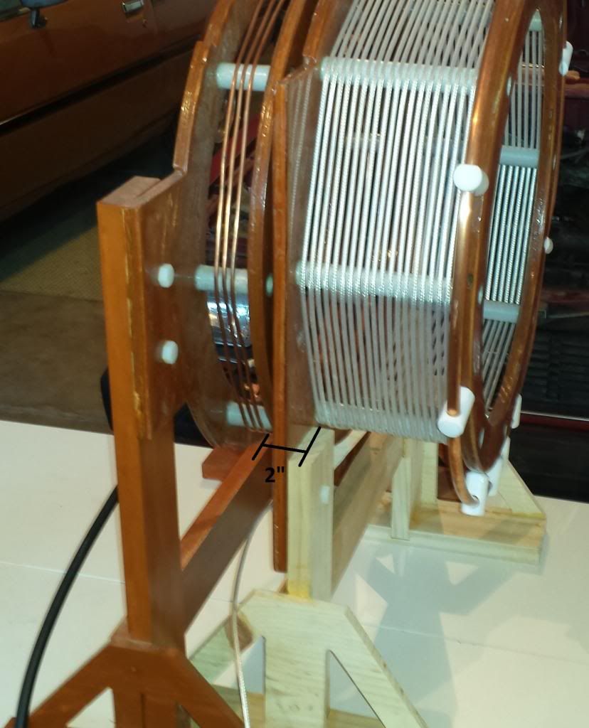
Because the coils would be operated at high voltages, fiberglass tubes were used to construct the coil forms. Notches were placed in the tubes to hold the conductors. The coil form base plates were cut out of plywood, baked, then covered with multiple coats of epoxy to form an insulation barrier. On the secondary side, the windings were made with RG 180 coax. The outer shielding of the coax was used as the conductor, the center conductor of the coax is left unused. The secondary capacitance is formed by a piece of copper tube. Because the secondary will see very high voltages, I machined some teflon spacers to hold the copper tube.
The direction of the windings around the coils plays an important role. For CIG operation, the goal is to have two opposing and opposite dielectric fields radiated from each secondary, to get maximum dielectric field intensity at the center of the two secondaries. For the fields to be opposite directionally, the coils have to be wound opposite. So from the same point of view one secondary will be wound clockwise, and the other will be wound counterclockwise. Then the primaries that drive each secondary were wound in the same direction as the secondary they were driving. Later this proved to be a mistake and we had to reverse a connection on one primary, but the direction of the coil windings we used were:
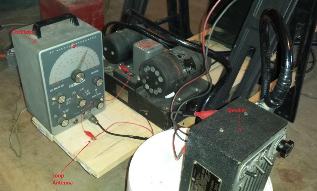
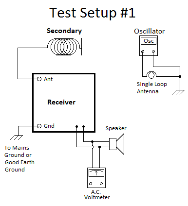
First Test: Resonant Frequency of Secondary
The design frequency of the secondary was 1.8 Mc. Now it was time to test out what the actual resonant frequency was. To perform this test a test oscillator was connected to a small antenna, and the secondary then received the signal. Data was taken as to the relative receive strength of the signal across various frequencies. The test oscillator we used was a Heathkit vacuum tube RF oscillator. The receiver we used was a WWII Navy TCS-12 receiver. The receiver outputs its signal to a speaker, not very useful for data measurement purposes. So we connected an AC voltmeter across the speaker terminals to get precise data points. A note on the data points: the receiver implements AGC, or automatic gain control. This feature tries to keep the audio level stable, not making large changes with varying strength of signals. As a result the data seen can't be viewed as a linear representation of the receive strength. Instead, the data is a logarithmic (or dB) display of the receive strength at different frequencies.

 Last edited by jpolakow; 02-26-2014, 03:23 AM.Please help support my indiegogo campaign: Cosmic Induction Generator
Comment
-
Field Strength Testing
Second Test: Field Strength at Various Frequencies
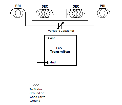
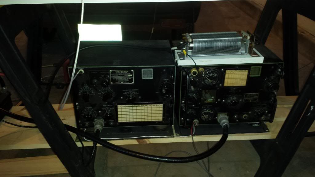
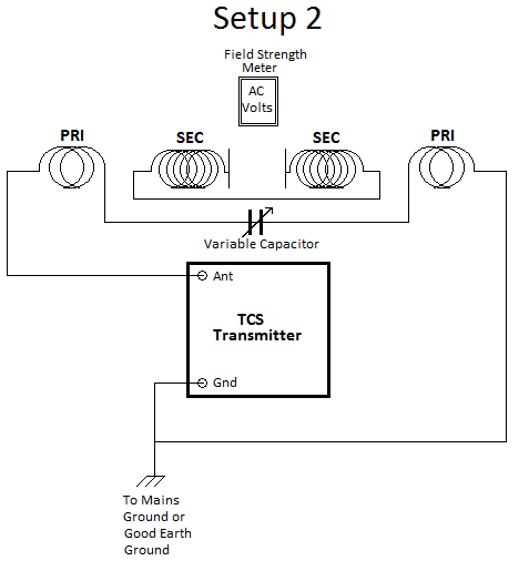
The second round of tests was much more comprehensive. The objective was to see at which frequency the coils gave the strongest output. The coils were driven with a TCS-12 transmitter, which puts out between 25-40 watts. Both sets of coils were used in this round of tests. The primaries were wired in push pull. A diagram of the setup is below:
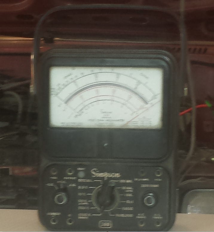
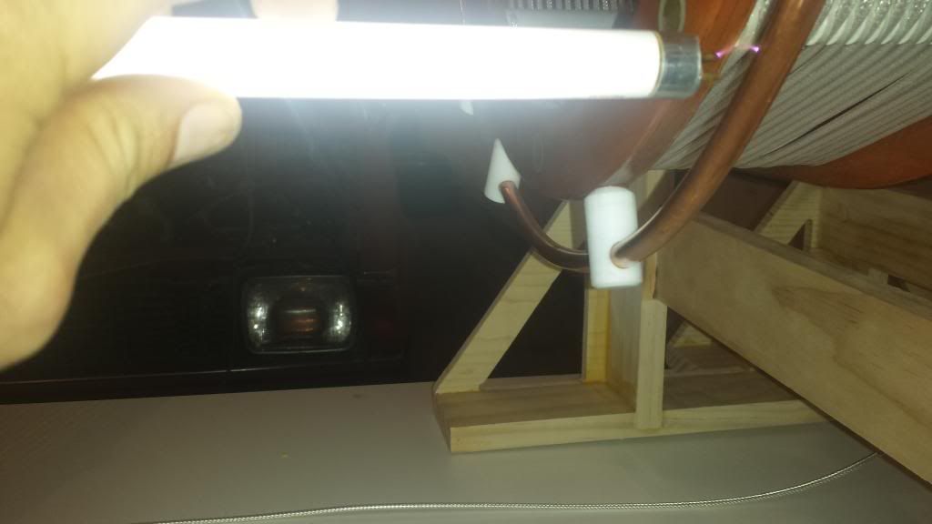
To measure the relative field strength we put an analog Simpson multimeter in between the two secondaries with no test leads. The RF emitted from the coils coupled into the multimeter circuitry, moved the indicator needle, and proved to be a suitable measuring device. Pictured below:
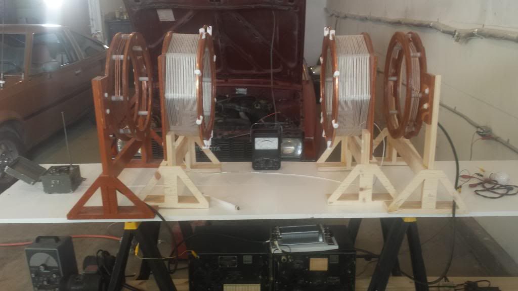
The Simpson was placed in the middle of the secondaries, but outside the direct path between the secondaries. This way it wouldn't be in the area of field cancellation. The exact location of the meter was experimentally determined. We moved the meter back and forth until the maximum strength was still on the meter's needle movement range. (Otherwise the meter would be pegged.)

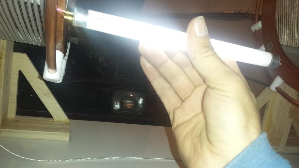
Its important to get the phasing of the coil connections correct. When we initially connected the coils, we had the phasing wrong and got a non-desirable field distribution. What happened was the two fields were not radiated in opposite directions, and one of the secondaries was resonating at the expense of the other. A quick test with a flueroescent bulb showed the field strength was larger from one secondary than the other. So we reversed the connections on one of the primaries to get the proper phasing. To verify the phasing of the coils is correct, you can test by moving a fluorescent bulb in between the two secondaries. Near the middle of the secondaries there should be a dark spot in the bulb. That is, both ends of the bulb should be lit brightly but the center of the bulb should be dark or dim. Unfortunately I wasn't able to catch this event on camera, but I'm going to try to in the future.
Now onto the field tests. There are a large number of variables that influence the resonating of the coils: the frequency, the coupling between each primary and secondary(distance), the distance between each set of coils, driving the coils in series or parallel, the amount of capacitance used in the primary tank circuit, the coupling between the driver (transmitter) and the primary tank circuit, the amount of stray capacitance, and any number of other variables.
For our tests we varied three of these parameters: frequency, amount of primary capacitance, and the spacing between each primary and its respective secondary.
The first round of tests we fixed the coil spacing between the primary and secondary at 2", this being the closest the conductors could actually be to each other with the coil forms butted up against each other.
A fixed amount of capacitance was added to the primary tank circuit, this being in the form of an air variable capacitor. The capacitor shaft was turned between 0 and 180 degrees. 0 degrees being minimum capacitance, and 180 degrees being maximum capacitance. Then for each quantity of capacitance the frequency was incrementally changed and the field strength recorded to determine the maximum field reading, as determined by the AC voltmeter placed in between the coils. So for instance the data was taken as follows:
1. Add discrete amount of capacitance to primary tank.
2. With the transmitter, incrementally change the frequency driving the coils. Adjust the transmitter (dip the plate). For each frequency record the AC voltmeter reading.
3. Continue to sweep the frequencies with the same amount of capacitance until a peak AC reading is achieved. This the frequency that gives peak output for the fixed amount of capacitance.
4. Change the amount of capacitance used in the primary tank.
5. Repeat above tests, again searching for the peak output frequency.
6. Continue making capacitance vs. frequency measurements. Note the combination of capacitance and frequency that yields maximum field strength.
7. Change the coupling between the coils (distance) and repeat all above measurements.
 Please help support my indiegogo campaign: Cosmic Induction Generator
Comment
-
Graphs of Data
The first few data sets are shown below:
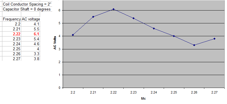
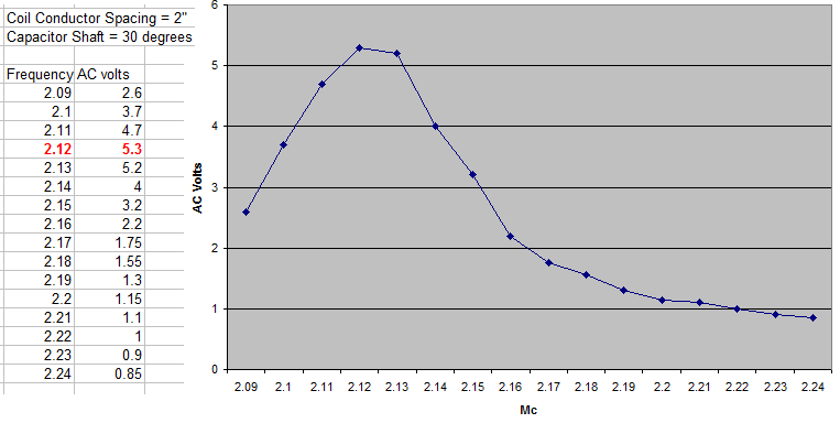
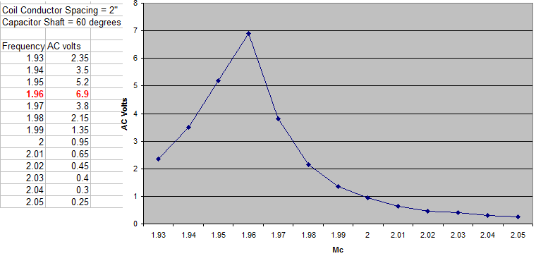
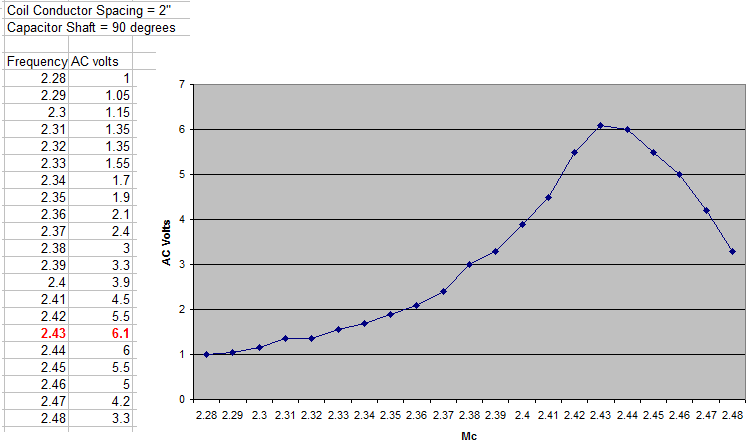
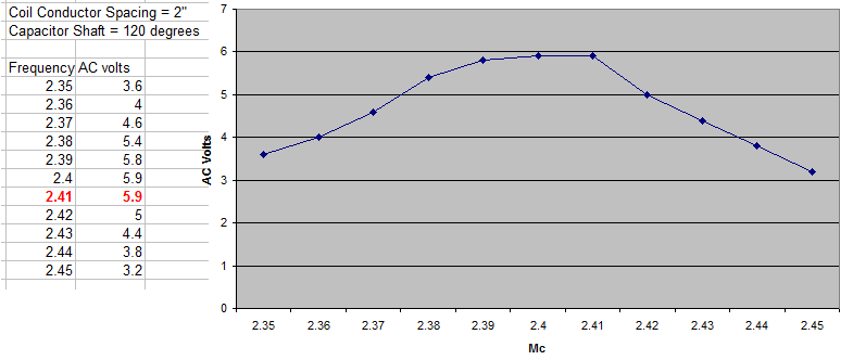
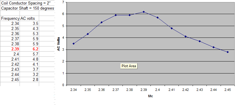
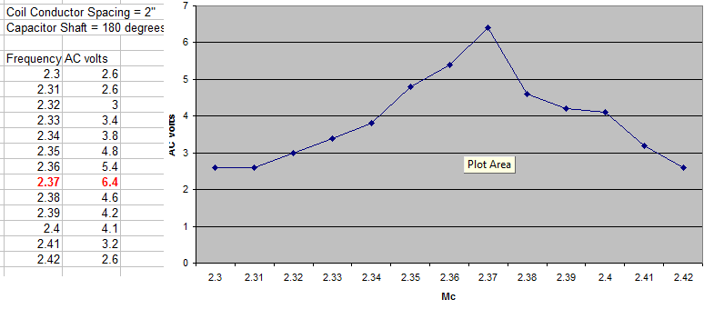
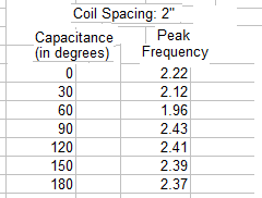
It is Interesting to note the different sharpness of peaks with different amounts of added capacitance. The sharpness of the peak is an indication of the Q of the primary tank circuit. Also coming into play is the interaction between the primary and the secondary. Previously it was experimentally determined the secondary free resonant frequency to be 2.29 Mc. Adding capacitance to the primary pulls the resonant frequency of the system off from 2.29 Mc. A summary of the quantity of capacitance vs the resonant frequency is below:
This was only a limited gathering of data, showing there is a large amount of experimental data to collect before any conclusive results can be drawn. The goal is to determine the optimum combination of parameters to yield the maximum power output. In our case we used the analog AC voltmeter as a field strength meter to quantify the power output.Please help support my indiegogo campaign: Cosmic Induction GeneratorComment
-
Disappearing energy
The last set of tests was the most interesting. The idea was to compare the the power output of the TCS transmitter, with the current circulating in the primary tank circuit, and to the field strength. The metrics we used to collect the data were as follows:
Transmitter power output- measured by DC plate current
Primary tank circuit current - measured by RF Ammeter on TCS
Field Strength - measured by Simpson AC voltmeter placed in between two secondaries
For this round of tests we used 3 controls on the TCS transmitter to make adjustments: plate tuning, frequency, and coupling to the coils. The plate tuning takes the form of a variable capacitor that adjusts the plate to resonance. The coupling from the transmitter to the coils is accomplished by the use of a variable mutual inductance. It is called a variometer and adjusts how much power is transferred from the plate tank circuit to the primary tank circuit.
The frequency was varied in large increments between 1.85 and 2.45 Mc. For each frequency, first the external variable capacitance was adjusted for the maximum amount of current circulating in the primary tank circuit, as measured by the RF ammeter. Then the plate circuit was retuned to resonance. Then the external capacitance was adjusted again, and the plate retuned again. This was done back and forth until the maximum current was flowing in the primary tank. Next the coupling between transmitter and primary tank was adjusted, to again attain the max amount of current in the primary tank. Finally, small adjustments were made to the the external variable capacitor to get the maximum amount of field strength. The graph is shown below:
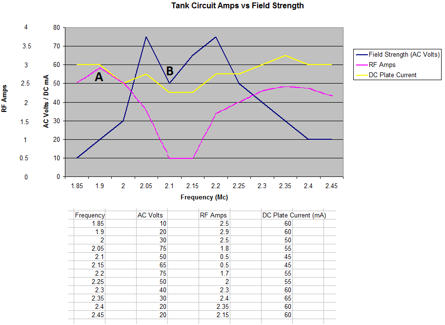
First you'll notice the DC plate current stays relatively constant. This because the transmitter was always tuned to minimum plate current (which is resonance for a parallel resonant circuit). So the power output from the transmitter stayed relatively constant.
When you see large peaks of RF current, there is a large amount of current circulating in the primary tank, which sounds like a good thing, but that is energy that is trapped in the primary tank circuit and isn't being coupled from the primary to the secondary. The AC volts obviously represents the field strength.
There are two key points of interest:
Point A: here there is a large amount of current flowing in the primary tank circuit, as evidence by the peak in RF amps. Also notice the low field strength (AC volts) because that is energy that isn't being coupled to the secondary and radiated.
Point B: this is the key point of interest. Note the field strength- it was at its peak reading and suddenly takes a 30% dive. At the same time more energy is being delivered from the primary tank circuit to the secondary, as evidenced by the reduced amount of RF amps flowing, whiche the DC plate current stays relatively constant. So the field strength dips, the amount of energy being radiated goes up, and the overall power delivered by the transmitter stays about the same. Energy disapearing! This is what Eric terms as energy flowing into counterspace. This is also the point where the magic of the "galaxy in the bulb" happens!
Here's a couple pictures showing us drawing a small flame off the secondary:
More testing is to be done....
Any comments or criticism is welcome!Please help support my indiegogo campaign: Cosmic Induction GeneratorComment
-
couple questions John,
what is the model of receiver? and signal generator?
The plate load voltage & current is from the signal generator?
The receiver is outputting to a speaker at all times yes? then the it's also running the signal thru an amplifier, the speaker is loading the output as it's part of the circuit, the attached measurement device (volt meter) is also now part of the circuit as well. As you can see it gets fairly complex sorting out what's passive and what's not.
For now I don't see a 'disappearing' energy, there is internal circuits of the receiver to factor in esp since it's driving a speaker load. the mu of the amp circuit needs to be calc'd, and then you have the output transformer characteristics.
It may seem like I'm discounting the tests, I'm not, I think a far more rigorous work up needs to be done to factor out and see what the rest of the system is doing.Comment
-
Eric Dollard Announcement Mailing
Latest Eric Dollard announcement mailing:
6 New Dollard Photo Albums, New Interview and Energy Disappears into Counterspace! Sent Wednesday, February 26, 2014
TOPICS:- 6 NEW ERIC DOLLARD PHOTO ALBUMS
- NEW FACEBOOK Q & A VIDEO INTERVIEW
- COSMIC INDUCTION GENERATOR GRAPHS, PHOTOS, DETAILS
It's was a fun weekend getting together with Eric Dollard over in the Seattle area. We got a lot of his photos onto his Facebook page. There are six new albums...
Western Electric TD2 Bell Telephone Transmitters: https://www.facebook.com/media/set/?...2675483&type=3
This is what used to be hooked to the lines/poles that EPD Laboratories will be salvaging wire from for the Advanced Seismic Warning System.
Life in the Desert in Arizona: https://www.facebook.com/media/set/?...2675483&type=3
Life in the Desert in Lone Pine: https://www.facebook.com/media/set/?...2675483&type=3
Life in the Desert on the Walker Pass Telephone Trail: https://www.facebook.com/media/set/?set=a.284561635034655.1073741836.241486692675483& type=3
Life at Camp Gregorio: https://www.facebook.com/media/set/?set=a.284562308367921.1073741837.241486692675483& type=3
This will be the site for the next seismic system (after the one that will be on the govt land that was just funded by Indiegogo).
Secret Location - Bell Telephone: https://www.facebook.com/media/set/?set=a.284568408367311.1073741839.241486692675483& type=3
I took some video I'll get out when I get a chance to compile it. Really INCREDIBLE facility. Was like taking a Time Machine back to the 60's. The man who rebuilt this all by himself had all decades but the old relays chattering about, etc... pretty wild!
New Interview - Eric Dollard Answers Facebook Questions - Feb 23, 2014
Eric Dollard Facebook Q & A on 2014-02-23 - YouTube
There is another live video interview Eric did with the Tesla Science Foundation on the same day and I'll get a link out to that soon.
COSMIC INDUCTION GENERATOR - John Polakowski just posted some graphs,
photos and details on the recent tests he and Eric did at EPD Labs. One test shows what appears to be energy (a lot of it) disappearing right into counterspace.
Here are the 4 posts by John Polakowski:
http://www.energeticforum.com/251306-post1718.html
http://www.energeticforum.com/251307-post1719.html
http://www.energeticforum.com/251308-post1720.html
http://www.energeticforum.com/251309-post1721.html
They're in Eric Dollard's thread here if you want to see the whole conversation:
http://www.energeticforum.com/eric-dollard-official-forum/11855-eric-dollard.html
Sincerely,
Aaron Murakami
Eric P. Dollard - Official HomepageLast edited by Aaron; 02-27-2014, 05:32 AM.Sincerely,
Aaron Murakami
Books & Videos https://emediapress.com
Conference http://energyscienceconference.com
RPX & MWO http://vril.ioComment
-
Hi Madhatter,Originally posted by madhatter View Post
Thankyou for the questions. Please don't apologize, peer review is exactly what is needed to ensure scientific integrity and accuracy!
I actually apologize because I must not have made my post clear enough explaining how the tests were performed.
The receiver model we used was a TCS-12, made by Collins. The signal generator used was a Heathkit model IG102.
To better explain the test setup there were two different equipment arrangements:
Each setup did not involve the equipment from the other setup. So when the transmitter was being used the receiver was not being used and vice versa. So when data was being taken from measurements on the AC voltmeter, the Heathkit Signal generator was out of the picture and so was the speaker.
All that is being claimed is that the transmitter was delivering a certain amount of power, and that power did not show up in the primary tank circuit or in the field energy surrounding the coils, according to our measurement equipment. There is certainly the possibility that our measurement equipment was in error, or that the RF field energy was received by something we didn't account for, or some other scenario. The only claim is that we don't know where the power delivered from the transmitter went.
I also completely agree that more rigorous tests need to be performed, and that no concrete conclusions can be drawn, just that we observed a strange occurrence of data.
Any other questions or clarifications would be welcome, and I will answer them to the best of my ability.Please help support my indiegogo campaign: Cosmic Induction GeneratorComment
-
Thanks, what was used as the PS (power supply) for the TCS 12?Comment


Comment