If this is your first visit, be sure to
check out the FAQ by clicking the
link above. You may have to register
before you can post: click the register link above to proceed. To start viewing messages,
select the forum that you want to visit from the selection below.
@dr Green, you�re right, that is what the sting is, arcing to the fingers when the terminal is loosely held. I even received a slight burn through the insulation of the larger clamp, so the current can penetrate the insulation seeking a ground. Penetrate is the wrong term, it was if the current conducts through the (so called) insulation. One is better off to just to grab the metal. No problems. The larger the surface area of the held metal definitely helps. Yeah, less contact or varying the pressure of contact affects the brightness of the bulb.
Originally posted by Thomas Commerford Martin
The physiological effects of the high tension discharge are found to be so small that the shock of the coil can be supported without any inconvenience, except perhaps a small burn produced by the discharge upon approaching the hand to one of the terminals. The decidedly smaller physiological effects of these currents are thought to be due either to a different distribution through the body or to the tissues acting as condensers. But in the case of an induction coil with a great many turns the harmlessness is principally due to the fact that but little energy is available in the external circuit when the same is closed through the experimenter's body, on account of the great impedance of the coil.
The Inventions, Researches And Writings Of Nikola Tesla, Page 125-126
The Inventions, Researches And Writings Of Nikola Tesla, Page 125-126
Interesting.. I'll have to go find it & read it. -Thanks. There is certainly energy there!
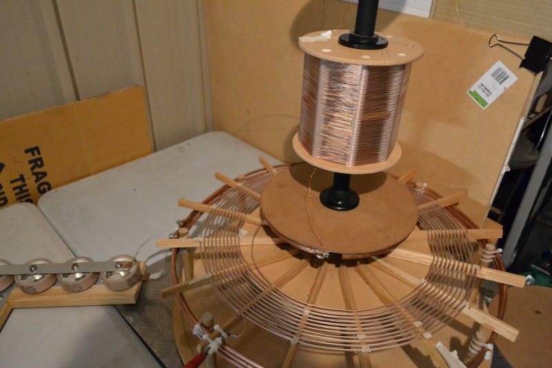
Spiral TMT:
Spiral TMT: Capacitive coupling from spiral coil to extra coil, via rings, here the rings are asymmetrical in this particular configuration. Here working on 1860Kc, however tuning for the elusive concatenated mode resonance is still ongoing. Nevertheless the bulbs on the output terminal are somewhat brighter than before.
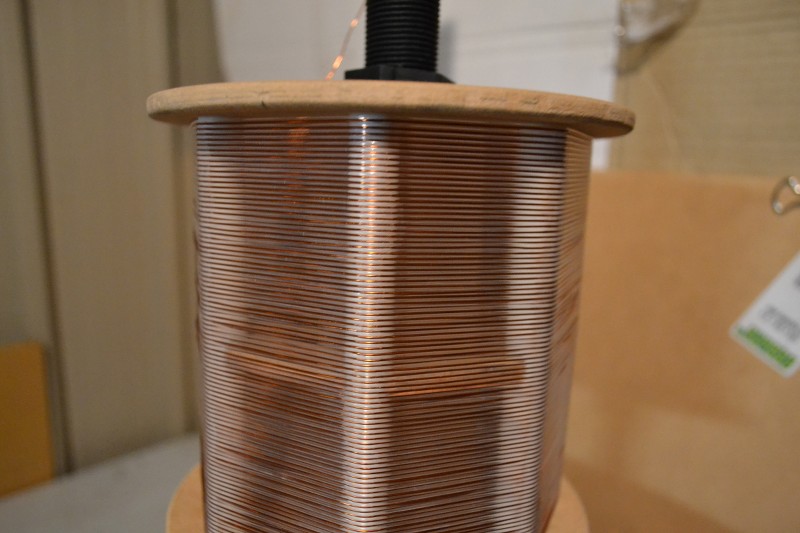
Extra Coil (version two, experimental)
0.5mm wire, 0.8mm gap, 94T, 140 x 140mm form, 40 meters long. Wire weight is close to that of the Secondary.
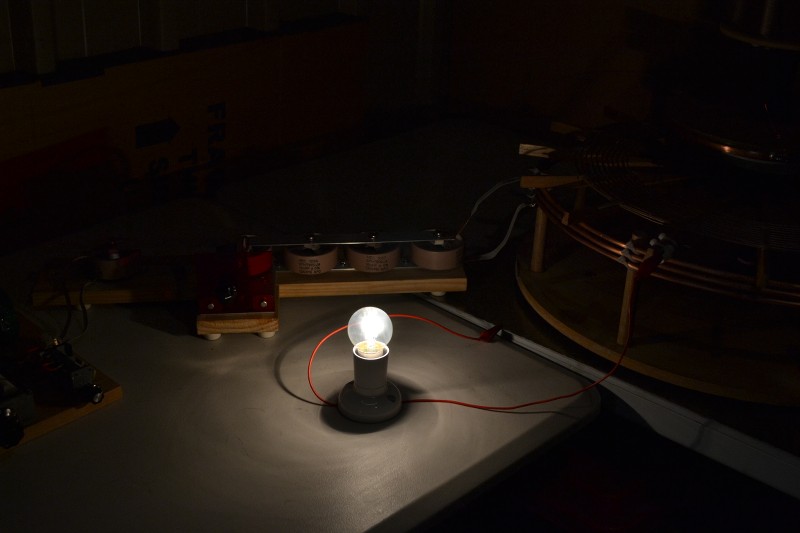
Small 240V, 25 watt filament bulb.
Super bright at full power! The camera�s auto shutter makes it look far less so, the colour is bright white.
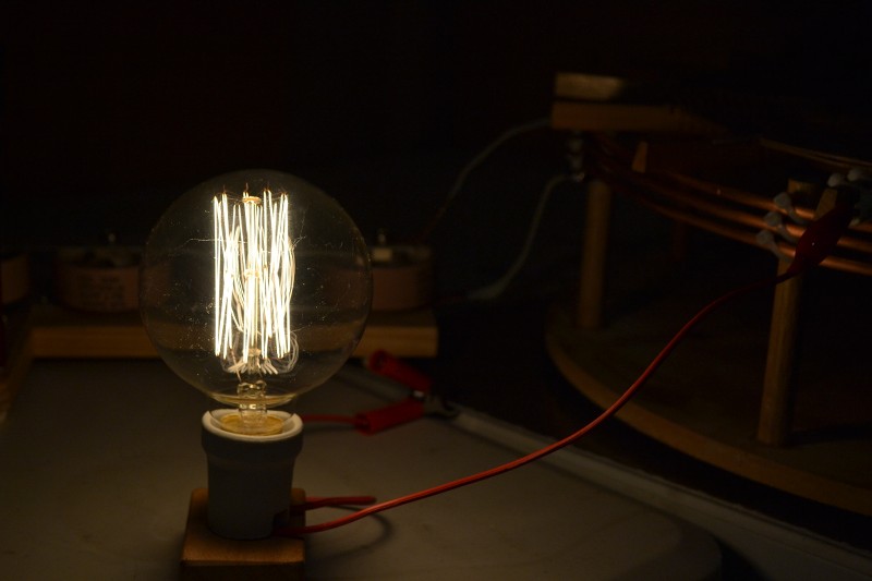
Long slender �vintage� filament bulb (25W)
Both �vintage style� bulbs are brighter than with ordinary 50 cycle 240V. The bulbs do get hot & they all light up just as well when connecting them to your body! - Even at full power you feel nothing. No headaches or odd feelings, almost seems to even make one feel a little better?
Round �vintage� filament bulb (25W)
Still playing with various configurations to optimise the output and tuning. Observation - even when using my very low power signal generator & amp, (not the transmitter) oddly one can feel a certain kind of warmth all around the extra coil against the hand when in resonance. With transmitter you can certainly feel it. Connecting the output directly to ground and readjusting for the impedance (pi network) up to 1 inch purple arcs can be drawn off the top terminal.
More later.
"Doesn't matter how many times you kick the coyote in the head, it's still gonna eat chickens". - EPD
Western Electric TD2 Bell Telephone Microwave Installation
A 3.8 to 4.2 gigacycle line of site microwave relay station. Total number of telephone channels 10,500. Station off the air and defunct. This is my introduction to Bell Telephone in High School. The wire line system that connects these stations together is what we're salvaging to make the telluric antenna out of for the Advanced Seismic Warning System.
Full restored and operational step by step crossbar and O Carrier system. This is the very system that came off of the long lines that we're salvaging for the Alexanderson antenna for the Advanced Seismic Warning System. Much of this I'm going to have to rebuild from scratch.
Observation - even when using my very low power signal generator & amp, (not the transmitter) oddly one can feel a certain kind of warmth all around the extra coil against the hand when in resonance. With transmitter you can certainly feel it. Connecting the output directly to ground and readjusting for the impedance (pi network) up to 1 inch purple arcs can be drawn off the top terminal.
Interesting. I feel a cooling, which is all the more interesting because your coil is wound in the opposite direction. Although I'm not convinced that's not a figment of my imagination, and putting hands in to try and repeat it detunes it etc, I have noticed it over several months when it's not something I'm ever thinking about otherwise, so it could be worth investigating further with a more reliable approach.
Nice job, those vintage style bulbs look nice too.
The (transmitting) coil is tuned to the design frequency of 1860 kc, but the tuning of the primary and secondary is not yet optimised. Transmitter is used alone in the video with focus on single wire filament lamp lighting as well as completely wireless operation of same through capacitive coupling to/from garden soil in a bucket.
Do you have a book in mind from Seely? I haven't quite connected to the modeling of the oscillating terms.
So do we just generalize h a little bit more to take in the �, 1/8, 1/16... rotations to pick off the transient terms?
j^n=(-1)^(n/2)
h=(-1)^(n/(2m)), 360/2^(m-1) angular rotations; m,n in positive integers.
(j^n)*h=(-1)^(n/2)*(-1)^(n/(2m))=(-1)^(n(m+1)/(2m)) ? Something like this in general.
Or do we start pushing towards non-integer multipliers? I almost see this but not quite. I love it, keep going.
You're definitely seeing ahead in the program here. Imaginary numbers can ultimately be eliminated completely by using one raised to a fractional exponent.
An example - fourth root of positive one can be expressed as one to the one-fourth power. But then, this has four roots. One to the one fourth, one to the two fourth, one to the three fourth, and one to the four fourth. Hence, all four roots with no imaginary numbers.
I have much information on this written but it's very slow getting out. I think it will really fascinate a lot of people. We will see.
73 DE N6KPH
SUPPORT ERIC DOLLARD'S WORK AT EPD LABORATORIES, INC.
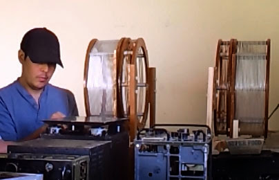
Aaron Murakami - assembling shock mounts for Navy TCS Transmitter
This is a graph of recent experiments with the Cosmic Induction Generator at EPD Laboratories, Inc. The curves indicate the disappearance of energy into counter space or what the physicists would call a different dimension.
This counter space exists in the neutral plane between the two coils. This is the place where the galaxies originate. It appears we have a dimensional transformer.
SUPPORT ERIC DOLLARD'S WORK AT EPD LABORATORIES, INC.
There is no Poynting Vector on a resonant transformer - it is cancelled out.
Electromagnetic relations cannot be utilized in this situation.
There is no velocity in space. The velocity is in counter space in per cm per second.
73 DE N6KPH
This is not necessarily true, considering the answer depends upon how you examine the situation.
Electrical resonance in its most basic form is a "trap" for electrical energy. For a transmission line, this trap consists of two boundaries, the source and the load. Since the Tesla transformer "transmission line" has an impedance mismatch between its source and load, energy is reflected back to the source. That is, the initial propagating wave cannot keep moving forward, as one would expect for an infinite line or a line terminated resistively at its natural impedance. Thus we have TWO Poyntine vectors: one moving forward and one backwards.
The superposition of these two waves mathematically sum to form a so called "standing wave." At this point, the nature of the Poyntine vector becomes obscured from this condition. It is however not a complete enigma. Rather than a divergence of S at the end of the line, like a resistively loaded line, we see a continuous circulation of S in the resonant structure, with a minor amount of divergence therein from ohmic and radiation resistance losses (dampening). So did the Poyntine vector just up and disappear? I would say no.
Is the resonant solenoid really non-electromagnetic? I would have to point out that while the mode of the EM energy has changed from TEM to say TE or TM, it is still electromagnetic in nature. However, if you are referring to the angles of E, B, and S, you might be on to something...
On a theoretical tangent, let's examine the solenoidal resonator for conditions of series and parallel LC resonance. The key points of interest are the phases of inductive and capacitive currents/voltages with reference to each other AND the source. It becomes a "godhead trinity" so to speak.
In the general case, most coils are resonated as parallel LC, which means that coil impedance is high, with losses lowering the impedance slightly to allow energy to enter from the source. If no losses were present, divergence of S from the coil would be zero, as would be divergence from the source into the resonator would be zero, since no load is seen to either. A resonator in this condition has the vector sum of its reactance voltages in phase with the source, leading to a DC like condition of (+1)-(+1)=0. That is there is no current, as impedance is infinite (think two batteries of equal voltage connected positive to positive, negative to negative, there is no current flow. So what does this mean for telluric current? There should be a minimal amount in this condition.
Flipping the situation around to series LC resonance, coil impedance drops to the AC resistance values thus coil reactance appears to be zero. At this point source divergence is very high, if the coil's combined radiation and ohmic resistance is close to the natural impedance of the source. This is the opposite of the previous example. Here the resonance trap takes some energy to maintain its operation with the rest of the energy radiated as heat or RF. The reactance voltages in this case sum to zero and the coil appears as resistive. Telluric currents in this condition should be maximal.
Getting series resonance isn't easy for a solenoidal resonator. Instead, a hybrid method can be employed, using parallel LC resonators as transmission lines and intentional impedance mismatching to allow for reflection. This is probably why when you use two concatenated coils, extra and secondary, you get more RF current into the ground.
The net result is a horribly complicated form of transmission line theory and lumped element analysis.
Optimal parameters for this situation are not in "the books." It's more of an empirical situation to see what works then use analytical thought to assemble the relations into math. This is probably why Eric has yet to provide the mathematical frame work for the coils as telluric transmitters. One would naturally guess that FTL is unlikely, as is anything "longitudinal." However it would be interesting to see the propagation speed. Considering permittivity of the earth isn't constant, refractions should be overwhelming. Empirical data on this subject is dearth at best, however, the data could really turn science upside down if certain assumptions on why this should fail turned out wrong.
S, in general, can be thought to represents the photon, the basic idea of energy. So when talking about a solenoidal resonator, if there is "energy" present there is a Poyntine vector, and there can certainly be more than one Poyntine vector at any one time. To say that it has canceled out is at best misleading, unless further explained. The only condition that would allow for such is when energy just up and disappears, blinking out of existence so to speak. An unusual situation which may or may not be possible depending upon the circumstances.
If the situation is as you say, non-electromagnetic, I would agree that there could be no Poyntine vector, since there could be no EM energy without one. The questions one comes to after the contemplation of such an event, would be what form does the EM energy take? How does it traverse through space? How does one convert it back to EM?
If the purported condition is real, energy in the form of a photon, has either a second form or space for its movement. From your original comment, It would appear you believe in the latter.
For the FLT "beliebers", this "other space" has one of three possibilities: 1) speed of the photon is = C (most likely), 2) speed of the photon is >C (highly unlikely), 3) There is no velocity as distance is zero or time is zero (more likely than 2).
Regardless of "what if" excursions and terse comments, there is indeed a Poyntine flux in a solenoid resonator. It is possible that some energy is "displaced" though another space, but it doesn't mean the entire S flux has altogether disappeared.
This is a graph of recent experiments with the Cosmic Induction Generator at EPD Laboratories, Inc. The curves indicate the disappearance of energy into counter space or what the physicists would call a different dimension.
This counter space exists in the neutral plane between the two coils. This is the place where the galaxies originate. It appears we have a dimensional transformer.
It�s been very interesting to see all the pictures of the various Rat Camps, Landing zones and the secret Bell Telephone installation. - Something not really seen on the forum before! Certainly there is some beautiful wilderness out there, absolutely stunning! The Corolla looks in really good shape, now that the pictures show it more clearly. I love the �V - whiskers� out on the front.
Nice to see some data from JP�s CIG. From the graph the dip in RF amps and plate current seen at 2.1-2.15Mc (at resonance I assume), one would normally see the field intensity peak here, (with a single coil), but since two coils are facing each other / interacting, the field intensity drops at a certain frequency, right on 2.1Mc. � Energy disappearance into counter space. This using just the Primary Tank & Secondary coils. � I�ll have to get the other half of my TMT cranking real soon.
"Doesn't matter how many times you kick the coyote in the head, it's still gonna eat chickens". - EPD
S, in general, can be thought to represents the photon, the basic idea of energy. So when talking about a solenoidal resonator, if there is "energy" present there is a Poyntine vector, and there can certainly be more than one Poyntine vector at any one time. To say that it has canceled out is at best misleading, unless further explained. The only condition that would allow for such is when energy just up and disappears, blinking out of existence so to speak. An unusual situation which may or may not be possible depending upon the circumstances.
If the situation is as you say, non-electromagnetic, I would agree that there could be no Poyntine vector, since there could be no EM energy without one. The questions one comes to after the contemplation of such an event, would be what form does the EM energy take? How does it traverse through space? How does one convert it back to EM?
If the purported condition is real, energy in the form of a photon, has either a second form or space for its movement. From your original comment, It would appear you believe in the latter.
For the FLT "beliebers", this "other space" has one of three possibilities: 1) speed of the photon is = C (most likely), 2) speed of the photon is >C (highly unlikely), 3) There is no velocity as distance is zero or time is zero (more likely than 2).
Regardless of "what if" excursions and terse comments, there is indeed a Poyntine flux in a solenoid resonator. It is possible that some energy is "displaced" though another space, but it doesn't mean the entire S flux has altogether disappeared.
All very interesting.
But I would simply suggest you go back and read the Nikola Tesla and the Alexanderson work in their own words. I would also suggest going back and reading the previous posts which will take some time.
You seem to miss the point of the theory Eric is talking about and the point Tesla himself was making back in 1892 or so in those lectures which are easily read on-line.
You can of course disagree with Tesla himself, plenty of people did and still do.
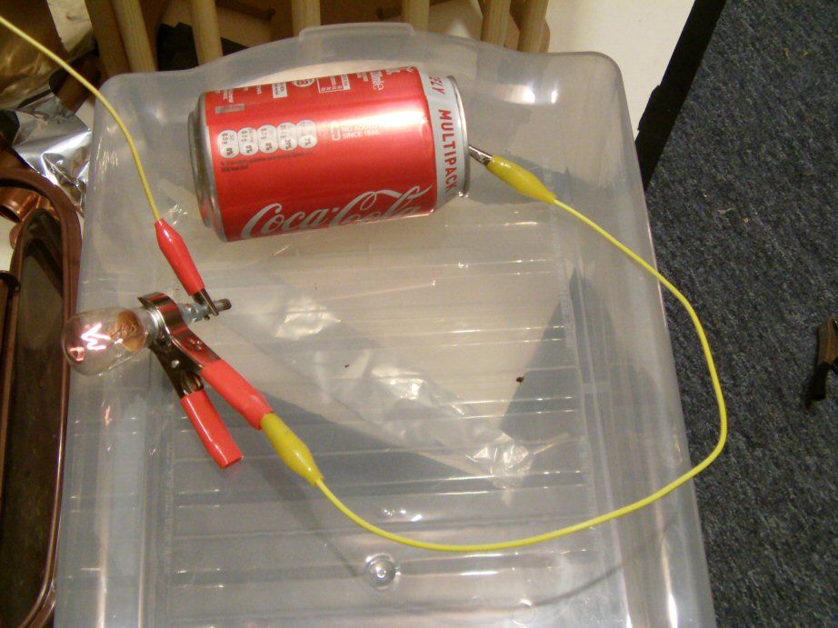
The (transmitting) coil is tuned to the design frequency of 1860 kc, but the tuning of the primary and secondary is not yet optimised. Transmitter is used alone in the video with focus on single wire filament lamp lighting as well as completely wireless operation of same through capacitive coupling to/from garden soil in a bucket.
An empty coke can used as capacitance on the lamp for reference of its size. Obviously bigger objects/surface areas yield better results.
Great video, particularly how you show the various ways which the light bulbs can light. The light bulb lighting up via the soil in a bucket is a fine demonstration. - I�ll have to try some of those tricks myself.
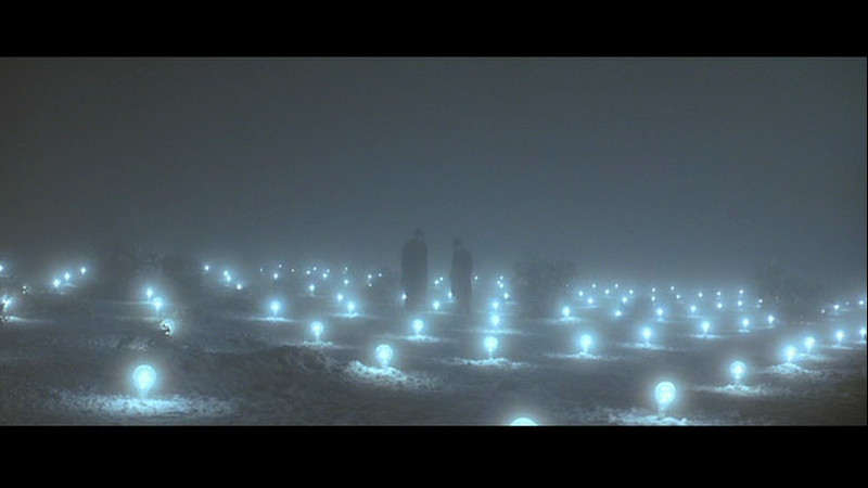
It reminded me of that wonderful scene from the horrible movie, �The Prestige�.
"Doesn't matter how many times you kick the coyote in the head, it's still gonna eat chickens". - EPD
There is a lot more to come - John P. will be posting it all soon - more graphs and a write up of the details.
I'll be posting some more pics and even video of the Bell Telephone system. It was a TRIP! It seriously was like Willy Wonka's Electronics Factory. Was expecting some Oompa Loompas with pocket protectors and multimeters to pop out of nowhere and start doing cartwheels down the isles.
There was a program running to simulate a lot of phone calls on rotary dial phones - all the relays chattering, etc...
The man who put all that together and rewired MANY 10's of thousands of individual connectors has some serious talent. Was cool - drove up to the front of the driveway to his home and was met with a railway crossing that opened up to let me in.
Those pics are mostly of the 1960's era phone system I believe - he had all decades.
 Tweet
Tweet


Comment