 Tweet
Tweet
Originally posted by Sputins
View Post
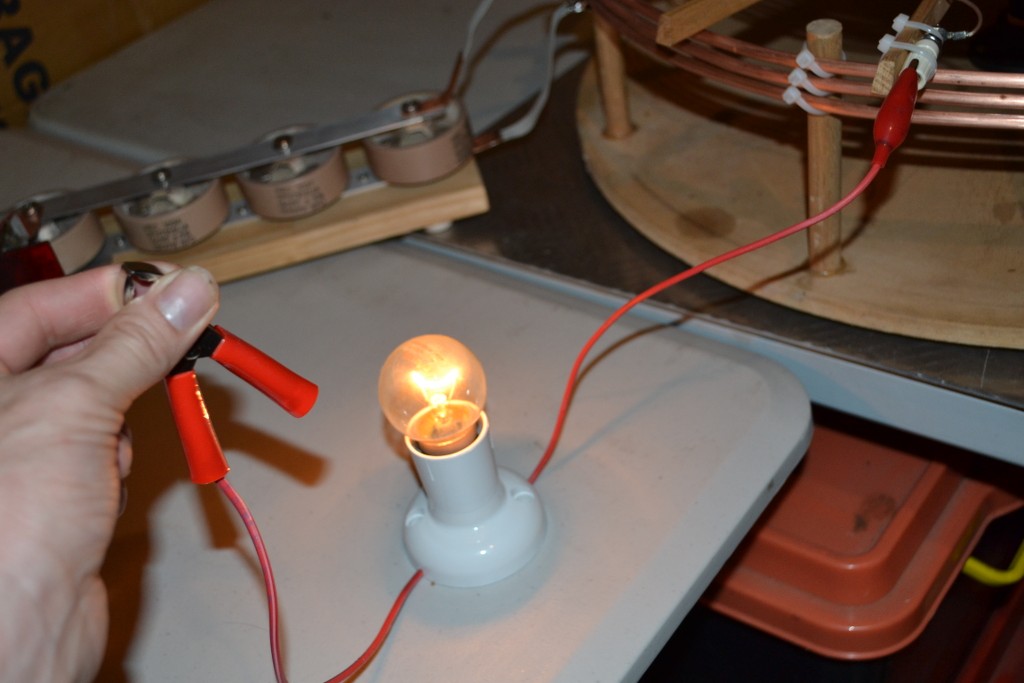
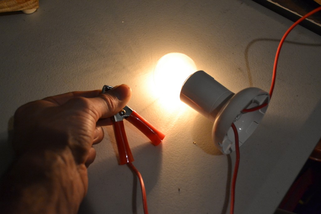
I would think that the burning is a bit of arcing into your finger, that can sting a bit, but as you say once contact is made and you hold on tight then nothing can be felt. If you use varying power levels you should also be able to see the difference in bulb brightness between "light" connections and gripping it tight with both hands etc, which translates to the importance of all the (ground) connections ideally being soldered and as broad as possible like Eric says, sheet or strip from the coil output to ground etc. I'm still using alligator leads but I think you will find in an obvious way that ideally you shouldn't.
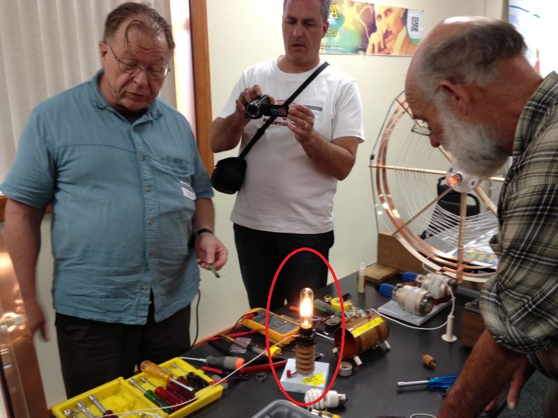
An extra coil can make a significant difference in output for the same input. Personally I've also found the DMT/TMT style coils to be a lot better than my flat spirals, so it should be quite impressive with your amp. I've gotten a lot worse results than these using spark gaps and thousands of volts in the past, so things are progressing nicely I would say, considering it's now also possible to use the same setup for transmission of CLEAN intelligible signals. It's taken long enough to finally come up with an amplifier that's up to the job though! We'll find out how much more power can be squeezed out of it when my power resistors arrive hopefully tomorrow.


Comment