Announcement

Collapse
No announcement yet.

Eric Dollard

Collapse
This is a sticky topic.
X
X
 
  • Filter
  • Time
  • Show
Clear All
new posts

  • Hello Eric,

    Would it be possible for you to answer one question regarding one project which you're involved quite while ago (20 some years). I did replicate this setup together with log periodic antennas, exactly as you have design them. By the way, this is brilliant and they indeed "work" without power being connected. I'm talking about Multiwave Oscillator. I was hoping to ask during the webinar but there was no time for live questions.
    There was a variation of this circuit with two small (1/8") spark gaps at the antennas feed. What would be the benefit of such setup versus single spark gap. I have two setups running, both using bipolar TC but one is spark gap driven and the other is semi solid state (with spark gap as well).

    Thank you

    Vtech
    Attached Files
    'Get it all on record now - get the films - get the witnesses -because somewhere down the road of history some bastard will get up and say that this never happened'

    General D.Eisenhower


    http://www.nvtronics.org

    Comment


    • This is the circuit I'm talking about -
      Attached Files
      'Get it all on record now - get the films - get the witnesses -because somewhere down the road of history some bastard will get up and say that this never happened'

      General D.Eisenhower


      http://www.nvtronics.org

      Comment


      • Peter Lindemann's interview of Eric Dollard video

        July 30, 2013 - Eric Dollard Live Interview by Peter Lindemann - YouTube

        That is the video from Peter Lindemann's interview with Eric Dollard on July 30th, 2013. It's not the best but is from a streaming broadcast so the audio doesn't match the video perfectly.
        Sincerely,
        Aaron Murakami

        Books & Videos https://emediapress.com
        Conference http://energyscienceconference.com
        RPX & MWO http://vril.io

        Comment


        • Originally posted by T-rex View Post
          1. I gave an analysis of the Colorado unit on the EG Forum some time back and must find it. The system there was about 95Kc unloaded and 45Kc with the full size bast and ball.

          2. For 1860 the turns will be proportionally less. The ratio of 45 to 1860 is square rooted to scale inductance and capacity. 0.02419 tge ratio, the root is 0.15553. Hence the inductance and capacity is this time the values given for Colorado. The turns will come about accordingly, in general the length of wire varies with frequency. This is going to be the principle parameter.

          3. What you are seeing as "Radiation" is the change in Earth potential around ground connection. The Earth is emitting lines of force.
          Thanks Eric. Your analysis is here

          http://www.energeticforum.com/renewa...tml#post202262

          The reason I'm asking that is because if I scale it down then I'd like it to be as accurate as possible. I sent a file to Aaron by e-mail, I don't know if you got it. The way I've calculated it so far is to start with the end frequency with mast and take the ratio of that to the secondary alone frequency, then the secondary is scaled down from the full size secondary alone. So I'd like it to be done right and end up at the right frequency, or am I just being too fussy in wanting to find a more exact figure. I'm guessing you must have calculated the end frequency with mast from the inductance and capacitance rather than Tesla stating the frequency, the closest I could find was 45.496 kc and I can't remember what now but I think Tesla was referring to something else there.

          If I start with 45 kc and scale to 1860 kc, I get a secondary diameter of 36.2cm with a required extra coil inductance of 2.7mH and 67.2pF end capacitance (using Wheeler's formula for inductance).

          If the physical dimensions of the extra coil are scaled down by 0.15553, that gives an extra coil of 39cm diameter and 2.7mH which is the target inductance, but 100 turns and 122 metres of wire. I haven't calculated too many variations yet but so far I can't seem to end up at 2.7mH without an excessive number of turns on a smaller frame.

          Thanks for your help, and I was loving some of your answers in the live interview just now!
          http://www.teslascientific.com/

          "Knowledge is cosmic. It does not evolve or unfold in man. Man unfolds to an awareness of it. He gradually discovers it." - Walter Russell

          "Once men died for Truth, but now Truth dies at the hands of men." - Manly P. Hall

          Comment


          • I forgot to mention, this is a clip from a BBC Horizon episode called The Core which might be of interest

            What's it Like at the Centre of the Earth? - Horizon: The Core - BBC Two - YouTube

            The full episode is available here but they only allow a 5 minute preview before prompting you to install their web player to see the rest.

            Watch Videos Online | The Core - BBC Horizon | Veoh.com
            http://www.teslascientific.com/

            "Knowledge is cosmic. It does not evolve or unfold in man. Man unfolds to an awareness of it. He gradually discovers it." - Walter Russell

            "Once men died for Truth, but now Truth dies at the hands of men." - Manly P. Hall

            Comment


            • AM CW Transmitters.

              Hello Eric.

              I’ve just watched your presentation video from the recent conference. It was very well put together, I loved it, the phases of the moon analogy really cements a basic understanding of the Four Quadrant Theory. I thought it was very good value as well, I hope many purchase it & the proceeds fill your pockets! (And the Lab).

              I know you want to see results, or see the work in progress thus far from those around the world, those working on the various EPD type projects, (CRI, CIG, TMT, & the Cosmic Ray Detector). Some have gone somewhat quiet due to the recent ‘trouble’ but let’s hope they return soon.

              I’ve been quietly working away (when I have available time and funds) constructing a power supply and an AM transmitter. Sometime ago you said that the ‘wright of passage’ was to either construct a Crystal Set Radio (hence the CRI) and / or to build a 100 Watt AM transmitter as a place to start.

              So I’ve been studying / learning about and AM CW tube transmitters (Boat Anchors). I’ve still much to learn on the subject, however I’ve nearly completed (await the arrival of some mA panel meters) construction of my first 100 Watt CW AM Transmitter and the matching power supply to go with it. (6.3V Filament supply, B+ low 250-300V, B+ high 750V).

              - This transmitter is a two stage transmitter, using a 6AG7 tube and two RCA 807 tubes in parallel. (Not push-pull right now, that will come later with more experience). The transmitter will be operating on the 160 meter band, (In my case 2 Mcps) and / or with interchangeable oscillator coils for 80 & 40 meters. Rather than using a crystal I’m also building a broadband VFO (1M – 21M Cps). This VFO is solid state, though which you wouldn’t like, but I’ve got to work with the equipment I already have & can afford. Once my frequency is determined / established, I can lock it in and go without the VFO.

              So the transmitter power amp stage (x2) 807 tubes will drive the tank circuit of the primary coil(s) of the either a TMT or CIG. (The CIG actually). Later, once I have more experience with the system, I have a couple of much more powerful transformers (extracted out of scrapped laboratory equipment) with 2500 Watt (plus) plate supplies, to be used with 304 tubes. (The 807’s can drive the 304’s). This will come later, when I know exactly what’s going on, & what I’m doing as I don’t want to electrocute myself dead in the garage!

              So over the weekend, I’ll take some photographs to show my recent progress, along with the basic schematics and post them here.

              I think this is what is needed most of all now, to return to practical activities of building, experimenting and the sharing of results.

              Take care.
              Sputins.
              Last edited by Sputins; 08-02-2013, 10:57 AM.
              "Doesn't matter how many times you kick the coyote in the head, it's still gonna eat chickens". - EPD

              Comment


              • 6sn7 Triode Driver


                Comment


                • Mwo #1085

                  Two spark gaps preserve the balance/2 phase form of oscillation. Everything must be absolutely symmetrical.

                  KEEP THE QUESTIONS COMING
                  SUPPORT ERIC DOLLARD'S WORK AT EPD LABORATORIES, INC.

                  Purchase Eric Dollard's Books & Videos: Eric Dollard Books & Videos
                  Donate by Paypal: Donate to EPD Laboratories

                  Comment


                  • Dr Green #1088

                    I am not in a position for much calculation now. The Colorado unit scaling is based upon a square root because L or C vary each with the square root since the frequency is based upon the square root of the product of LC. Try scaling the total wire length on each coil & see how that works out.

                    KEEP THE QUESTIONS COMING
                    SUPPORT ERIC DOLLARD'S WORK AT EPD LABORATORIES, INC.

                    Purchase Eric Dollard's Books & Videos: Eric Dollard Books & Videos
                    Donate by Paypal: Donate to EPD Laboratories

                    Comment


                    • Sputins #1090

                      Great on your efforts. I am envisioning a ham telluric net on 1860. The 807 is a great tube. 5933 & 1625 are basically the same. All are high voltage versions of the 6L6G. I will be back in the bush soon, because of the treachery that I am enduring. I might not come back out. The Gang of Four have done much damage and I have no more interest in these CIG things. It is best that I find another coyote and we both avoid human contact. By the way, Aaron has suffered greatly so give him all your support.

                      73 DE NGKPH

                      KEEP THE QUESTIONS COMING
                      Last edited by t-rex; 08-02-2013, 11:02 PM. Reason: edited tube number
                      SUPPORT ERIC DOLLARD'S WORK AT EPD LABORATORIES, INC.

                      Purchase Eric Dollard's Books & Videos: Eric Dollard Books & Videos
                      Donate by Paypal: Donate to EPD Laboratories

                      Comment


                      • The Gang of Four

                        Warning, (LAMARE)

                        Aether Force is using my name and saying things that I never said. This organization was formed to destroy my efforts by the Gang of Four, names to be given very soon.


                        Gang of Four - Wikipedia, the free encyclopedia

                        All material about me they put out is fraudulent. An insane and dangerous psychopath, aka Techzombie, is the source of most of this effort aided by others. Spread the word about "AETHER FARCE DOT NEM!"

                        Do not get involved with them, they are "The Kiss of Death."

                        See this identity theft: https://www.facebook.com/photo.php?f...levant_count=1
                        Last edited by t-rex; 08-02-2013, 09:07 PM.
                        SUPPORT ERIC DOLLARD'S WORK AT EPD LABORATORIES, INC.

                        Purchase Eric Dollard's Books & Videos: Eric Dollard Books & Videos
                        Donate by Paypal: Donate to EPD Laboratories

                        Comment


                        • Originally posted by T-rex View Post
                          I am not in a position for much calculation now. The Colorado unit scaling is based upon a square root because L or C vary each with the square root since the frequency is based upon the square root of the product of LC. Try scaling the total wire length on each coil & see how that works out.

                          KEEP THE QUESTIONS COMING
                          The way I understand it is this: The secondary frequency is raised by the extra coil, so from what I can gather the extra coil has to be a certain inductance.

                          Full scale frequency = 45000 cycles/sec
                          Scale frequency = 1860000 cycles/sec
                          Ratio = 0.024...
                          Square root = 0.15554...

                          Full scale secondary frequency = 42800 cycles/sec
                          Diameter = 15 metres
                          Height = 1.0668 metres
                          Number of turns = 16 (Based on Tesla's description and the coil measurements the 17th turn is "excluded" and is on the top insulators - including that would make the coil height nearly double in the calculations)
                          Conductor length = 753.98 metres
                          Static inductance = 7.25mH
                          Cosine quarter wave inductance = 4.12mH
                          Free space self capacitance = 1185pF
                          Sine quarter wave effective capacitance = 2138.66pF

                          Full scale extra coil frequency (free) = 116300 cycles/sec
                          Diameter = 2.5146 metres
                          Height = 2.3876 metres
                          Number of turns = 100
                          Conductor length = 789.98 metres
                          Static inductance = 17.68mH
                          Cosine quarter wave inductance = 10mH
                          Free space self capacitance = 115.67pF
                          Sine quarter wave effective capacitance = 194.77pF

                          End capacitance in your analysis was 432pF.

                          Taking the static inductance of the extra coil and end capacitance, multiplied by 0.15554
                          L = 2.7mH
                          C = 67.2pF

                          I don't understand how the end frequency works out from this, because from this
                          ω = 2347650.708
                          and
                          F = 373640 cycles/sec

                          Which is a long way off 1860 kc.

                          More on this to come shortly.
                          Last edited by dR-Green; 08-02-2013, 11:18 PM.
                          http://www.teslascientific.com/

                          "Knowledge is cosmic. It does not evolve or unfold in man. Man unfolds to an awareness of it. He gradually discovers it." - Walter Russell

                          "Once men died for Truth, but now Truth dies at the hands of men." - Manly P. Hall

                          Comment


                          • Originally posted by T-rex View Post
                            I want to see more demonstrations of what people are doing...


                            My first attempt of setting up some kind of transmission experiment between the two coils.
                            Primary two turns of copperfoil strip
                            Secundary 20 turns of 0.6mm gold plated copperwire.
                            Coils are mirrored.

                            Today I finnished the two stands, I'll receive a signal generator and a scoop to do some testing in the week to come.

                            Lots of stuff to figure out still, a whole lot of stuff....
                            Attached Files
                            https://soundcloud.com/cozmikproduktionz

                            Comment


                            • Engineering analysis of the Colorado Springs Tesla Magnifying Transformer

                              Engineering analysis of the Colorado Springs Tesla Magnifying Transformer

                              Preface: the following material and calculations are taken from the Tesla Colorado Springs Notebook. An index of important pages is given at the end.

                              1) The Colorado Transformer consists in part of a basic quarter wave resonant transformer, referred to in the notes as the primary-secondary structure. The primary circuit is of the balanced, open loop break, configuration. This break in the primary loop gives rise to steep transient waves. This in turn gives rise to a multitude of harmonic travelling waves upon the coiled windings which constitute the Tesla Transformer. This is discussed in “Condensed Intro to Tesla Transformers.” Like did Tesla, we will focus on the sinusoidal, single frequency, distributions.


                              2) Next is the extra coil. This coil here operates with a propagation constant less than an eighth of a wavelength. Therefore the coil is operating as a simple inductance coil, not as a distributed network. The distributed network capacity of this mode can be expressed as a definite terminal capacitance. Hence the inductance of this coil is adequately represented by its static inductance.

                              3) Finally is the capacity mast. The effective electrostatic capacity of this mast is given. To convert from C.G.S. “centimeters” first divide by the speed of light squared, in centimeters per second, then multiply by ten to the plus ninth. This gives Farads. It works out to 1.1 times C.G.S. gives picoFarads. How easy.

                              The capacity of the mast consists of two components, one is the self capacity to earth in per Farads, the other is the mutual elastivity K to the ionosphere in per Farads. The measured mast capacity is a resultant, the square root of the ratio of self capacity, C, to the mutual elastivity, K. The actual values of C and K are unknown. The square root of the product of C and K is the propagation constant. The smaller the value of this constant, the greater is the electro-static coupling to the ionosphere.

                              4) It should be noted that the earth connection at this location was very poor. It was not adequate for the system neutrals. This gives rise to stray mutual inductance between neutral connections. This also led to travelling waves on the two wire 1000 volt power line that powered the Tesla system. Standing waves in the distant generator windings shorted out these coils burning out the town’s generator station.

                              In conclusion, the Colorado Tesla Transformer is most basic. An extremely high electromotive force is established through the employment of a large lumped series resonant circuit. This series circuit consists of a static inductance coil, the extra coil, and a static capacitance, the capacity mast. This is a basic LC circuit.

                              This LC circuit is fed by a constant current resonant transformer as a source of low frequency alternating current energy. The operating frequency is near 45 Kilocycles.

                              5) The propagation constants and the transmission impedances can be derived from the basic physical dimensions of this system. It is fortunate that we have the “RadioTron Designers Handbook”, Tesla did not. He had no frequency counter, no scope, no W.W.V. time standard, Nothing! Think about this.

                              6) SECONDARY COIL DIMENSIONS AND CONSTANTS


                              Diameter: 15 meters
                              Height: 1 meter
                              Number of Turns: 17 numeric
                              Mean Length of Turn: 47 meters
                              Total Length of Turns: 800 meters
                              Luminal Wavelength: 3200 meters
                              Self Capacitance: 1500 picoFarad
                              Self Inductance: 10 milliHenry
                              Luminal Frequency: 94 Kc/sec
                              Free Space Frequency: 64 Kc/sec
                              Actual Frequency: 43 Kc/sec
                              Free Space Propagation: 68%
                              Actual Propagation: 46%
                              Transmission Impedance: 2500 Ohm
                              Dielectric Burden: 330 picoFarads

                              7) EXTRA COIL DIMENSIONS AND CONSTANTS
                              Diameter: 8.4 feet
                              Height: 8.0 feet
                              Number of Turns: 100 numeric
                              Mean Length of Turn: 8 meters
                              Total Length of Turns: 800 meters
                              Luminal Wavelength: 3200 meters
                              Self Capacitance: 112 picoFarad
                              Self Inductance: 25 milliHenry
                              Luminal Frequency: 94 Kc/sec
                              Free Space Frequency: 176 Kc/sec
                              Actual Frequency: 116 Kc/sec
                              Free Space Propagation: 187%
                              Actual Propagation: 123%
                              Transmission Impedance: 15 Kilo-Ohm
                              Dielectric Burden: 26 picoFarads

                              8) MAST CAPACITANCE EFFECTIVE VALUE:

                              Measured Capacitance is given approximately at 320 picoFarads

                              The self capacitance of the extra coil is given as 112 picoFarad.

                              The total capacitance is hence given,
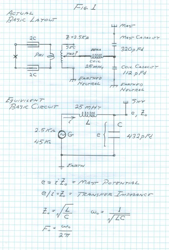
                              Total End Capacity, 432 picoFarad

                              This end capacity is series resonant with a 25 milliHenry inductance coil. This gives rise to a propagation constant, (the resonant frequency) and to a transfer impedance.

                              9) The propagation constant, or frequency, is defined as the inverse of the quantity consisting of the square root of the inductance times the capacitance, this root then multiplied by two Pi. Hence cycles per second.

                              The product,
                              25 milliHenry times 432 picoFarad
                              Results in a frequency of
                              47 Kilo-cycles

                              10) The transfer impedance is given as the square root of the ratio of the inductance to the capacitance.

                              25 milliHenry divided by 432 picoFarad
                              Results in an impedance of
                              7600 Ohm

                              This represents the output impedance of the Tesla Magnifying Transformer.

                              11) The basic circuit is shown in figure 1:


                              In basic terms, a 45 Kc/sec 2500 Ohm source of alternating current energy energizes a large series resonant circuit consisting of an inductance coil and elevated capacity structure. At 45 Kilo-cycles per second, every ampere supplied to the extra coil gives rise to 7.6 Kilovolts at the elevated capacity terminal. The effects of higher harmonics and distributed constants can raise this potential by no more than 50% over the base 7.5 KV. Hereby, for a capacity potential of 1000 KV, the input current to the extra coil must be 132 amperes at 45 Kilocycles per second.

                              12) This derives the total KiloVolt-Ampere reactive activity of the extra coil in 1000 KV operation, hence, the total activity;

                              132 MegaVolt-Ampere

                              This is a substantial activity of 174 thousand horsepower, remembering that this is an average value, the peak value is unknown.

                              13) In conclusion, the Colorado Springs Tesla Magnification Transformer is a very simple system, no more than a giant series resonant circuit with an approximately sinusoidal waveform rendered asymmetrical by a moderate dampening constant. The extra coil is not operating as a transmission network of distributed constants, but only as a basic inductance coil. Hence the length of wire on the coil is somewhat immaterial. The mast capacitance swamps out the extra coil self capacitance, this suppressing transmission modes of higher harmonics.

                              This transformer is seen to be somewhat disappointing to the theorist. No fancy travelling wave interaction nor any stupendous harmonic conjunctions, only a Big Series Resonant Circuit. It can be surmised that the Colorado Springs Transformer was incapable of full mono-polar operation, due to the suppression of distributed constants. What is fortunate is that with the material hereby provided the Colorado Springs Tesla Transformer can be scaled down to any convenient size for experimentation. This setup is now quantified, and the mystics can remain silent.

                              73 DE N6KPH

                              Reference Index (From Colorado Springs Notes)
                              Page 43 & 58 Primary Circuit
                              Page 67 Primary Length
                              Page 203 Primary/Secondary Dimensions
                              Page 206 Secondary Frequency
                              Page 211 Secondary Inductance
                              Page 260 to 267 Capacity Mast
                              Page 318 Extra Coil Dimensions
                              Page 357 Extra Coil Ground Frequency
                              Page 359 Extra Coil Mast Frequency
                              Page 363 Extra Coil Free Frequency
                              SUPPORT ERIC DOLLARD'S WORK AT EPD LABORATORIES, INC.

                              Purchase Eric Dollard's Books & Videos: Eric Dollard Books & Videos
                              Donate by Paypal: Donate to EPD Laboratories

                              Comment


                              • Geometric Algebra's Circuit

                                6SN7 runs best with 300 volts on the plate. 6SN7 will put out a good 5 watts at this voltage. The cathode resistor should be 1000 ohms and for safety 2 watts carbon, ideally. Make sure not to burn the tube out. Put a ma meter on the plate circuit - not on the rf side. And make sure it stays around 20 ma. Your plate voltage looks too low and the cathode resistor is 10k in your circuit just for tuning and setup to ensure not to burn out the tube. Once you feel confident that everything is working ok, then you can go with the 300 volts on the plate and the 1k cathode resistor. Make sure both sections are in parallel.

                                http://www.hifitubes.nl/weblog/wp-co...g-sol-6sn7.pdf
                                Last edited by t-rex; 08-02-2013, 11:15 PM.
                                SUPPORT ERIC DOLLARD'S WORK AT EPD LABORATORIES, INC.

                                Purchase Eric Dollard's Books & Videos: Eric Dollard Books & Videos
                                Donate by Paypal: Donate to EPD Laboratories

                                Comment

                                Working...
                                X