Announcement

Collapse
No announcement yet.

Eric Dollard

Collapse
This is a sticky topic.
X
X
 
  • Filter
  • Time
  • Show
Clear All
new posts

  • @all,

    The larger the magamp, the better. For anybody attempting to replicate this, make sure that you are at least using enough material to be equal to or greater than the amount of steel that I am using for my magamp cores. If the cores are too small, you might have difficulty accurately measuring the power consumption/production.

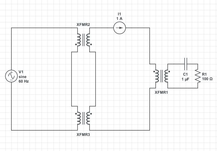
    The magamp cores act like a sponge. When they are externally saturated by the modulation winding, all of the magnetic flux that is originating from the power winding is thrown out into the permeable space surrounding the Constant Current Circuit and the saturation/desaturation cycles manifests as sinusoidal current superimposed on Constant Current which causes the EMF to develop in the output transformer. The larger the magamp core, the more flux lines that can thrown out of the core and turn into output EMF.

    Dave
    Last edited by Web000x; 09-22-2012, 12:41 AM.

    Comment


    • BH Curves

      I did some BH curve tests on my magamp core material. The screenshot on the left is measuring the magnetizing force, H, produced by one of the 184 turn power windings and is measuring the flux density, B, from the control winding.

      The screenshot on the right is measuring the magnetizing force, H, produced by one of the 184 turn power windings and is measuring the flux density at the other 184 turn power winding, this with the control winding shorted out in order to make this possible.

      I did both tests because it is awkward to try an do a BH curve test on a core that is intertwined with another magnetic circuit. I'm sure that between the two test, someone might get the gist of how this material behaves.


      Dave
      Last edited by Web000x; 09-21-2012, 11:19 PM.

      Comment


      • The Movement of Energy During Parametric Variation Pt.1

        I’m glad to see people are still interested in this subject! My hat goes off to Dave for his relentless persistence and is now duly rewarded with the fruits of his labor - a real over-unity electrical power supply. Good work!

        Foreword:

        This rest of this whole post may be redundant, as it contains little “new” content, but I feel the fundamentals of AC power should be addressed for anyone who is going to be building an AC type parametric saturable reactor unit. (Bear in mind that this ISN'T the only way to achieve "energy synthesis" with parametric variation! I've been working on a DC switch-mode unit that has shown great promise) Also, I have a small subtopic pertaining to how I see what’s going on during the whole everything with parametric variation, for those who would like to see an alternate view of what’s going on. *This write-up unexpectedly turned out to be quite long, hopefully someone finds some helpful explanations… and not something that puts you to sleep while reading.

        Movement of Energy in Relation to AC:

        With Alternating Current we can have our enigmatic quantity of source “energy” being:

        *) “Synthesized” through a negative resistance or conductance (CONVERGENCE of energy from the ambient into the circuit seen as a Voltage Rise [excess webers per second] or Current Rise [excess coulombs per second] -- a NEGATIVE ENTROPY (self-ordering) effect)
        1) "Dissipated" through an ohmic resistance (divergence or diffusion of energy from the circuit back into the ambient as infrared radiation)
        2) "Stored & Returned" through a Reactance or Susceptance (circulation of energy in the circuit, essentially trapped "near field" energy)
        3) "Transferred" through a MUTUAL "NEAR-FIELD" coupling, i.e. Transformer or mutual electrostatic fields (transference from one distinct point to another by near-field coupling)

        From the above energy conditions, we arrive at FOUR distinct measurements of AC “Power”:

        1) Apparent Power...(Watt Meter + VAR Meter)..(Complex, Real + Imaginary Axes Value)
        2) Vector Power......(Volt Meter * Amp Meter)..(Absolute, sqrt(Real^2 + Imaginary^2) Axes Value)
        3) Active Power......(Watt Meter)...................(Real Axis Value)
        4) Reactive Power...(VAR Meter)....................(Imaginary Axis Value)

        The Phase angles of the E & I vectors are derived from the above relations; the reactive and susceptive elements of an impedance and admittance have a 90 degree displacement while ALL OTHER components have ZERO phase displacement, i.e. 0 degree displacement between E & I. The resultant waveform seen in an actual circuit is the VECTOR SUM of all the Reactive, Susceptive and Resistive components, where phase=direction and quantity=magnitude. This follows the LAW OF SINES which states that two or more sinusoids added or subtracted together (of the same frequency) result in another sinusoid, of the same frequency, but of a different magnitude, with limits of two equal and opposite sinusoids creating a vector zero or a “cancellation” and thus no wave (*but a “stress” is still present). Multiplication of two sinusoids (E & I), for finding power, results in a DOUBLE frequency product.

        With these relations in mind, the E & I phase angles for ANY circuit condition that looks like an INFINITE TRANSMISSION LINE, i.e. a “resistance” equal to the source impedance, will have NO PHASE DISPLACEMENT and be seen as an INFINITE SINK to a source of energy. A transformer with ZERO leakage reactance (100% coupling) and ZERO winding capacitance acts as a pure "resistance" to the energy source (100% input is transferred to output), thus NO PHASE displacement of E & I exists on the output (if proper resistive load is used) or on the input. *However, an arbitrary phase shift can exist between the input and output waveforms of a transformer.

        This all boils down to the fact that Radiation Resistance (radio antennae, far-field emitter), Ohmic Resistance (conductor losses, infrared radiation), Zero Vector Sum Reactance/Susceptance (100% coupling 0% leakage reactance/susceptance MUTUAL near-field coupling) and an INFINITE Transmission Line ALL look like the same thing to an AC Source, which is a SINK or “point of DIVERGENCE” for energy to be radiated or transferred away from the source supply. NON zero vector sum recactances and suseptances from LC networks, and single L or C networks are seen as a SKINK as well, but in a different form, these store energy and then return that stored energy back to the source at a later time during a falling quadrant of an AC wave. These having a limiting case of ±90 degrees of displacement of either E OR I for single element networks and an ±89 degree limit for both E & I in a LC network (*90 degree for an LC network would yield a ZERO vector sum). *The zero vector sum LC network elements oscillate between each other rather than the source acting as an “open” (Infinite Resistance, parallel connected) or a “short” (infinite conductance - series connected) to the flow of AC power from the source.

        Action of Resistance & Negative Resistance:

        An important question an observant person may ask would be “why do we always try to get electrical circuits to ‘look’ resistive instead of reactive”. The reasoning behind this and the bulk of this post is due to the MOVEMENT of ENERGY and subsequently its RELATIVE quantity known as WORK and the time derivative of work, POWER. “Resistance”, in the most basic sense, is the direct conversion and RELEASE of energy from one form to another without storing electrical energy. Reactance/Susceptance, in the most basic sense, serve to keep the energy bound to the circuit and therefore unable to be RELEASED… UNTILL A RESISTANCE IS SEEN. Reactance / Susceptance “reflect” the energy back and forth between the source and themselves (like an open or shorted transmission line, single L or C network or non-zero vector LC networks) or between themselves only (zero vector LC network). These discreet movements of energy are defined as Work; the amount of energy “used” or “stored” – a relative quantity. A more rigorously definition of Work can be had as the conversion of a discreet quantity of one form of energy to an equal quantity of another form (the supporting pillar of the Law of Conservation of Energy). Therefore, in any circuit, if we want ALL of the energy from the “source supply” (battery, generator or photovoltaic cell) to be used for a specific purpose such as producing light we need a “resistance” to be seen for a conversion of electrical energy to some other form of energy, in this case nanometer electro-magnetic waves. An incandescent light bulb uses an ohmic resistance to produce infrared radiation (HEAT) THAT THEN “triggers” the metal conductor to produce HIGHER wavelengths which are then “seen” as visible light – a very roundabout and inefficient process, but obviously works and is used throughout the world. Radio works the same way, the antennae is seen as a 50 ohm resistive load, which then directs the RF “energy” into space to be received at some distant location. “Well what about an electrical to mechanical conversion”? A resistance is still needed for this conversion, but in this case we see it as a ZERO vector sum of MUTUAL magnetic fields. All forms of energy conversion, that aren’t seen as a cyclic storage and return, utilize a resistance as the “converter”, HOWEVER OBSCURE it may seem.

        The next important question one might ask is “what then is a ‘negative’ resistance”. To resolve this question, a brief study of “positive” resistance seems a good place to start. From the preceding paragraphs we have determined that “resistance”, in an electrical circuit, is a mechanism for the conversion of electrical energy to an equal form of another kind of energy – not just “heat” i.e radio waves, mechanical work, ect. If a “positive” resistance is the DIVERGENCE OF ENERGY AT A POINT, seen as electrical energy released from the circuit as some other form, then a NEGATIVE resistance is the CONVERGENCE OF ENERGY AT A POINT, seen as energy of some form converted into electrical energy. This sounds plausible – more so than “creating” energy. Next let’s examine the purely electrical conditions of a resistance. Ohmic resistance is observed to be a longitudinal voltage gradient across a transmission line, a “resistor” or even a length of conductor, this gradient is the “voltage drop”. We find that the magnitude of current through an ohmic resistance controls the voltage drop. Mathematically, the V_drop [volts] is the product of the ohmic resistance [ohms] and the current through that resistance [amperes], I * r = -V_drop. Since POWER is given as E * I (or V * I) we multiply V_drop by I to get the power delivered to that point, or the joules [work] per second [time] released at that point (as infrared radiation). This mathematically resolves to I^2 * r = -P [watts], resulting in energy continuously diverged out of the circuit at that point.

        From these relations, a negative resistance can be derived as a voltage RISE proportional to the current through the element as I * -r = V_rise and as a SECONDARY energy source proportional to I^2 * -r = P, seen as the CONVERGENCE of outside energy into electrical energy by the negative resistance. Something to note here, is that these equations require a PRIMARY source of electrical energy for the current term I in each equation. These relations are based on the theoretical concept of an OHMIC negative resistance, which as of yet, has not been found. We will conclude that an OHMIC negative resistance is out of reach of the experimenter.

        Continued in Pt.2
        Last edited by garrettm4; 09-22-2012, 05:55 AM.

        Comment


        • The Movement of Energy During Parametric Variation Pt.2

          (Continuing from Pt.1)

          The above problem leads us to find a more exotic negative resistance in the form of the HYSTERESIS of the NEAR-FIELDS (magnetic & electro-static) with the induced MAGNETIZATION/POLARIZATION of a reactive/susceptive storage element. The hysteresis of an electrical storage element, say a capacitor, is experimentally found to be in the DIMENTIONS of an OHMIC RESISTANCE. Which explains why we feel a lossy capacitor get “hot” when we pass a current of 1megacycle through it but not when we pass a current of 60cycles, with both conditions having equal current magnitudes. This form of hysteresis is the natural lagging of the dielectrics polarization alignment to the applied field, a molecular interaction (dipole relaxation time), resulting in the EQUIVALENT of an OHMIC resistance in parallel with the storage element; thereby forcing a discrete quantity of electrical energy to be removed as an equal quantity of energy in the form of infrared radiation or “heat”. This NATURAL hysteresis is of no use to us in our quest for a negative resistance, BUT it shows that the INDUCTION (magnetization/polarization) is NOT COMPLETELY bound to the applied field, the fact that there was a delay in the movements of one and the other proves this. From the observations made so far, an astute person might ask “is it possible to engender a state of ‘artificial’ hysteresis”. THIS is the FUNDAMENTAL question proposed by the “out-of-the-box” thinker Eric P Dollard. Can we cause the magnetization/polarization to lag the applied fields by a specific angle to form a negative resistance in a reactive circuit? Thereby causing a larger return of stored energy than was put in the element by the PRIMARY energy source, which results in the tentative observation of a SECONDARY source of energy. The most fascinating argument of this conjecture is that the energy entering into the circuit IS NOT going DIRECTLY into the conductor, the effect has nothing to do with ohmic effects. Instead the CONVERGING energy is flowing INTO THE NEAR-FIELD (electro-static or magnetic) outside the wire! This results in the return of energy from the storage element being seen as an excess of FIELD energy i.e more coulombs per second [amperes] or more webers per second [volts]. Going back to the “scientific literature”, between 1910 to 1960, one can find an almost endless supply of books and scientific reports given on parametric variation and it’s relation to negative resistance and conductance, making the question seem much more reputable than you would ever want to believe.

          A Proposed Mechanism for the Convergence of External Energy into a Parametric Device:

          Let’s first start off with a brief summary of electro-magnetic theory by Heaviside.

          “In the electromagnetic theory of J.C. Maxwell, there are three distinct properties of any material or immaterial body, when referenced with electric force, and magnetic force, these are electric conductivity, electrostatic permittivity and magnetic permeability. Hence, the body may support conduction current, it may support electric displacement and it may support magnetic induction. These three phenomena may, and in general do, coexists at any one point. Quantitatively considered, they are all vector magnitudes, each having a definite direction, intensity and density, which are calculated and measured per unit area perpendicular to their direction, in terms of chosen units.

          The ability of a medium or body in supporting a conduction current, electric displacement or magnetic induction, varies with the nature of the body or medium, this brings into use three coefficients to describe the body or medium, the electric conductivity γ, the electrostatic permittivity ε, and the magnetic permeability µ. These coefficients are associated to the electric force, and the magnetic force, the electric force being connected with both the conduction current and the electric displacement and the magnetic force connected with magnetic induction. ” Oliver Heaviside

          Taking from Heaviside’s excellent introduction, Permeability and Permittivity are DIRECTLY related to the ability of a material or immaterial body to support magnetic INDUCTION & electrostatic DISPLACEMENT (magnetization/polarization). Without either property there can be NO field lines as there isn’t a medium to support their existence. Further, these properties, for a given applied field intensity, control the maximum DENSITY of field lines permissible in a material (e.g. iron, Teflon, etc.) or an immaterial substance (free-space/vacuum). Here lies the core engineering relation for Synchronous Parametric Variation of an electrical storage element (capacitor or inductor). By artificially and adroitly controlling the permeability or permittivity of a storage element we can intentionally control the effective storage capacity and thereby cause an artificial hysteresis, or lag, in the “size” of the element with relation to an applied electro-magnetic field. When using an alternating current, we force the element into a state of lowest energy capacity, during the charging quadrant, and when we reach the apex of the signal (voltage for a capacitor, current for an inductor) we forcibly increase the size of the element, for the discharge quadrant of the AC wave. Here lies the most important PARADOX of “free energy” - we have forced the storage element to increase in size but at a point in which the source supply CAN NOT give energy to the storage element, BUT experimentally determined, we have a larger quantity of energy returned that couldn't have possibly been from the original source supply!

          Theoretically, this paradoxical phenomena is based around changing the “electro-SPATIAL” properties of an electrical storage element. These electro-spatial parameters, permeability µ & permittivity ε / reluctivity µ^-1 & elastivity ε^-1, have little to no relation to the "space" in which we perceive with sight and touch, this space is entirely fictitious to the senses. However, the invisible field lines of magnetism and electrostatic displacement demand their existence. Of which, is to be a medium through which they form, propagate and interact, on their own or with one another. This can be viewed as an analog of the space required for our physical existence.

          Using these “electro-spatial” parameters with reference to my first explanation, we store a quantity of energy in a small "space" and then expand this "space" (at the apex of the signal) before returning the original quantity of energy. This paradox causes a negative entropic effect to occur by the fact that there is now an imbalance in the distribution of energy in the newly enlarged space (seen in the storage medium). This act forces the ambient medium (physicists would say "the vacuum virtual photon flux") to converge energy into the newly enlarged space to offset the stress created. This leads to the "storage element" being out of thermal equilibrium with its surrounding environment, thus causing a cooling effect to be seen. This is not a heat to electrical energy conversion but merely a side effect of negative entropy - a real phenomenon.

          This concept can be examined a bit further with usage of negative space, or a vacancy of space. When we expanded the original quantity of storage "space" (in the storage medium) to a larger value, we in effect created a "vacancy" or void equal to the new space subtract the original space. This relative quantity is the newly created negative space. This negative region of space has unusual properties when compared to normal conditions. This region is out of equilibrium with its surrounding environment and therefore creates a stress which causes the convergence of external energy into the void region.

          Here lies the sensible explanation of parametric variation, energy is neither destroyed nor created by the phenomenon, but rather it is the "electro-spatial" conditions of the storage medium that cause a negative or positive stress to be seen (to the surrounding environment). Causing the convergence of energy into the medium (from a negative stress) or the divergence of energy out of the medium (from a positive stress) - but not as thermal or heat energy, a more esoteric form of divergence exists here. The concept of "conservation of energy" still holds true, seeing as how ALL “energy” is accounted for, the movement of energy from each source or sink is all that needs to be observed to see this. However, the overall work, the change of a discrete quantity of one form of energy to another, is not in proportion to that seen by the original energy source, this is because we have a secondary source - the ambient medium.

          (end)

          This post was intended to give a basic outline of how to attack the problem from an analytical view, but sadly, not necessarily from an engineering view due to the enormous requirements of such an effort and the endless possible engineering configurations available for construction embodying the basic principle. Analog engineering is effectively more of a personality choice rather than a strict set of rules and options, there are multiple ways to get the same results.

          Garrett M
          Last edited by garrettm4; 09-23-2012, 02:49 PM.

          Comment


          • Dave, based on your comments and reading the web page about building a mag amp from radio shack parts, I was thinking you might be able to build a similar circuit with series transformers as outlined above. I think you were suggesting this in a previous post. Do you think this would work? If so, there'd be no need to wind any coils, you'd just need to make sure you had large enough transformers and that it was biased properly. Some of the component values listed above would most likely need to be adjusted.

            Comment


            • Originally posted by skaght View Post


              Dave, based on your comments and reading the web page about building a mag amp from radio shack parts, I was thinking you might be able to build a similar circuit with series transformers as outlined above. I think you were suggesting this in a previous post. Do you think this would work? If so, there'd be no need to wind any coils, you'd just need to make sure you had large enough transformers and that it was biased properly. Some of the component values listed above would most likely need to be adjusted.
              You need to take the constant current side of either XFMR2 or XFMR3 and reverse the leads. This way no EMF is induced into the constant current circuit from the modulation circuit. If you apply an EMF to the modulation side of the XFMRs, you should have approximately zero volts reading across the two power windings because the EMFs will cancel.

              If you don't get a very large inductance change on the power winding side from from passing current thru the control winding, the transformers might not work. I have measured my inductance change to be from 140 mH to 14 mH.

              Good Luck,

              Dave

              Comment


              • Hey All,

                I hate to be to be the boy who cried wolf AGAIN 
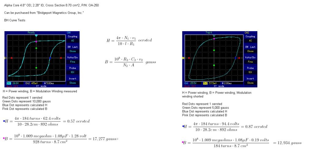
, but I think that I made a flaw in my measurements. For what I thought at the time was a good idea for the sake of simplicity was to measure the modulation winding losses by using i^2*R. i^2*R is for heat losses in the wire and does not reflect hysteresis losses. More investigation shows that there is a proportional energy loss in the hysteresis of the magamp material as there is a 'power gain' in the constant current circuit. I hadn't really taken this into account because the power windings are magnetically opposing the control winding which would cancel out any conventional energy transfer from the modulation winding to the control winding. I normally would have really investigated the circuit before I said anything, especially since the last incident, but this was the circuit that Eric told me to try so I had a bit more confidence in believing what I thought I was seeing. I just wanted to see others try to replicate it to see if the same results would be attained.

                My apologies to all.

                I'll keep trying.

                Dave

                Comment


                • Thermal Losses

                  Dave,

                  "I^2 * r" ISN'T just the "copper" loss it takes into account the hysteresis or "iron" losses AS WELL! Hysteresis is the effective EQUIVALENT of a PARALLEL connected ohmic resistance for ANY storage element be it a capacitor or inductor. Furthermore, ALL thermal losses are seen as an OHMIC resistance. This is why the copper AND the iron of a transformer BOTH heat up independently. Remember E * I = -P, for there to be power "dissipated" voltage and current have to be in phase - this is why all thermal losses APPEAR to be ohmic resistances. Further, the iron loss is composed of multiple factors not solely the hysteresis loss. Hysteresis in modern literature is considered as having two terms, one that is independent of applied frequency (the "static hysteresis loss" - losses do increase with greater frequency BUT the magnitude of the loss per cycle stays the same) and a second term related to frequency ("excess hysteresis loss" - magnitude of loss per cycle increases with increasing frequency), if I get some more free time I will post the expressions showing this. The Eddy Current losses, yet another constituent of the total iron losses, is directly related to frequency and maximum flux density. Other forms of resistive losses are seen as "radio waves" emitted due to RADIATION RESISTANCE which notably has to do with the characteristic impedance of a transmission line and is tightly related to the distance between the send and return wires and the frequency of operation.

                  Remember, you only have two quantities of "power" - what the watt meter says and what the VAR meter says. THESE two readings tell you EVERYTHING about the flow of energy in a circuit. The watt reading is the energy leaving (the source to a sink) the VAR reading is the energy that is circulating (between the source and the load). There need be no confusion, if you examine where the energy is actually going and what it is doing at that point. Also, the COP (coefficient of performance) is a great metric to use when talking about over-unity devices. Take the resistive load energy of the output divided by the effective resistive load seen on the input (in watts) and there's your Active Power COP (watt_out / watt_in). If you want to take into account the TOTAL "effective" energy flow, from input to output, you can find the Vector Power of the output and then divide this by the vector power measured on the input. This metric (VA_out / VA_in) gives you an interesting COP showing the effective flow of energy at the two points. This method of analysis might help in examining whats actually going on with the always mysterious quantity of "energy" we are so desperately trying to get more out than input.

                  To find the EFFECTIVE ohimic resistance (the sum of ALL ohmic losses) in your electrical network, R_eff, just use the AC form of Ohms law on the direct measurements you took from the circuit and use the cos and sin of the phase angle to break out the resistive and reactive terms. If the waveform is distorted then use an oscilloscope to find the peek values and then break down all the harmonics into their designated magnitude and frequency then apply the AC ohms law to each harmonic then combine them with the "sum of the squares" law (Sqrt(R_fundamenal^2 + R_3rd^2 + R_5th^2)) to to find the effective resistance more accurately.

                  *One more thing, a parametric transformer CAN transfer energy from the control winding TO the "POWER" winding - IF this is what you are concerned about with your setup. This mode of operation is how ALL the other people do it in the industry, don't fool yourself into thinking that this is an unused technology - its used ALL the time in telecom and radio. However, they don't APPLY the technology in a way that can operate in over-unity output. The changing of a parameter, say the inductance, at two times the output frequency can allow for a form of ORTHOGONAL mutual near-field coupling. Read "The Parametric Transformer" by E.S. Tez for more on this method of operation - the entire ~700pg thesis is dedicated to conventional 1:>1 output configurations using parametric variation.

                  Hope that helps, and keep up the good work.

                  Garrett M
                  Last edited by garrettm4; 09-22-2012, 10:36 PM.

                  Comment


                  • mix and match??

                    Hi folks – jpolakow suggested I try and digest some of this thread and comment! (I really don’t know what he's got against you guys to invite my inane ramblings )... still I seemed to be naturally blundering into this bailiwick with my musings !
                    I did spend a deal of time reading through the tome that was the "whatever happened to Eric P Dollard" thread which seems to have exited stage left, whatever happened to.... ? Oh never mind ... anyway I could only digest it in little bites due to my inherent stupidity! As for assimilating the information here I'll go make a start! And perhaps see you in a few weeks!
                    In the mean time the logic that brings me here is basically this …. I don’t regard extracting energy from the environment as particularly pertinent to any particular inventor although of course the methods might vary slightly, rather when its being done all be it by John Bedini or Tom Bearden or Eric P Dollard for that matter I consider it extremely likely that a common source is being tapped!
                    Its a miracle that another energy source is available the likelihood of there being many is very remote indeed! Assuming that’s correct I feel free to mix and match any parts of any system that works into another working unit. In very much the same way as I would build an electronic circuit from “Known working blocks”
                    It also stands to reason that folks studying this subject whatever flag they are marching under will be contemplating exactly the same things all be it under different guises and described differently.
                    Consider this circuit of the vibrator PSU described by EPD in that seminal lecture given to the Radio Society.

                    Compare that circuit to the basic construct discussed above and also be so kind as to consider that the circuit that is gradually being built up and described in the following video is an "engineered version" of that happy accident with a “screwy dwell angle”.
                    TV-part III - YouTube
                    Although usually dismissed as “a motor with a capacitor” the Rotoverter has been driven as a high power closed loop system and also demonstrated as a static transformer system! Notice there are distinct similarities between the circuit drawn by Weebooox above and this transverter … Mag-amp … static rotovertor (a rose by any other name)
                    TV-part II - YouTube
                    I think you'll agree that these guys are researching and probing the same area. I often ponder as a COP>1machine has yet to make it out into the public domain on a large scale what sort of percentage of forum members are here with the sole intention of laying false or miss leading spoor, 
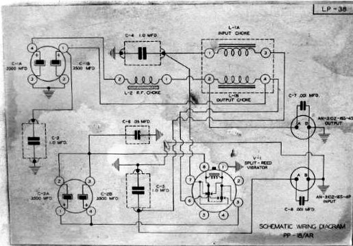
I also find it a bit dubious when another subject seems to be introduced by a stranger to the thread (as Ive just done ) dont you? However it does seem to me that there is a vast ammount of research, written detail, maths, and video which has much in common with the areas of interest you are considering, That being the case I'll post these few links to the PDFs and video's
                    after all some one elses R&D freely given In the same area can save hours and hours of frustrating work and a great deal of money. That being the case I hope you find the time to a least scan the information here ...
                    http://www.byronwine.com/files/plans.pdf
                    http://panacea-bocaf.org/files/Advan...evelopment.pdf
                    TransVerter / Part 1 - YouTube (note there are 60 odd video's in this series)
                    TV-part I - YouTube (only three here)
                    Mean while I'll go and start a steep learning curve on this thread --- see ya soon
                    Regards Duncan
                    P.S as guys like EPD struggle to keep body and soul together and try to put together original trail blazing stuff on a shoe string doesn’t it sorta want to make you puke when you stop to consider the environmental damage being done with projects like this and the pointless expenditure ?
                    World's 10 most expensive energy projects - #9 - GLNG - $30 billion (2) - CNNMoney
                    Yeah scatter a fraction of that cash around some of the brilliance I’ve seen on this forum and watch the feathers fly …. But that’s not on the agenda is it?
                    .

                    .
                    Last edited by Duncan; 09-22-2012, 06:48 PM.
                    Whatever you can do,or dream you can,begin it.Boldness has genius,power and magic in it.Begin it now.

                    Comment


                    • Hi Duncan,

                      Thanks for posting. I watched the Transverter III video but I honestly couldnt see the relation to the PP18. The video seemed to mostly cover the diode plug, which seemed to be a novel way of collecting the output of a transformer into caps, and then switching the charged caps to a secondary circuit. I didnt seem to see any parameter variation there. If you are seeing something I am not, please correct me.

                      I attached a clearer schematic of the one you previously posted, as well as a few hand drawn notes by Eric of a much simplified idea of what is happening in the PP18.

                      The Rotoverter seems interesting, maybe you could perhaps describe in more detail how it properly functions. I have heard it referred to as a rotary version of a Magamp before.

                      Regards,

                      John


                      Please help support my indiegogo campaign: Cosmic Induction Generator

                      Comment


                      • Hi Dave,

                        I suggest you go get a couple of those kill-a-watt meters and put an end to your questions.

                        I'm only interested right now in doing a small scale replication with a single 9V battery powering the whole thing (don't want to spend lots of money on something that isn't proven on a smaller scale).

                        There is no reason this won't work on a small scale which will be a lot cheaper to tweak also. The power can be easily measured if the input & output are properly handled (with a large enough Capacitor to smooth out variations, you can get voltages and currents close to constant).

                        Also, on a small pulse DC core, you can change frequencies & duty cycle easily and I believe keeping the pulsing unidirectional and not AC, core losses can be reduced.

                        Thanks for the update Dave!

                        God Bless

                        Comment


                        • Mag amp

                          You can do essentially what Dave suggested previously with radio shack transformers.


                          I purchased two 2 amp 25 volt center tapped radio shack transformers and wired them up so the voltage across the secondaries cancelled. Then I used rectified ac to a capacitor as a control current. The change in inductance with the control current was huge. Inductance on primary measured .2 H with no control current, and over 20 H with ~.1 amp control current through the secondary. This setup is the real deal for parameter variation.

                          I did get an output voltage through the output transformer, but the power was definitely not impressive with my system. It's an easy setup to play with parameter variation, so I appreciate the post, even if the overunity claim was a mistake. There are oodles of variations that can be done, so the system may still yield interesting results if optimized.
                          Last edited by skaght; 09-23-2012, 03:31 AM.

                          Comment


                          • Garrett,

                            Thanks for your explanation. I really inherently knew all of this, but got caught up in the idea of using lumped constants.

                            My sincerest apologies for getting anybody's hopes up again. I still think this is the way to go, just a different variation.

                            @ Skaght,

                            Make sure you are using DC current in the control winding for your measurements. Sorry if my explanation was short on magamps, just figured that there was a common understanding on this thread.

                            Dave
                            Last edited by Web000x; 09-23-2012, 05:22 AM.

                            Comment


                            • The importance of parametric variation publicised in 1951.

                              Originally posted by garrettm4 View Post
                              (Continuing from Pt.1)

                              Going back to the “scientific literature”, between 1910 to 1960, one can find an almost endless supply of books and scientific reports given on parametric variation and it’s relation to negative resistance and conductance, making the question seem much more reputable than you would ever want to believe.

                              Garrett M
                              Variation of parameters makes it into Hollywood history too. From the original 'The Day The World Stood Still', 1951, searching for a new energy source:

                              BARNHARDT
                              (slowly, thoughtfully)
                              Yes -- that will reproduce the first-
                              order terms. But what about the effect
                              of the other terms?

                              KLAATU
                              Almost negligible... With variation
                              of parameters, this is the answer.

                              BARNHARDT
                              How can you be so sure? Have you
                              tested this theory?

                              KLAATU
                              (with a slight smile)
                              I find it works well enough to get
                              me from one planet to another.

                              Professor Barnhardt (the smartest man in the world) was played by Sam Jaffe, who also held a B.Sc. in Engineering and was dean of mathematics at the Bronx Cultural Institute.

                              Comment


                              • Originally posted by Web000x View Post
                                Garrett,
                                @ Skaght,

                                Make sure you are using DC current in the control winding for your measurements. Sorry if my explanation was short on magamps, just figured that there was a common understanding on this thread.

                                Dave
                                I used the same style control current you previously described, rectified AC to a capacitor. There might be some ripple in my control current, but it is DC not AC.

                                S

                                Comment

                                Working...
                                X