Announcement

Collapse
No announcement yet.

Eric Dollard

Collapse
This is a sticky topic.
X
X
 
  • Filter
  • Time
  • Show
Clear All
new posts

  • #76
    Coil tuning

    Hi dR-Green:
    Thank you for the response. I will eventually do the suggested tests but first I want to find out what is the best wire spacing on the secondary for max frequency response. Second, I will build a new extra coil using #13 AWG in lieu of #25 AWG. The problem with holding the can and the meter is that it do influence the readings, but I have to have short leads from meter to ground and between meter and can in order to minimize their contribution to capacity. I noticed even my body's proximity to the test set up influences the readings, so normally I have to step back after frequency adjustment to see that the meter stays at that maximum. One would need a real laboratory setup to do these tests properly. Who would have thought that Eric's simple CRI sketch would require so much effort to be successful.
    If I use a shortened version of the extra coil, i.e. connect at the 49.5 m point then I do get resonance at 1,186 Kc (pretty close to my target 1,188 Kc) with the condenser rings 64 mm apart. Are you suggesting to tune the secondary coil with a full length extra coil for 1,188 Kc by adjusting the rings' spacing?

    P.S. Comments from Eric or any of the other builders also welcome, except I know currently we lost Eric to the wilderness.

    Comment


    • #77
      Originally posted by Nhopa View Post
      Are you suggesting to tune the secondary coil with a full length extra coil for 1,188 Kc by adjusting the rings' spacing?
      I don't know yet, but that's how I did it with the old extra coil. Without adding terminal capacitance the only way to tune it to 3670 was with the rings. This is because the secondary frequency is brought up, so it's no longer tuned to 3670 as it was without the extra coil. So I tuned it back down with the rings.

      The question in my mind is the balance of secondary to extra coil frequencies. If the secondary is brought up by the extra coil, and the extra coil is brought up by the secondary, then at what point are they both properly tuned to the correct frequency through the rings and terminal capacitance respectively.

      To add to that problem, I've been doing tests in trying to figure this out and found that the extra coil direct connection vs 10pF frequency ratio is not constant as different terminal capacities are used, so the tuning relations between the secondary and extra is not linear. Patterns are starting to form but there are still more tests to do, I've been taking all the relevant measurements I could think of so all kinds of relations and graphs could be derived from it which I hope will reveal some interesting stuff. But as Jake said in the coils compendium thread the primary condenser will also bring the frequency of the secondary down, but for the purposes of these tests the intention is/was when I set out to determine the secondary vs extra frequencies, but having all the data in a spreadsheet has revealed more than that, so it might also be interesting to see how/if/what changes when parts are added in the future. So I have my doubts as to the straightforwardness I was hoping for Just takes an hour or two per test to tune the thing when particular frequencies are being aimed for that's all

      Is there any particular reason for the tap at 49.5 turns on your extra coil?

      [edit] As far as the tests I'm currently doing go, I think it will be most important to see if the results are true universally. If the relations are constant and can be estimated on different scales then we're in business Or at least as far as these particular geometries go. If not then I dunno I'll also be rewinding the secondary with thicker wire after I've tested everything with the existing secondary.
      Last edited by dR-Green; 08-03-2012, 02:12 AM.
      http://www.teslascientific.com/

      "Knowledge is cosmic. It does not evolve or unfold in man. Man unfolds to an awareness of it. He gradually discovers it." - Walter Russell

      "Once men died for Truth, but now Truth dies at the hands of men." - Manly P. Hall

      Comment


      • #78
        Coil tuning

        Hi dR-Green:
        The reason for the tap at 49.5 turns was to have a section of the extra coil the same length as the secondary coil length as per a former forum member, who slightly disagreed with Eric on some points. Although, I am following Eric's instructions to the letter, I figured it cost me nothing to place a tap at that point.
        As you indicate in your response things don't seem to be straight forward by I have a feeling that at the end we will have a simple way to calculate, build and test these coils. I now have another dilemma. As I indicated before I will build a new extra coil using #13 AWG wire. We were told that the coil's height to diameter ratio should be one. The diameter is given as .4 x secondary coil diameter, therefore, the coil height should be also the same. Since I will use #13 AWG and 124 turns, I can only wind the required turns for the given height if the turns just about touch each other. If I figure with the 62% wire diameter spacing then my overall coil length will increase by 10 cm or to about 36 cm, and the height to diameter ratio to approx. 140 %. The question is then: Should I ignore the wire spacing, should I increase the coil diameter so I can still wound the required length on the proper height or keep the calculated diameter and let the height increased by 40 % above the recommended? By the way I will also provide a tap point at the same length as the secondary, just in case.
        Please, Eric and all other active builders make comment(s) if you can.

        Comment


        • #79
          What's the frequency of your existing extra coil? If it has the same relation to F as my 126 turns coil had then it will be no good, its frequency is too low. In which case you won't need to rewind it with 124 turns so the spacing problem doesn't matter.

          If your extra coil has the same relation as mine did then the "tentative" calculations are experimentally updated - Extra coil wire length = λ/4/1.24

          I think you should test the existing extra coil to confirm this before trying anything else otherwise maybe you will end up finding out the same thing through a lot of needless work. If you find the existing extra coil frequency as being too low then there's no point in making a new one that's also too low.

          The tap won't quite be the same as an extra coil of a different wire length. For example the height to width ratio at the tap won't be 1:1, and the extra wire that's "not being used" won't just be sitting there as if invisible

          [edit] Try it like this: First measure the extra coil separately with direct connection and with 10pF or 5pF input and note the peak frequencies.

          That should confirm the wire length issue, but if you want to test further, repeat the test you did with the extra coil + secondary, but this time at 1188 kc and the lower peak, note both the secondary meter reading and the extra coil.

          If the secondary meter reading is higher than the extra coil at 1188 kc then the wire length is no good, so then make your new extra coil with λ/4/1.24

          λ = c/F
          c = 299792458
          F = 1188000
          λ = 252.35055387205387205387205387205

          λ/4/1.24 = 50.877127796785054849570978603237 metres
          Last edited by dR-Green; 08-04-2012, 12:06 AM.
          http://www.teslascientific.com/

          "Knowledge is cosmic. It does not evolve or unfold in man. Man unfolds to an awareness of it. He gradually discovers it." - Walter Russell

          "Once men died for Truth, but now Truth dies at the hands of men." - Manly P. Hall

          Comment


          • #80
            Originally posted by dR-Green View Post
            If the secondary meter reading is higher than the extra coil at 1188 kc then the wire length is no good, so then make your new extra coil with λ/4/1.24

            λ = c/F
            c = 299792458
            F = 1188000
            λ = 252.35055387205387205387205387205

            λ/4/1.24 = 50.877127796785054849570978603237 metres
            And if an oscillator ran at 1188kHz, coupled with a 50.8 metre antenna, the antenna system not earthed in the same way it normally is for electromagnetic tuning and radiation ?

            Comment


            • #81
              Originally posted by GSM View Post
              And if an oscillator ran at 1188kHz, coupled with a 50.8 metre antenna, the antenna system not earthed in the same way it normally is for electromagnetic tuning and radiation ?
              Is that a question?

              The extra coil is to be excited/energised from the secondary so the purpose of this is to find out the relative maximum readings with the existing wire length.
              http://www.teslascientific.com/

              "Knowledge is cosmic. It does not evolve or unfold in man. Man unfolds to an awareness of it. He gradually discovers it." - Walter Russell

              "Once men died for Truth, but now Truth dies at the hands of men." - Manly P. Hall

              Comment


              • #82
                I have some tentative data.

                Voltage and capacitance readings are not accurate and are for general reference only. All measured frequencies should be within around +/- 5 kc tolerance (namely the extra coil direct measurements with bigger terminal capacitance are most difficult to pinpoint) (at the general system frequency of 3670 kc). Percentages are relative to system F therefore the relations are theoretically scalable. This must be verified.


                Last edited by dR-Green; 08-07-2012, 12:28 AM.
                http://www.teslascientific.com/

                "Knowledge is cosmic. It does not evolve or unfold in man. Man unfolds to an awareness of it. He gradually discovers it." - Walter Russell

                "Once men died for Truth, but now Truth dies at the hands of men." - Manly P. Hall

                Comment


                • #83
                  Extra coil testing

                  dR Green:
                  I really appreciate your contribution to my "success?". I have done some more testing on the extra coil and as you suspected the frequencies are too low. Interestingly when I previously published similar results, Eric said the data is fine. Anyway, here are the results:

                  @ 11 pF can at 5 cm from end of extra coil F=892.1 Kc
                  can at 40 cm from end of coil F=949 Kc

                  @ 5 pF can at 5 cm from end of coil F=948.5 Kc
                  can at 40 cm from end of coil F=990.5 Kc

                  So next I will wind 50.88 m for the extra coil for my frequency of 1,188 Kc.
                  I build the frame soon with D/L=1. The 50 turn will give me about 5 mm spacing between turns. I am picking up the #13 AWG wire tomorrow so I will have something soon. I hope from the wilderness Eric will not send a longitudinal wave lightening to strike me down for doing this short version extra coil.

                  Comment


                  • #84
                    Originally posted by Nhopa View Post
                    I hope from the wilderness Eric will not send a longitudinal wave lightening to strike me down for doing this short version extra coil.
                    Hehe, what, the 50.88 metres or the tapped coil? Eric gave me a wire length to use with a reference to 124% velocity factor, so my reverse mathematics came up with λ/4/1.24 as being the logical calculation that gave an answer 3cm out from Eric's given wire length for 124%. That was the only reference point and no one has confirmed or denied it since so I consider that to be correct for now.

                    I think what we are always forgetting is that this is all experimental, the design needs to be updated based on the experimental results. From what I can make out I think the "strictness" was mainly down to the fact that Eric wanted specific data on the known coil designs, but now we have that I think from my extra coil and concatenated mode tests, your secondary, and Geometric Algebra's something that hasn't been published (??), all the necessary data has been acquired (and applied to the Colorado Springs setup). So now I think it's down to the experiment and using the collected data to develop something that works.

                    On a side note in case you haven't seen it I started a coils compendium thread here. The testing is all presented sequentially with Eric's responses etc so the "evolution" is easier to see:

                    http://www.energeticforum.com/renewa...ompendium.html

                    Oh yeah, with the new wire length I suspect the extra coil frame doesn't "have" to be the size from the calculations - I think that's just for convenience of not building a new frame. I think it would be ok to make a smaller frame for more turns, perhaps closer to Tesla's CS extra coil? This should also theoretically give a higher potential I would think, which is basically the whole point of the extra coil. As long as it's still 1:1 height to diameter then the only real difference would be the number of turns and the spacing.

                    [edit] The graphs above are now also updated and compiled into one as I finally figured out how to get Excel to lay it all out properly. What's interesting is that the extra coil direct and secondary cross over when both are tuned to approx 72%, the extra coil 10pF is at 100%. This is also the general area with the highest concatenated mode potential.
                    Last edited by dR-Green; 08-07-2012, 01:55 AM.
                    http://www.teslascientific.com/

                    "Knowledge is cosmic. It does not evolve or unfold in man. Man unfolds to an awareness of it. He gradually discovers it." - Walter Russell

                    "Once men died for Truth, but now Truth dies at the hands of men." - Manly P. Hall

                    Comment


                    • #85
                      Some considerations on the tentative tuning relations data. I believe the Tandem mode relation confirms what Eric said. In this mode the condenser rings and extra coil act as one terminal capacitance on the top of the secondary. Therefore as the extra coil terminal capacitance is increased, condenser rings capacitance decreased, the working frequency of the secondary in tandem mode rises, and as the proportions of terminal capacitance vs rings capacitance is not linear or balanced, at a certain point the tandem frequency is unable to go beyond a certain level and then begins to decrease again, as the "secondary terminal capacitance" consisting of the extra coil continues to increase to keep the concatenated mode frequency constant.

                      Originally posted by T-rex
                      Two modes of resonance exist, the first is the longitudinal, the second is the transverse. For the first the extra coil input is inductive and thus subtracts from the ring capacitance. For the second mode the extra coil is capacitive and adds to the ring capacitance. The potential meter here is measuring the secondary potential. In the second mode the rings and extra coil all are one terminal capacity so the secondary acts with this as a somewhat lumped LC circuit. In the first mode it is a pair of coupled transmission lines so the magnification factor drops because of travelling waves, and additional losses.
                      Originally posted by T-rex
                      Two modes are possible for extra coil in relation with the secondary coil. Both involve quarter wave resonant rise, this the fundamental of resonant transformation. Its also known as constant potential to constant current transformation. A constant potential is a zero impedance (short circuit) a constant current is a zero admittance (open circuit). Departure from these zero values alters the coil distribution to something other than a quarter wave.

                      This quarter wave can exist in a distinct pair of manifestations. The first mode is when the quarter wave is distributed over the length of both extra and secondary windings as a whole, a pair of eighth waves let us say. This is the TANDEM mode. A multiplication in potential is derived hereby since the extra coil exhibits a higher transmission impedance thereby giving rise to a greater EMF between turns and thus a higher termination potential. All photos of my Bolinas and Integratron setups operated in this mode. It is the easy one to achieve.

                      The second mode of the extra coil and secondary coil connection involves two quarter wave distributions, one on each coil. This is not to be considered a half wave however. This mode is the CONCATENATED connection.It compounds the quarter wave resonant rise of the secondary coil with another quarter wave rise in the extra coil, hence a concatenated resonant rise. This is the holy grail of resonant transformer design and unheard of potentials may be gained in this manner. To derive this analytically is extremely difficult, it is an advance transmission line problem. It might not even be possible to calculate or even achieve this mode of resonance, but we are going to give it a try.
                      The "secondary" measurements could therefore effectively be said to be the tandem mode frequency of the secondary minus its extra terminal capacitance. In this case I think it should be possible to get similar "tandem mode" results simply by replacing the extra coil with a large capacitance. This could be something to try at some point.

                      As for the concatenated mode, that seems to be a little more tricky

                      Taking a rounded up/down value of 72% of F as the tuning for the extra coil and secondary

                      If F = 3670 kc
                      Luminal wavelength = 81.68 metres

                      72% tuning = 2642.4 kc
                      Effective wavelength = 113.454 metres

                      Both coils tuned to 72% "total effective" wavelength = 226.909 metres
                      Effective frequency = 1321.2 kc

                      F to effective frequency ratio = 277%

                      Effective frequency to F ratio = 36%

                      This could only be if the coil was operating in 1/2 wave mode.

                      1/2 wave frequency = 1835 kc

                      Effective frequency to 1/2 wave frequency ratio = 72% (= tuning factor of F)

                      Hypothetically, if this was the case then it would be reasonable to think that this is a 1/2 wave situation with the coil operating at 72% the effective luminal frequency due to losses and burdens and what not.

                      However, while at 1/2 wave it would be operating at 72%, at 1/4 wave it would be operating at 100%. So where did the losses and burdens go?

                      This "total effective frequency" of 1321.2 kc is not measured, neither is the 72% tuning factor of 2642.4 kc. So this can't be the case.

                      At 72% tuning, what is measured is:

                      Concatenated frequency = 3670 kc
                      Tandem frequency = 1813 kc

                      3670 kc = 138% effective frequency of 2642.4 kc
                      1813 kc = 68.6% effective frequency of 2642.4 kc

                      This seems to confirm "faster than light" when the extra coil is implemented in concatenated mode, and "slower than light" in tandem mode when the extra coil is just a lump of metal. At least theoretically if the coiled wires were lengthened to 72% tuning rather than through additional capacitance.

                      Bearing in mind that at 72% of F, relative to the wire lengths of the coils:

                      Secondary luminal frequency = 5730.4 kc
                      Extra coil luminal frequency = 4550.8 kc

                      72% F Secondary = 46.11% luminal
                      72% F Extra coil = 58% luminal

                      Also, while tuned to 72% of F the extra coil with 10pF input is measured at 100% F.

                      As I don't believe the coil is operating at 277% as one length of wire, it's not at 72% in 1/2 wave mode, and there is no significance to the 72% frequencies beyond standalone operation, the only other explanation in my mind is that there are two 1/4 wave actions going on. There are two modes of extra coil coupling as explained by Eric which is responsible for this increase in frequency from the 72% tuning factor up to 100% of F. And the tandem mode operation is not a 1/2 wave equivalent as the ratio to F is clearly variable.

                      Last edited by dR-Green; 08-08-2012, 06:54 AM.
                      http://www.teslascientific.com/

                      "Knowledge is cosmic. It does not evolve or unfold in man. Man unfolds to an awareness of it. He gradually discovers it." - Walter Russell

                      "Once men died for Truth, but now Truth dies at the hands of men." - Manly P. Hall

                      Comment


                      • #86
                        Law of Electro-Magnetic Induction, Twelve. (1 of 4)

                        (1) In the last section it was shown that a Synchronous Machine can synthetically produce reactive power. The practical embodiment of this feature is the regulation of long distance power lines. No stored Energy of Magnetic Induction, nor that of Dielectric Induction, is present to account for this reactive power flow.

                        In the chapter “Reaction Machines” Steinmetz continues with a more in depth analysis of parametric E.M.F. production. Here Steinmetz presents a situation where a Synchronous Machine can synthesize its own D.C. excitation. This is with no outside source of current to develop the M.M.F., nor any remnant Magnetism.

                        (2) The chapter “Reaction Machines” gives a more theoretical analysis of Hysteresis. Here the Hysteresis is no longer connected with Saturation, it is independently synthesized by the machine. A pair of Hysteresis Cycles can be formed, one is a forward cycle representing Energy consumption, the other is a reverse cycle representing Energy production; see hysteresis motor.

                        It is assumed thru the Law of Energy Continuity that the rotating shaft transfers the Energy that is produced or consumed in an Electrical form. The E.M.F. developed in the parametric machine however is unlike that developed by the Motor-Generator. The Motor-Generator is a Constant Magnetism machine and the energy transferred is strictly a function of shaft rotation. The regulation here between mechanical and electrical forms is definitely established by the Law of Energy Continuity.

                        The parametric E.M.F. is developed by a variation of Magnetism, it is not constant, but pulsates with respect to time. In this situation the machine operates in the constant Current condition and the Energy transferred is a function of Inductance variation via shaft rotation, but not shaft rotation directly. This complicates the Law of Energy Continuity.

                        (3) In the Synchronous Machine irregularities in pole facings and winding distributions give rise to a pulsation upon the normally constant Magnetism. This constancy is a characteristic of operation as a Motor-Generator. The E.M.F. of rotation and the E.M.F. of variation combines with it to give an effective total E.M.F. at the machine terminals.

                        Steinmetz suggests no apparatus for developing an E.M.F. by parametric means in his A.C. books, however the Alexanderson Alternator was under development at the time of writing of the Fifth Edition, 1916. In general these parametric variations in rotating machinery are hereby considered parasitic phenomena, just as with Saturation and Hysteresis in magnetic material. These effects are to be minimized not optimized. It is however in this series of writings that the optimization of parametric E.M.F. generation is sought, and its application to the Law of Energy Continuity studied.

                        (4) In the next chapter, “Distortion of Waveshape and Its Causes”, Steinmetz further develops the analysis of Synchronous Parameter Variation. The material presented in this chapter is minimal. Dimensional in-congruities, irrational units, ambiguous equations, and typo errors render the understanding of this chapter difficult. Also, again Saturation and Hysteresis become merged into a common phenomena, this blurring the true relations between Amplitude and Phase distortions.

                        In “Distortion of Waveshape and Its Causes” Steinmetz also gives an analysis of the synchronous parameter variation of Resistance, such as in Arc Lighting Systems. Here the remarkable condition exists that a form of reactive power is produced, however with no phase displacement. It is noted by Steinmetz that, where it is Inductance variation gives rise to an effective Resistance of Energy transfer, here the Resistance variation gives rise to an effective Reactance of Energy storage. This reactance is synthetic, no Field of Induction, nor relative mechanical activity, is present to facilitate any reactive power. This synthetic reactance is a result of the particular cause and effect relations in the variant resistance. Again the Law of Energy Continuity is in question. Here the Law of Energy Perpetuity may even be invalidated. This is an important study.

                        (5) The chapter 25 from “Theory and Calculation of Alternating Current Phenomena” Fifth Edition, 1916, is here re-developed in the following, concentrating of a general equation for the synchronous parameter variation of Inductance and the E.M.F. developed thereby. Symbol standardization, and rationalizing by removal of pi and root two, will be applied to the expressions of Steinmetz.

                        The parameter variation in this chapter is of the synchronous type. Here the Inductance of a reactance coil with an applied A.C. current is brought into synchronous variation at a harmonic rate in proportion to that of the applied A.C. current. Two E.M.F.'s are developed, that of the reactance opposing the variation of Current, and that of Inductance variation. The E.M.F. of constant Inductance and Current variation is compounded with the E.M.F. of constant Current and Inductance variation. Steinmetz fails to separated these two E.M.F's. Here exists a modulation process, the Inductance variation modulating the reactance current variation. Complex E.M.F.'s result consisting of multiple frequencies and with distorted waveforms.

                        In chapter 25, expressions are given for the E.M.F. of rotating parameter variation, as in the Synchronous Machine, and the E.M.F. of stationary parameter variation, as in the magnetic material of the static reactance coil. The two are of basically the same mathematical form thus distinction is not a necessity in the development of a General Equation of synchronous parameter variation.

                        Chapter 25, article 234 begins the analysis, “Lack of Uniformity and Pulsations of the Magnetic Field.” This serves as the basis for the derived General Equation. The sine wave of Magnetism is given by,


                        Where,


                        And


                        Here the Time Angle is the independent variable, this is defined by,


                        And


                        Where,

                        F, frequency in cycles/sec,

                        and

                        t, Time variable, seconds.

                        This time angle is a dimensionless position variable on the A.C. cycle of revolution. Substituting the cyclic period,


                        Gives the Time Angle as the ratio of the time along the cycle to the time of a complete cycle, that is,


                        Or in rational form, in radian,


                        Where,

                        SUPPORT ERIC DOLLARD'S WORK AT EPD LABORATORIES, INC.

                        Purchase Eric Dollard's Books & Videos: Eric Dollard Books & Videos
                        Donate by Paypal: Donate to EPD Laboratories

                        Comment


                        • #87
                          Law of Electro-Magnetic Induction, Twelve. (2 of 4)

                          (6) Let the instantaneous value of Magnetism be given by the relation,


                          Where,


                          Substituting the following relation for Magnetic Induction,


                          Into the general expression segregates the two subjects of parameter variation, that of the Current, i, and that of the Inductance, L. The sine wave of current is given by,


                          And the pulsating wave of Inductance is given by,


                          Here in the Inductance the sine wave of variation is offset, and for a modulation depth of one (100%) the sine wave is a pulsating wave in variation with peaks at zero and twice the value of static Inductance. This is expressed as


                          Where


                          Is the sine wave of Inductance variation. For a modulation depth of zero the cosine term vanishes and the constant term of static Inductance, L, remains,


                          Segregating variations the General Equations for Magnetic synchronous parameter variation becomes,


                          (7) For the condition of Saturation and Hysteresis as exists in magnetic materials the process of saturation is the same for positive and negative half cycles, it is symmetrical. The reduction of Inductance due to saturation in the positive half is the same reduction of Inductance due to the saturation in the negative half. Hence the reduction, or modulation, of Inductance is at Twice the frequency of the A.C. cycle of Magnetism, that is, the Inductance pulsates at Double Frequency. In this situation it is,

                          n = 2 , numeric,

                          Where, n, is the harmonic number.
                          SUPPORT ERIC DOLLARD'S WORK AT EPD LABORATORIES, INC.

                          Purchase Eric Dollard's Books & Videos: Eric Dollard Books & Videos
                          Donate by Paypal: Donate to EPD Laboratories

                          Comment


                          • #88
                            Law of Electro-Magnetic Induction, Twelve. (3 of 4)

                            Two factors exist in the characteristics of magnetic material, Hysteresis gives rise to a phase angle, 
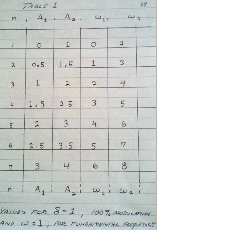
, the angle of hysteresis, and Saturation gives rise to a modulation factor, , the depth of modulation. Hence the sine wave of Inductance variation is expressed by the term,


                            This for Magnetic material.

                            (8) The E.M.F. developed by the instantaneous Magnetic Induction, , is the time rate of its variation,


                            The time rate of variation is expressed as,


                            Steinmetz substitutes the expression for angular rate of variation,


                            Where,


                            And


                            This angular differential is here given symbolically,


                            And it is dimensionless. Here gamma represents an infinitesimal Versor Operator, this of an infinite number of divisions, symbolically,


                            Here the angular frequency, , has become a tensor magnitude, or a Tensor Frequency. The angular rate of variation is thus symbolically expressed by,


                            Substituting into the relation for E.M.F. gives,


                            And differentiating, gives the developed E.M.F. of synchronous parameter variation of Inductance as,

                            SUPPORT ERIC DOLLARD'S WORK AT EPD LABORATORIES, INC.

                            Purchase Eric Dollard's Books & Videos: Eric Dollard Books & Videos
                            Donate by Paypal: Donate to EPD Laboratories

                            Comment


                            • #89
                              Law of Electro-Magnetic Induction, Twelve. (4 of 4)

                              Where it is,


                              A1 being the Lower Sideband Amplitude, and


                              A2 being the Upper Sideband Amplitude. Also,


                              The Lower Sideband Time Angle,


                              The Upper Sideband Time Angle.

                              Note here that


                              Dimensionally establishes the volt.

                              Hence a pair of new Frequencies are generated by the synchronous parameter variation of Inductance, these given by the relations,

                              Lower Sideband Frequency,


                              Upper Sideband Frequency,


                              Where, , is the “Carrier Frequency”, of current variation via the A.C. cycle of the external current source.

                              Hence three alternating electric waves exist in the process of synchronous parameter variation, the values are given in Table 1,


                              Two particular harmonic modulating frequencies are of interest, the second harmonic and the fourth harmonic. For the condition of second harmonic modulation the frequency of the Lower Sideband is equal to the carrier frequency, these two combine in a resultant wave at the carrier frequency. The Upper Sideband is the third harmonic of the carrier frequency and super-imposed upon it creates a regular harmonic waveform. For the condition of fourth harmonic modulation the Lower Sideband gives the Third Harmonic of the carrier wave and the Upper Sideband gives the Fifth Harmonic of the carrier frequency. The odd order series, one, three, five exists here and again super-impose upon each other producing a regular harmonic waveform. All other harmonic modulating frequencies, three, five, etc, give rise to an irregular sequence and thus produce irregular harmonic waveforms. The depth of modulation as well as the Angle of Hysteresis both have a considerable effect on the resulting waveshape. This can give rise to very complex waveforms. It is to be noted that for large depth of modulation, and high orders of modulating harmonics, that the resulting E.M.F. can greatly exceed the E.M.F. of the reactance coil in reaction to the carrier frequency of the external A.C. current source. These processes are worthy of Experimental Research.


                              (9) Steinmetz does not develop this subject much further. The equations for parameter variation in stationary reactance coils, article 236, are dimensionally invalid,


                              A weber is not an ohm-second per radian, it is rightly given as


                              The equations for harmonic summation are not clear and something seems not right. No in depth analysis exists of Resistance parameter variation on a theoretical level, everything is reduced to effective values. E.M.F. is not equated to a co-responding current in many cases making the study of Power Flow difficult in the case of Inductance parameter variation. It is noteworthy in this chapter that Steinmetz gives experimental verification of his parameter variation expressions. It is this feature of Steinmetz's work that makes it of value.

                              (10) Herewith closes this series of writings, “The Law of Electro-Magnetic Induction”. Three principle conditions for the development of electro-motive force have been presented,

                              Constant Magnetism,

                              Constant Current,

                              Constant Inductance.

                              While the condition of Constant Magnetism, the Motor-Generator, and the condition of Constant Inductance, the Reactance Coil, are well known engineering realities, it is the special condition of Constant Current that awaits further analysis and experimentation. In this particular condition of E.M.F. development the Law of Energy Continuity may be in need of re-definition. Here the Law of Energy Perpetuity, the holy dictum of modernistic physics, may possibly be invalidated.

                              73 DE N6KPH SK.....
                              SUPPORT ERIC DOLLARD'S WORK AT EPD LABORATORIES, INC.

                              Purchase Eric Dollard's Books & Videos: Eric Dollard Books & Videos
                              Donate by Paypal: Donate to EPD Laboratories

                              Comment


                              • #90
                                Extra coil testing

                                dR-Green:
                                I did not make a new "strong" extra coil yet, but took off the 124 turns of wire from the existing frame and put on new winding of 63 1/4 turns of #24 AWG wire. I did 5 runs with 5 pF, 10 pF, 20 pF, 30 pF and 50 pF with can positioned at 1.5 cm and 40 cm from the end of coil. No graphs, but here are the numbers:

                                can at 1.5 cm can at 40 cm

                                5 pF 1,721.1 Kc 1,849.5 Kc

                                10 pF 1,676.1 Kc 1,847.8 Kc

                                20 pF 1,637.0 Kc 1,815.0 Kc

                                30 pF 1,593.3 Kc 1,803.5 Kc

                                50 pF 1,524.4 Kc 1,787.3 Kc

                                I noticed during testing that the meter readings had a "bump" at lower frequencies, but it was small, that is the meter reading hardly dropped at those points. I did not make note of them, but if they turn out to be important I can easily go back and take note of them. At this point may be I should continue testing the secondary with this "temporary" extra coil before I make a new one with #13 wire. Comments, suggestions from Eric or any other experimenters?

                                Comment

                                Working...
                                X