Announcement

Collapse
No announcement yet.

Eric Dollard

Collapse
This is a sticky topic.
X
X
 
  • Filter
  • Time
  • Show
Clear All
new posts

  • dR-Green
    replied
    Originally posted by Prio View Post
    There is still the question, what is the engineering goal, what can you expect and achieve with this set up?
    Originally posted by Sputins View Post
    That is a good question.

    In general using a properly constructed “Tesla Coil” or a pair of them, there are a number of different configurations, uses and learning outcomes.

    As per JP’s CIG video he states, one wire power transmission, creating radiant matter, transmitting DC through space, and via the TMT configuration, transmitting / receiving power and signals via earth ground. The CIG configuration is also an attempt to model the universe or certain aspects of it. (I.e. The Electric Universe Theory). Where the Dielectric fields interact and are supposed form galactic like formations within a vacuum.

    There are also other practical uses such as inductive heating, electro-medical, and perhaps other uses that are yet to be discovered. (Experiment and see).

    Well, everyone wants free energy or Energy Synthesis and Eric calls it. – I myself doubt that the CIG or TMT leads to that directly of itself. However if the Tesla coil’s telluric wave (displacement current) can interact with the already present telluric currents of the Earth (powered via the Sun), the Tesla coil may provide some kind of 'tap' into the Earth’s natural telluric currents? - So it’s not free energy as such, it’s tapping into what’s already naturally there. As Tesla said, “Connecting to the wheel work of nature”.

    For example it is known there are Telluric currents in the Earth where their magnitude is beyond comprehension. The Sun is what powers these currents, via lines of force between the Earth and the Sun. In a conventional circuit one would need to break the circuit to insert your device in-line with the circuit current in order for the device to work. - The one wire transmission of power may be an answer towards tapping the Earth’s natural telluric currents?

    If you were to ask what are my specific engineering goals, or what do I want to personally achieve?

    This question as no specific answer, an open ended resonant circuit. Subject to finance and time. - I’m just a backyard experimenter who likes to build stuff, generally based on the principals taught by Nikola Tesla, Eric Dollard and other rebel scientific mad-men! - So who knows where it will all lead to in the end? (Prison most likely)?

    Apart from that, my goal is “The education of these principals, aimed at the next generation”.

    Sputins.
    Regardless of what one may or may not seemingly achieve in their lifetime, anyone who does anything that's based on "truth" contributes to the whole in some way because it continues the work and progresses/unfolds the idea to a point that's further along than where they themselves picked it up, and inevitably at some point in the future someone else will pick it up from there, and so the whole thing evolves according to the law of nature. For example, if nothing else, assuming the internet prevails, there are now high resolution pictures and videos of such things that have never been seen by practically any scientist let alone the general public; there are no videos of Tesla demonstrating his currents passing through his body like someone may read in a book, but demonstrations are now available. If just that inspires someone who would otherwise not be inspired in the future, then the overall goal is achieved.

    Originally posted by Nikola Tesla
    Let the future tell the truth, and evaluate each one according to his work and accomplishments. The present is theirs; the future, for which I have really worked, is mine.
    Philosophy aside, get creative! One engineering goal is to perfect the system, also there may be important scientific implications, otherwise as Sputins said, what applications can you come up with or discover etc.
    Last edited by dR-Green; 06-17-2014, 01:19 AM.

    Leave a comment:


  • mikrovolt
    replied
    The general term "Displacement current" was derived as a mechanical analogy by observation.
    If the Alexanderson waves can show mathematical proof of unique properties of electromagnetism then it is a
    Special case of displacement current. It is desirable that counter space not confused with events that are confined inside a vacuum tube or confined or condensed inside between capacitor plates such as casimir or nuclear physics on surface materials in vacuum which are radioactive. It is the assemblage of fractal aether in open air.
    It does relate to the event between the wires of transmission line seen on The Alexanderson model.

    Ambiguity does exist.
    The present status of Maxwell's displacement current - Abstract - European Journal of Physics - IOPscience

    http://www.antennex.com/shack/Apr07/dc_factfan.pdf

    Displacement Current; Scandals in Electromagnetic Theory

    Floyd Sweet The Fallacy of Displacement Current
    Floyd Sweet: Space Quanta Magnifier / Vacuum Triode Amplifier ~ Collected papers, diagrams, photos & videos hmmm

    Isotopic related to displacement current of confined radiation and opaque metals. Even though LMD can penetrates metal it has not been shown
    to be cancer causing.
    Tom Bearden notes HJ Gray used a phenomenon known as dielectric polarization)
    The Tom Bearden Website
    ET Whittaker refers to this but is not the same.

    Release of electric field by impulse piezo material on nickel-63 on page 30 also not the same. This is more related to betavoltaic using novel method of xrays on a source that is radioactive.
    http://homepages.cae.wisc.edu/~blanchar/res/BlanchardKorea.pdf

    What about cosmic rays ? Is there a modified form in nature and how so ?
    Last edited by mikrovolt; 06-17-2014, 02:25 AM.

    Leave a comment:


  • Sputins
    replied
    Questions

    Originally posted by Prio View Post
    There is still the question, what is the engineering goal, what can you expect and achieve with this set up?
    That is a good question.

    In general using a properly constructed “Tesla Coil” or a pair of them, there are a number of different configurations, uses and learning outcomes.

    As per JP’s CIG video he states, one wire power transmission, creating radiant matter, transmitting DC through space, and via the TMT configuration, transmitting / receiving power and signals via earth ground. The CIG configuration is also an attempt to model the universe or certain aspects of it. (I.e. The Electric Universe Theory). Where the Dielectric fields interact and are supposed form galactic like formations within a vacuum.

    There are also other practical uses such as inductive heating, electro-medical, and perhaps other uses that are yet to be discovered. (Experiment and see).

    Well, everyone wants free energy or Energy Synthesis and Eric calls it. – I myself doubt that the CIG or TMT leads to that directly of itself. However if the Tesla coil’s telluric wave (displacement current) can interact with the already present telluric currents of the Earth (powered via the Sun), the Tesla coil may provide some kind of 'tap' into the Earth’s natural telluric currents? - So it’s not free energy as such, it’s tapping into what’s already naturally there. As Tesla said, “Connecting to the wheel work of nature”.

    For example it is known there are Telluric currents in the Earth where their magnitude is beyond comprehension. The Sun is what powers these currents, via lines of force between the Earth and the Sun. In a conventional circuit one would need to break the circuit to insert your device in-line with the circuit current in order for the device to work. - The one wire transmission of power may be an answer towards tapping the Earth’s natural telluric currents?

    If you were to ask what are my specific engineering goals, or what do I want to personally achieve?

    This question as no specific answer, an open ended resonant circuit. Subject to finance and time. - I’m just a backyard experimenter who likes to build stuff, generally based on the principals taught by Nikola Tesla, Eric Dollard and other rebel scientific mad-men! - So who knows where it will all lead to in the end? (Prison most likely)?

    Apart from that, my goal is “The education of these principals, aimed at the next generation”.

    Sputins.

    Leave a comment:


  • orgonaut314
    replied
    That is also the reason why Eric uses tubes I think. He mentioned that in one of these colleges. The tube forms a capacitor in the direction of the conduction (with high voltage) and that way resembles the analog of the Tesla coil better? Conducting or raising Tesla waves.

    Leave a comment:


  • orgonaut314
    replied
    Originally posted by dR-Green View Post
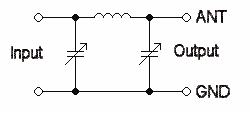
    A Pi network is a capacitor and inductor arrangement that looks like π, or the character Pi. It is an impedance matching network to match a source to a load impedance.

    You can actually make a pi network with two coils and a capacitor. That looks more like Erics analog of the Tesla coil. I am thinking that perhaps that would make the Tesla waves even stronger?

    Leave a comment:


  • orgonaut314
    replied
    Originally posted by T-rex View Post
    New paper by Eric P. Dollard:

    Electromagnetic Induction and Its Propagation – This is a draft paper, which will be formatted better at a later time. The contents of this paper will be a part of the 2014 Energy Science & Technology Conference presentation called The Extraluminal Transmission Systems of Tesla and Alexanderson: Electromagnetic Induction and Its Propagation (pdf)

    New page on ericpdollard.com where a collection of his papers will be available as free downloads: Free Papers | Eric P. Dollard – Official Homepage
    Repeatedly Eric has said that the education system is a ly and I have to agree with him on a factual level.
    A course in electromagnetic starts with the electron and the Drude model to explain everything about currents and fields but than when they get to magnetic induction they have to introduce Faradays law because with the Lorentz forse and electrons you can not explain the situation where a magnetic field gets stronger and induces an EMK. There is nothing moving in that case. When the circuit loop is moving in a not uniform magnetic field you can use the Lorentz forse to explain the EMK but when no loop or coil is moving that Lorentz equation does not work. So they finally mention Faraday who said that a magnetic field is formed to oppose the changing magnetic field. Than they get to the Maxwell equations because Maxwell discovered that an electric field is formed to oppose a changing electric field. And than we get to electromagnetism and the Poynting vector. Fine and than? Nothing. They do not go back to the early circuit theorie and now explain the currents with Maxwell. They just leave you in the middle all confused and than you get your bull.

    This article very clearly points out that the education system has to change. That people should learn the Maxwell approach right away and not be bothered with electrons. It is also a useful way for us to understand Maxwell and you find links to learn more until they rewrite the books.

    http://www.ippp.dur.ac.uk/~davis/Ene...icCircuits.pdf

    Now this ly is almost impossible to get rid of but I ask everyone to look at superconductors. There the surface current is 100nm deep. Do these electrons carry the energy or do they form the obstructors of the electromagnetic energy? The boundary conditions for the field equations not the energy carriers.

    Leave a comment:


  • mikrovolt
    replied
    “Pi network” is a term coined for vacuum tubes, really it is only one type of matching
    Network. The man’s hand gestures an arc gives a rough visual of induction.
    With a poor match the gesture might be flat.

    https://www.youtube.com/watch?v=7bDyA5t1ldU

    DC is less complicated to understand circuit impedance simple resistace.
    A matching network is to form a hand shake between signal output and an input port for
    example between a signal generator and an amplifier. Why because a mismatch would cause reflection that would block the signal also they act as a filter to reduce harmonics.

    I chose this video as a hands on example of impedance matching for tesla coil at 3.47 Mhz. The value of the HV capacitor or double sided copper clad
    can be calculated using online calculator to determine surface area for 3.17
    followed with a 2n5109 would make inexpensive signal source look awesome.

    I built a ten turn coil yesterday like the one in the video. Using a signal generator I derive a value in uH then divide by 10 gives me the actual uH per turn. The matching network when complete can be checked out of circuit bt terminating it with a 50 ohm resistor.

    https://www.youtube.com/watch?v=fUo6IhSouEI

    Leave a comment:


  • dR-Green
    replied
    This is an updated experiment with the slightly higher power amplifier compared to last time, and with the bigger capacitance terminal/tuned extra coil. Last time a 1.5V grain of rice bulb was barely lit, this time it popped within seconds.

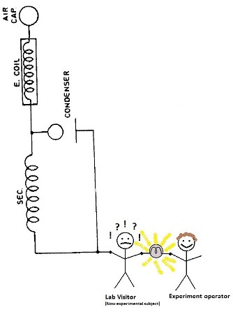
    Basic setup is somewhat similar as shown in Colorado Springs Notes page 360, the difference being that my extra coil is connected to the top of the secondary rather than a ground plate.


    Actual connections


    28V bulb, transmitter not at full power


    28V bulb, all the lab lights off


    Within 3 minutes the 28V bulb had blown


    240V 15W bulb


    240V 15W bulb, all the lab lights off

    Leave a comment:


  • dR-Green
    replied
    Originally posted by Sputins View Post
    Very clever trick there dR-Green, I love it.

    I don’t think we’ve seen that before on the forum!

    I rarely have lab visitors either, but when the next appropriate visitor comes around I must give that one a try! - That is if I can find an enthusiastic experimental subject! Lol, It will probably have to be me or someone else who’s less than enthusiastic!

    A result like that deserves a pictorial response!

    How about using the receiver coil (or CIG) with certain bulbs and experimental subjects in between?

    Credit given
    Thanks! Hehe I like the diagrams, although I think the experimental subject will have question marks floating around his head wherever he stands! It will be even better with your higher power setup. This is the second time I've done it, I usually stand in the middle myself to spare the visitors from plasma burns and what not. We also used 8x 1.5V grain of rice/wheat bulbs in series which looked more impressive/brighter than the big bulb, but my friend was nervous so the moment he started to feel a bit of heat he let go of the thin wires, so that only lasted a few seconds. I doubt he was getting plasma burns after the current had passed through me, that may have been caused by the bulb heating up as normal, but I had not mentioned what kind of effects I usually feel to see if he would comment on anything. But as you know thin wires are not usually the parts you want to hold on to.

    This was the first attempt at the same thing a couple of years ago, using spark gaps back in the day.

    A Bulb In Hand(s) - YouTube

    A receiver works with a bulb and one person in between, so I expect it should work just the same with more people. The only question is the amount of power. Working a speaker on the receiving end is certainly possible.

    It should be very good to see these things with a bit more power used!

    Leave a comment:


  • dR-Green
    replied
    Originally posted by ldrancer View Post
    whats pi-network? is pi network, like 3.17?
    A Pi network is a capacitor and inductor arrangement that looks like π, or the character Pi. It is an impedance matching network to match a source to a load impedance.

    Leave a comment:


  • ldrancer
    replied
    whats pi-network? is pi network, like 3.17?

    Leave a comment:


  • Prio
    replied
    Eric Dollard

    Originally posted by Sputins View Post
    Hi Prio
    Thanks.

    A schematic of what part? There isn’t a single schematic (not as yet). There is a system of schematics, each part takes its required learning. There are no real short-cuts. The people building this stuff have done so out of extensive research, study and hard work. I wasn’t handed a schematic either, I had to learn about all of these things on my own. Although I asked some knowledgeable people certain questions and the answers from them lead me in the right direction.

    So what I can give you is a block diagram of my particular setup as in the video.


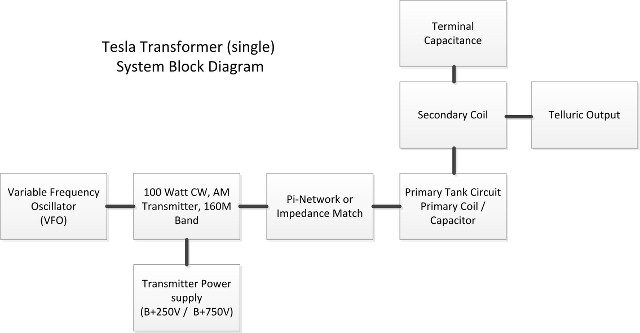
    So if you build yourself a transmitter, either using vacuum tubes (As Eric recommends) or use solid state as dR-Green has done. The transmitter will need a VFO & the transmitter needs its power supply. Then you’ll need a Pi-network or other impedance matching network. Then you have the Primary Tank Circuit, (mine is 3T primary coil with ~900pF capacitor). Next is the Secondary coil. Build it as per Eric’s instructions (mine happens to be in spiral form), use the 20% height to width ratio plans is better. Then you have the terminal capacitance (reflector) and then you have the monopole telluric output. The Extra coil is omitted in this particular diagram. A Radio licence is required unless you can dis-able any air transmission.

    If you use the forum, do your own research & study, have the required building skills, ask the right questions about each of the puzzle pieces, you too could build your own real life Tesla Transformer. Good luck.

    Sputins.
    Thank you very much for the time taken to write this comprehensive answer. Your block diagram is most helpful to get an overview for the Tesla transformer. I try hard to get a comprehensive knowledge of this technology, but when reading trough the forums as an amateur I am not able to judge what is important, less important and useless. So to get an overview when reading through the forums I have to condense all the useable knowledge until I can envision a starting point to build a specific transformer setup. So I have to envision by myself a specific setup, design it and build it. When I have seen your video on youtube, I thought that could be the set up I want to start to replicate.

    There is still the question, what is the engineering goal, what can you expect and achieve with this set up?

    Thank you very much for your time !

    Leave a comment:


  • Sputins
    replied
    Block Diagram

    Originally posted by Prio View Post
    Very impressive ! What kind of powersupply do you use for this setup? Can you post a schematic ?
    Hi Prio
    Thanks.

    A schematic of what part? There isn’t a single schematic (not as yet). There is a system of schematics, each part takes its required learning. There are no real short-cuts. The people building this stuff have done so out of extensive research, study and hard work. I wasn’t handed a schematic either, I had to learn about all of these things on my own. Although I asked some knowledgeable people certain questions and the answers from them lead me in the right direction.

    So what I can give you is a block diagram of my particular setup as in the video.


    So if you build yourself a transmitter, either using vacuum tubes (As Eric recommends) or use solid state as dR-Green has done. The transmitter will need a VFO & the transmitter needs its power supply. Then you’ll need a Pi-network or other impedance matching network. Then you have the Primary Tank Circuit, (mine is 3T primary coil with ~900pF capacitor). Next is the Secondary coil. Build it as per Eric’s instructions (mine happens to be in spiral form), use the 20% height to width ratio plans is better. Then you have the terminal capacitance (reflector) and then you have the monopole telluric output. The Extra coil is omitted in this particular diagram. A Radio licence is required unless you can dis-able any air transmission.

    If you use the forum, do your own research & study, have the required building skills, ask the right questions about each of the puzzle pieces, you too could build your own real life Tesla Transformer. Good luck.

    Sputins.

    Leave a comment:


  • Sputins
    replied
    Cred

    Originally posted by dR-Green View Post
    I rarely have visitors in the lab so I took the opportunity to do a two person experiment earlier. Connections as shown.
    Very clever trick there dR-Green, I love it.

    I don’t think we’ve seen that before on the forum!

    I rarely have lab visitors either, but when the next appropriate visitor comes around I must give that one a try! - That is if I can find an enthusiastic experimental subject! Lol, It will probably have to be me or someone else who’s less than enthusiastic!

    A result like that deserves a pictorial response!


    How about using the receiver coil (or CIG) with certain bulbs and experimental subjects in between?


    Credit given

    Leave a comment:


  • Prio
    replied
    Eric Dollard

    Originally posted by Sputins View Post
    Recorded back in late February 2014. The testing of a single Spiral Tesla coil on CW 160 metres. The Telluric output terminal lighting vintage style, (not an antique) 25 watt filament bulbs (Same setup as previously posted etc.). Video quality isn’t great due to camera compensation and poor lighting / variable light etc.

    Spiral TMT test - YouTube

    I’ve posted this as my first U-tube video, more or less as a test, (a few minute video still took 8 hours upload)?? – Anyway when I’ve worked everything out, I’ll share some of my more recent tests. The sound of your own voice sounds goofy on video!

    Sputins
    Very impressive ! What kind of powersupply do you use for this setup? Can you post a schematic ?

    Leave a comment:

Working...
X