 Tweet
Tweet
Originally posted by Sputins
View Post
-
They're all rip offs of Eric's original design. Most if not all are not using the correct proportions but that doesn't automatically invalidate if they work or not but there is something to the golden ratio proportions.Sincerely,
Aaron Murakami
Books & Videos https://emediapress.com
Conference http://energyscienceconference.com
RPX & MWO http://vril.io -
SPECIAL COSMIC INDUCTION GENERATOR PROJECT ENGINEERED BY ERIC DOLLARD - NEW VIDEO
Check out this project that I've been working on with Eric Dollard non-stop for the last few weeks. https://emediapress.com/2020/09/09/cosmic-induction-generator-2020/
Sincerely,
Aaron Murakami
Books & Videos https://emediapress.com
Conference http://energyscienceconference.com
RPX & MWO http://vril.ioComment
-
Pics are posted at the previous post thru the link above.
 Sincerely,
Aaron Murakami
Books & Videos https://emediapress.com
Conference http://energyscienceconference.com
RPX & MWO http://vril.ioComment
-
Hi,
I have added a new post to my website on:
Cylindrical Coil Input Impedance – TC and TMT Z11
http://www.am-innovations.com/cylind...tc-and-tmt-z11
In the first part of this post I take a detailed look at the small signal ac input impedance Z11 for a cylindrical Tesla coil and TMT system, looking at the series and parallel resonance modes that are characteristic to this type of system. In the second part I go on to use the measured Z11 to take a detailed look at the matching requirements for different types of generators to the cylindrical coil system, and the advantages and limitations of these generators when applied to the exploration of the properties and phenomena of electricity.
The post includes two video experiments covering:
1. The small signal ac input impedance Z11 of a series-fed cylindrical secondary coil with no coupled primary coil.
2. Z11 for a parallel-fed cylindrical primary coil with a parallel vacuum variable tuning capacitor, and no coupled secondary coil.
3. Z11 for a cylindrical Tesla coil primary fed with a bottom-end connected single wire extension on the secondary coil.
4. Z11 when changing the distance between the primary and secondary coils, and hence the coupling between the two coils.
5. Balanced impedance tuning for the upper and lower parallel point frequencies of a cylindrical Tesla coil.
6. Z11 for a Complete TMT system in the near-field to close mid-field region, with a cylindrical transmitter coil and receiver coil, and bottom-end connected with a low impedance single wire transmission medium.
7. Optimum balanced tuning for the cavity of a TMT through adjustment of transmitter and receiver primary capacitor, and transmitter and receiver coupling.
8. Optimum tuning of the TMT system with an incandescent lamp load on the output of the cylindrical receiver coil primary.
Best wishes,
AdrianComment
-
How is this done in coils? I am generally familiar with the use of graduation in e.g microwave antenna theory to provide smooth impedance transition from the 50-ohm line to 377-ohm free space impedance, but the coil-wire-ground-wire-coil system does not seem to admit of much opportunity to provide gradual impedance transitions between the components.Originally posted by aminnovations View Post
That is very interesting. I do not recall seeing any discussion of the third harmonic in relation to the extra coil in the literature, so it is possible you are the first to publish on this point.As the designed harmonic goes up the inter-action between the two reduces dramatically, however also the energy that can be coupled to that harmonic also goes down rapidly. The third harmonic appears to be the best balance between minimising the frequency shift of the secondary, whilst maximising the energy coupled from the secondary coil to the extra.
I am looking forward to your further publications on this topic. In particular since our earlier discussions concerned the necessity of disruptive excitation in producing this class of phenomena, but you appear to have observed it with what I assume is continuous wave excitation.You mean -10dBm, yes? That is quite a good result.
No, I mean 10dBm, although this is only from a single experimental test. I have still have a lot of measurements, experiments, and tests to do before drawing conclusions, and writing-up and reporting on Telluric transference of electric power.
Temporal and spatial coherence being a property associated with sine waves, you are saying this phenomena disappears when the coil is excited with a disruptive discharge? Or is it that the coil's transformation of the disruptive discharge into a sine-shaped waveform which is a precondition to the observed phenomena?The longitudinal in this case is spatially coherent because both induction fields act in the same direction as propagation. The undifferentiated dielectric and magnetic fields of induction act and are as one together in displacement, which is a fully coherent state both temporally and spatially.
Additionally, I am somewhat confused by your characterisation of the dielectric and magnetic fields "acting ... in displacement" since it was my understanding that displacement is a dielectric phenomena.
Ah, I see. Thank you for taking the time to reply!The lower resonant frequency fL and upper resonant frequency fu do not originate from the same resonant circuit, so they are not harmonics of the same resonator. In this case fL (the lower parallel mode) results from the secondary coil, whereas fu (the upper parallel mode) results from the primary.
Comment
-
A colleague was able to perform some rudimentary measurements of a Dollard-style golden ratio antenna using a vector network analyser, similar to but no doubt of lower quality than Adrian's instruments. It was observed that the antenna produced two sets of golden ratio harmonics such thatOriginally posted by Aaron View Post
f_a1, f_a2, ... f_an = N * phi
while
f_b1, f_b2, ... f_bn = M * phi
If there is interest I will try to obtain the full results.Comment
-
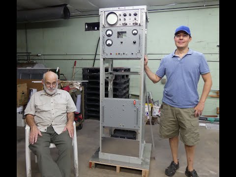
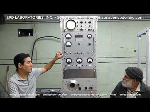
AUDIO MODULATOR for our universal Tesla system is about 90% complete. More details in a video coming soon. In simple terms, this rack is a high voltage audio amplifier...highly specialized one built Navy spec. Building something like this mostly from scratch is quite challenging! Donald Sewell, your dads two Air Force racks are getting put to good use!! Only the HP scope and signal generator were off the shelf.
If your a fan of audio/music, this is going to blow your mind when complete. That is only one of many demonstrations we'll do with this.
Kurt Kung, we have some water experiments in mind with this...will be in touch.
This will also demonstrate some of the creative forces in nature...for Eric Dollard, the name Cosmic Induction Generator was inspired by Wilhelm Reich's book Cosmic Superimposition. Check out Dr. James DeMeo newest presentations on the orgone and the ether. He is the leading authority on the work of Wilhelm Reich... presentations are at http://emediapress.com
We'll be able to do all kinds of higher power longitudinal wave demonstrations, which indisputably flushes many of the foundations of modern day physics down the drain just like we demonstrated last year with the 20:1 scale model replica of Tesla's Colorado Springs Magnifying Transmitter.
It takes a team...Jeff Moe on the right with all the machining help, Jari Karvonen on the left with his 140 miles per day trip to pick up Eric Dollard to bring him to our shop and take him back every day. Troy Kesti is not pictured....he works here on the MWO assembly, but he helped with a few odd jobs on this project. Eric Dollard the modern day Tesla wizard and all his genius engineering and I spent countless hours at the bench fabricating parts, wiring, etc.
Fortunately, I'm in a position to fund all of this out of my pocket, which has been a small fortune, so for the record $0.00 came from EPD LABORATORY, INC 501C3 donations since this is my personal project. All those donations go to supporting Eric's work at the lab in Nevada. Second video walkthru on this will be posted soon. Http://emediapress.com
P1220074.JPGLast edited by Aaron; 09-20-2020, 09:17 PM.Sincerely,
Aaron Murakami
Books & Videos https://emediapress.com
Conference http://energyscienceconference.com
RPX & MWO http://vril.ioComment
-
Hi Marcus,
For the ground system a better low impedance match can be achieved by using a tuned circuit, although of course this is selective with frequency and has to be re-tuned if the operation frequency is changed. This is the same principle as some artificial RF grounds used in amateur radio, where the reactance is tuned out leaving only the series resistance of the wire used as the ground connection. Rather tricky to setup, but improves the low-end connection.Originally posted by Marcus Neuhof View Post
I am planning to do a major study on transference of electric power in the mid and far-field region, including Telluric, over the coming winter and into early spring next year. I have a new substantial ground system in place, and the impedance of this system is lower in the winter months when the ground is heavy with water, and the water-table is much higher. I will be working with linear sinusoidal and impulse excitation and comparing the results and measurements. I will shortly be posting a new experimental article on the website on High-Efficiency Transference of Electric Power which looks at power transfer efficiency using a linear amplifier in the close mid-field region, and this is really the starting point for a more detailed investigation with the transmitter and receiver positioned at increasing distance from one another.I am looking forward to your further publications on this topic. In particular since our earlier discussions concerned the necessity of disruptive excitation in producing this class of phenomena, but you appear to have observed it with what I assume is continuous wave excitation.
What you are calling “disruptive” here is really a highly non-linear impetus, or impulse applied to the system. The point of this impulse is to establish a tension in the system which cannot be balanced or brought into equilibrium through the process of transference. Under these conditions the underlying process of displacement must act in the system, as natural processes always appear to strive for a state of dynamic balance. If displacement did not act under these conditions then we would arrive at a life-destructive condition, that if allowed to continue would simply tear apart the underlying fabric of the system. Instead displacement re-balances the system by advancing, (or accelerating if you like), the dielectric and magnetic field of induction to the correct relationship and proportion for equilibrium.Temporal and spatial coherence being a property associated with sine waves, you are saying this phenomena disappears when the coil is excited with a disruptive discharge? Or is it that the coil's transformation of the disruptive discharge into a sine-shaped waveform which is a precondition to the observed phenomena?
Additionally, I am somewhat confused by your characterisation of the dielectric and magnetic fields "acting ... in displacement" since it was my understanding that displacement is a dielectric phenomena.
Displacement as an underlying process can do this because of the undifferentiated (unseparated), nature of the fields of induction which inherently are spatially and temporally coherent. In contrast the disruptive discharge is in itself a state of transference with many phase relationships between many frequency components, but is also a non-linear one that applies considerable tension to the system. Displacement is a process that underpins transference, and is inclusive, coherent, and involves the undifferentiated dielectric and magnetic fields of induction, whereas transference deals with the differentiated induction fields. When displacement is called forth into a non-linear system certain phenomena are generated including radiant energy, which I treat as an emission from a displacement event. The displacement I am referring to here is not simply a dielectric phenomenon, (which on its own belongs to transference), but rather a totally coherent relationship between the undifferentiated fields of induction, both spatially and temporally.
Best wishes,
Adrian
Comment
-
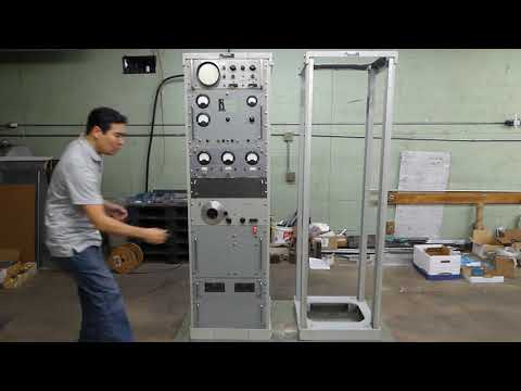
NEW FREE VIDEO WALK THROUGH OF THE COSMIC INDUCTION GENERATOR - PART 2 AVAILABLE NOW
We already sent you a link to the video about the Cosmic Induction Generator that we're working on, which is more like a Universal Tesla experimentation system because it is very versatile and can do a lot of different things. That was explained in the first walk through video.
In this new video, we show you how far we've come in a relatively short period of time - on this website, there is both Part 1 and Part 2 videos and if you didn't watch the first one yet, I'd recommend watching both in order or you will miss out on a lot of information. You'll see in both videos that Eric is truly a genius engineer who cooked this all out of his head based on what I told him I wanted and it all came together perfectly. We're 90% done with the first rack but take a look: https://emediapress.com/2020/09/09/c...enerator-2020/
 Sincerely,
Aaron Murakami
Books & Videos https://emediapress.com
Conference http://energyscienceconference.com
RPX & MWO http://vril.ioComment
-
NEW TELEPORTATION VIDEO - ONLY FOR THOSE WITH A SENSE OF HUMOR
With all the insanity that has spread across this nation, a good laugh is in order. https://emediapress.com/2020/09/22/t...demonstration/
 Sincerely,
Aaron Murakami
Books & Videos https://emediapress.com
Conference http://energyscienceconference.com
RPX & MWO http://vril.ioComment
-
I have a few questions about the Cosmic Induction Generator and the Colorado Springs Transmission System, more so the CIG.
What form of Coax would I have to use for the conductor (which would be the outer coating) on the secondary of the system?
I intend to make a CIG of my own in the near future, when I don't know, but I plan to.
The diagrams I bought designed to operate at 432 kilocycles, the reason for that was I figured maybe I'd try a pythagorean number and see what happens.
The next couple questions are about the Transmission System.
1. Could it be possible to actually adapt modern digital age technology, computers and possibly internet to this?
2. I'm trying to explain this to some friends to increase your audience and I wanted to know, if you were in a shuttle and wanted to communicate with a station on Earth or a space station, would it be possible with this tech?
I wanted to be sure about these 2 questions before I shot off my mouth like an idiot.Last edited by WesTheSavage; 11-08-2020, 01:31 AM.Comment
-
Hi,
I have added a new post to my website on:
High-Efficiency Transference of Electric Power
http://www.am-innovations.com/high-e...electric-power
In this post we take a preliminary experimental look at the transference of electric power using a cylindrical coil TC and TMT, energised using a linear amplifier generator, and also the high power transfer efficiency that can be achieved in a properly matched system. The setup, tuning, and matching of the linear amplifier is covered in detail in the video experiment where a 500W incandescent lamp can be fully illuminated at power transfer efficiencies over 99% in the close mid-field region. The power is shown to be transferred to the receiver through a single wire between the transmitter and receiver coil through the longitudinal magneto-dielectric mode, and not through transverse electromagnetic radiation or through direct transformer induction. This high-efficiency, very low-loss transference of electric power is possible as the dielectric and magnetic fields of induction are contained around the single wire. It is also demonstrated that more than 500W of power can be transferred through a single wire no thicker than a human hair, a 40AWG (0.08mm or 80 microns).
The video experiment demonstrates and includes the following:
1. Linear amplifier generator setup, matching, tuning, and operation to drive a cylindrical TC and TMT system.
2. Measurement and confirmation of the series and parallel modes of resonance for a balanced TC, against the Z11 impedance results, using the generator exciter and an oscilloscope.
3. Transference of electric power from the generator exciter unit, to a single wire transmission medium incandescent lamp load up to 120W.
4. Transference of electric power from the linear amplifier generator to a 500W incandescent lamp load at the TMT receiver output, and subsequently to two parallel 500W lamp loads.
5. Longitudinal magneto-dielectric (LMD) mode measurement through central null with a fluorescent lamp, and mode interference patterns with an ultraviolet lamp.
6. Transference of electric power efficiency measurements up to 99% using an AWG12 single wire between the TX and RX coils.
7. Efficiency measurements up to 100% using an AWG40, 80 micron (0.08mm), 60cm long, single wire between the TX and RX coils.
Best wishes,
Adrian
Comment
-
Hello Aaron, Eric, Adrian, Ernst
Excellent work with the Linear Amplifier from the 2nd Video and have one question for you.
The EHT supply pcb is being driven from what source - 110vAC 60 hz?
The reason I question this is because what is being used in ceramics will not give you the voltage you expect.
My Resonant Negative Ion Generator (RNIG) was built using ceramics from AC 240v 50 hz and only gave about 950 volts when it should have been 5 Kv.
Those in the music game are using this same type of arrangement to power their EHT panel speakers but they do not realise that they are not receiving the voltage they expect due to a too low cycle hz,
The only solution to this problem is to go to an electrolytic which is really only a much higher value but adds the capacity component required and gives the result you are building for - I used 4.7uF 400v.
Individuals enter the high voltage scene but fail to prove their endeavours with a suitable EHT probe meter.
I mentioned this problem here some years ago.
Glad you were able to use the work of Ernst Willem van den Bergh in his excellent presentation in his 'Tesla's Magnifying Transmitter' Book.
One thing here for Ernst is what I suggested to Adrian in the use of the Plasma gap which Ernst presents as stage 4 of the TMT where it is a PLASMA Gap and not a spark gap and how is he adjusting his plasma balls to tune for the correct gap?
An analogue meter is best used here to show current as in any transmitter, tuning for minumum current and maximum output.
Also what frequency is Ernst using and is it the resonant Earth frequency?
See my entry Page 186 entry #2779 onwards.
We have a picture of the overall interior of his Tesla Coil but don't get to see the magic side.
What is most evident from the initial observations of Tesla was that he was most interested in building a rainmaker of sorts but his ongoing experiments showed that he had a much greater and wider use potential in the TMT than just to be a rainmaker.
The Crystal Set Initiative (CSI - TMT) is now being rebuilt and utilising the 4th and 5th stages and my guess is that this is exactly what Eric is now building at Lone Pine - am I correct?
How could I possibly be wrong as I still see him in a very old picture at RCA Bollinas over the top of a TMT like experiment.
EP Dollard RCA Bollinas.jpg
Eric may remember me eliminating his ground line in one of his drawings as not being required but no comment was received as to question why.
This was revealing what Ernst had also discovered in what Wardenclyffe was all about as a direct advancement on the Colorado Springs experiments.
Eric's thyratron TMT Pulser will be used for this rebuild as it is a pulse that is required to provide the trigger action to make rain and that is what I am building for and anything else that may accompany this initiative will be most welcome.
His 2C22 Regenerative Magnifying Receiver (RMR) will also be used as the monitor.
I now have a Spectrum Analyser on the way which is said to be made in the USA but the English used is more Asian than American:
https://www.ebay.com.au/itm/EMF-Mete...F/254651509614
In all of this the only persons of the past that I can see had some sort of a handle on what Tesla was really all about apart from Eric was Edwin Gray and his 'Spark' Tube and William Lyne's 'Free Energy Surprise' - the use of a Plasma.
This was all demonstarted to me by my accidental discovery of what I called 'Impulse Discharge' and what Chernetsky called 'Self Generating Discharge'.
Impulse Discharge at work.jpg
Smokey
Last edited by David G Dawson; 12-13-2020, 01:24 AM.Comment
-
Hello - anybody home?
Eric Dollard Forum:
I go to this Forum today and see that I have some 20 odd private questions from individuals about various segments of my research dating back to 2013 that I have posted here but how come I am only seeing those now and not when they were first posted?
My humble apologies to those people as I was not aware of those messages until today.
I am open to objective criticism but if somebody asks me an intelligent question, I do my best to give a truthful answer supported by the research and to do otherwise is not me.
Those questions would have been better to be presented at the main Forum and not privately and would appreciate those who are still interested to repeat their question - Thanks.
Some of the questions were to do with rainmaking but you must all remember that this is exactly what Tesla first endeavored to design but his early results led to a much greater discovery in the 'radiant energy' and its enhanced properties.
I am also active at Groups io and MeWe and may be more suitable and comfortable there for you and you are most welcome to come and join this specialized arena:
smokey9s@groups.io
notifications@mewe.com
We used to receive notifications when somebody posted here but that is no longer happening and why nobody responds.
Energy Synthesis Montage2.jpg
.
SmokeyComment
-
It looks like you have to log in to the forum and check this thread every time someone replies, else you will not get any notifications after the first one.Originally posted by David G Dawson View Post
I personally wish there was a way to get notifications of all replies to the thread, regardless of whether I had checked it. Aaron, maybe there is something you can do?Comment
Comment